
Related Manuals for Vibe Interactive Collaboration Board


Summary of Contents for Vibe Interactive Collaboration Board
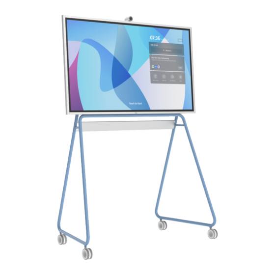
- Page 1 User Manual Vibe interactive collaboration board (Please Read this manual before operation)
- Page 3 Remove any object that could fall into ventilation holes or prevent proper cooling of the display’s electronics. • Do not block the ventilation holes on the body of Vibe. • When positioning the display, make sure the power plug and outlet are easily accessible.
- Page 4 Service: • The casing cover should be opened only by qualified service personnel. • If there is any need for repair or integration, please contact your local service center. If your display does not operate normally, having followed the instructions in this document, please contact a technician or your local service center.
- Page 5 Federal Communications Commission (FCC) Notice (U.S. Only) This equipment has been tested and found to comply with the limits for a Class A digital device, pursuant to part 15 of the FCC Rules. These limits are designed to provide reasonable protection against harmful interference when the equipment is operated in a commercial environment.
-
Page 6: Table Of Contents
2.1. Vibe Assembly notes ..........................2 2.2. Installing the Stand ...........................3 Parts and Functions ......................... 7 3.1. Input/Output ...............................7 Touch Control .......................... 8 4.1. Draw&Erase with Vibe stylus ......................8 4.2. Canvas Operation by fingertips .......................8 4.3. Other Operations ............................8 Pixel Defect Policy........................9 5.1. Pixels and Subpixels ..........................9 5.2. -
Page 7: Unpacking And Installation
The user interface is subject to change, Please refer to the actual machine for user interactions. Unpacking and Installation 1.1. Unpacking • This product is packed with the standard accessories. • Any other optional accessories will be packed separately. • Due to the size and weight of this display, it is recommended for two people to move it. -
Page 8: Stand Installation (Optional)
2.1. Vibe Assembly notes 1. Caution: The Vibe board, and stand are heavy and require a minimum of two people to install. Use caution when lifting them. 2. If screws are found missing or loose, please contact professional repair services or contact Vibe customer service. -
Page 9: Installing The Stand
2.2. Installing the Stand Step 1 1. Open the stand package. 2. Spread the protective sheet in the package on the flat ground and put on the stand.. 3. Install the three parts in the middle. 4. Install the stand on the other side refer to graphic order. - Page 10 Step 2 1. Make the stand standing. 2. Ensure the direction and position of logo are consistent with figure above. Rotate the tube to expose Note: Ensure to hold the both sides to prevent apart. the screw holes then install the screws and plastic caps. 3.
- Page 11 Step 3 1. Remove the rubber plug from the back cover. 2. Insert the side hole of the display into the stand positioning column. Note: User can refer to the triangle symbol on the back cover for the position of the hole. 3.
- Page 12 Step 4 Connect the camera. Note: The camera needs to be inserted into the slot.
-
Page 13: Parts And Functions
Parts and Functions 3.1. Input/Output USB 3.0 USB 2.0 5V/0.9A 5V/0.5A ETHERNET 1 MAIN POWER SWITCH Switch the main power on/off. 2 AC IN AC power input from the wall outlet. 3 HDMI OUT HDMI video/audio output. 4 HDMI IN HDMI video/audio intput. -
Page 14: Touch Control
Touch Control Vibe is equipped with an infrared touch display and can be operated by fingetips or Vibe stylus. The following descriptions illustrate typical operations. More Vibe software manuals and guides can be found at htts://vibe.us/guide. 4.1. Draw&Erase with Vibe stylus... -
Page 15: Pixel Defect Policy
Pixel Defect Policy We strive to deliver the highest quality products and use some of the industry’s most advanced manufacturing processes whilst practicing stringent quality control. However, pixel or sub-pixel defects on the PDP / TFT panels used in Plasma- & LCD- displays are sometimes unavoidable. No manufacturer can guarantee that all panels will be free from pixel defects, but guarantees that any Plasma- &... -
Page 16: Pixel Defect Tolerances
5.5. Pixel Defect Tolerances In order to qualify for repair due to pixel defects during the warranty period, a PDP / TFT panel in a Plasma / LCD- display must have pixel or sub-pixel defects exceeding the tolerances listed in the following table. BRIGHT DOT EFFECT ACCEPTABLE LEVEL 1 lit sub pixel... -
Page 17: Cleaning And Troubleshooting
Cleaning and Troubleshooting 6.1. Cleaning Caution When Using the Display • Do not bring your hands, face or objects close to the ventilation holes of the display. The top of the display is usually very hot due to the high temperature of exhaust air being released through the ventilation holes. Burns or personal injuries may occur if any body parts are brought too close. -
Page 18: Technical Specifications
Technical Specifications Picture and Display Specifications Diagonal screen size 55 inch Optimum resolution 3840 (H) x 2160 (V) @ 60 Hz Optimum frame rate 60 Hz Brightness (typical) 300 cd/m² Contrast ratio (typical) 1200 : 1 Pixel pitch 0.315 mm x 0.315mm Aspect ratio 16 : 9 Color depth... - Page 20 Vibe Inc info@vibe.us +1 (864) 335-2007 https://vibe.us 10400 NE 4th Street, STE 500 Bellevue, WA 98004 Vibe interactive collaboration board Q41G55M111101A Designed by Vibe Inc in Seattle US Made in China...
Need help?
Do you have a question about the Interactive Collaboration Board and is the answer not in the manual?
Questions and answers