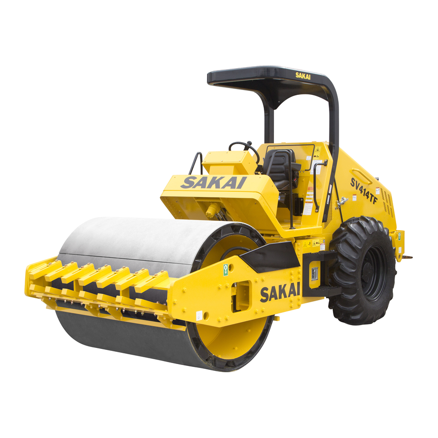
Sakai SV204 Series Operating & Maintenance Instructions

Sakai SV204 Series Operating & Maintenance Instructions

Vibrating roller
Table of Contents

Advertisement

Quick Links

M
M
O
D
E
L
S
V
2
0
4
S
e
r
i
OPERATING
OPERATING
e
s
MAINTENANCE
MAINTENANCE
INSTRUCTIONS
INSTRUCTIONS
Read this handbook thoroughly and understand the whole information
contained before trying to operate, inspect and service your machine!
&
&
VIBRATING
VIBRATING
ROLLER
ROLLER
From SV204D
From SV204D
SV204T
SV204T
SV204TB → 1SV65 - 30101
SV204TF → 1SV65 - 30101
No.
No.
3498-36540-0
3498-36540-0
Series
Series
→ 1SV65 - 30101
→ 1SV65 - 30101
→ 1SV65 - 30101
→ 1SV65 - 30101

Advertisement

Table of Contents
loading

Summary of Contents for Sakai SV204 Series

  • Page 1 3498-36540-0 3498-36540-0 Read this handbook thoroughly and understand the whole information Read this handbook thoroughly and understand the whole information contained before trying to operate, inspect and service your machine! contained before trying to operate, inspect and service your machine! OPERATING &...
  • Page 3 PREFACE PREFACE This operator’s manual serves as a guide for the use of your SAKAI SV204 Series Vibrating Roller for those who are new to the machine, and also for the people who have experience in using the Machine and want to refresh their knowledge for the machine.
  • Page 4: Table Of Contents

    CONTENTS CONTENTS PREFACE MACHINE AND ENGINE IDENTIFICATION NUMBERS ......... 1 SAFETY NOTICES ................... 2 1 BASIC PRECAUTIONS FOR SAFETY ............4 1.1 General Precautions ................4 1.2 Preparation for Safe Operation ............8 1.3 Before Starting the Engine ..............9 1.4 After Starting the Engine ..............
  • Page 5 CONTENTS 2.5.2 When going downhill ..............49 2.5.3 On a slope ................... 49 2.6 Applicable Jobs ................... 50 2.7 After Operation ..................51 2.8 Loading and Unloading ............... 51 2.8.1 Use of a trailer equipped with a winch ......... 52 2.8.2 Self-propelling ................
  • Page 7: Machine And Engine Identification Numbers

    MACHINE AND ENGINE IDENTIFICATION NUMBERS MACHINE AND ENGINE IDENTIFICATION NUMBERS When ordering parts or making inquiries about your machine, the following information is requested: (1) Machine model Indicated on the nameplate of the left side of the operator’s seat. (2) Machine serial number →...
  • Page 8: Safety Notices

    SAFETY NOTICES SAFETY NOTICES For the safe use of your machine, correct handling and periodical maintenance are of utmost importance. Thoroughly read the safety precautions described in this manual. Do not attempt to operate and maintain your machine until you gain a full understanding of these safety statements.
  • Page 9 SAFETY NOTICES It is almost impossible for the safety notices in this manual and on the machine to cover all the potential dangers. Keep alert to possible dangers not mentioned in this manual and on the decales. WARNING Do not operate your machine before you read its operator’s manual thoroughly.
  • Page 10: Basic Precautions For Safety

    WARNING: Negligence of these instructions can lead to accidents. 1 BASIC PRECAUTIONS FOR SAFETY 1 BASIC PRECAUTIONS FOR SAFETY 1.1 General Precautions ■ Ensure proper management of health • People under the influence of alcohol, drugs, lack of sleep or health problems must avoid driving or repairing the machine at all times, as it may lead to serious accidents.
  • Page 11 WARNING: Negligence of these instructions can lead to accidents. 1 BASIC PRECAUTIONS FOR SAFETY ■ Wear protective clothing appropriate to work • Wear clothing, safety shoes and hard hat to suit your work. • Do not wear clothing and accessories that tend to get caught in the controls or protruded portions of the machine.
  • Page 12 WARNING: Negligence of these instructions can lead to accidents. 1 BASIC PRECAUTIONS FOR SAFETY ■ Do not use a machine which has not been serviced correctly at regular intervals • Before working, perform necessary inspections. Start operation only after making certain the machine is in good operating condition.
  • Page 13 WARNING: Negligence of these instructions can lead to accidents. 1 BASIC PRECAUTIONS FOR SAFETY ■ Be careful with fire • The fuel, oil, and anti-freeze will catch fire if open flames or ignition sources are used close to them. Particularly, the fuel is highly flammable. •...
  • Page 14: Preparation For Safe Operation

    WARNING: Negligence of these instructions can lead to accidents. 1 BASIC PRECAUTIONS FOR SAFETY ■ To handle the hydraulic fluid • Wear safety goggles to protect your eyes from contact with hydraulic fluid. It can irritate your eyes. If the fluid contacts your eyes, flush with clean water for 15 minutes and get medical aid.
  • Page 15: Before Starting The Engine

    • Tighten bolts with the specified torques after ROPS are removed. Tightening torque : 496 N ∙ m • Do not weld nor drill holes to the ROPS parts without the permissions from SAKAI, because it may decrease strengths of the ROPS.
  • Page 16: After Starting The Engine

    WARNING: Negligence of these instructions can lead to accidents. 1 BASIC PRECAUTIONS FOR SAFETY ■ Check that the horn, lamps and gauges work correctly ■ Before starting, make certain that each lever is in the neutral position and the parking brake is applied ■...
  • Page 17: During Operation

    WARNING: Negligence of these instructions can lead to accidents. 1 BASIC PRECAUTIONS FOR SAFETY ■ Have a trial run • Make a test run in a safe place to check that there are no abnormal signs. If found to be abnormal, correct the fault before traveling again.
  • Page 18 WARNING: Negligence of these instructions can lead to accidents. 1 BASIC PRECAUTIONS FOR SAFETY ■ To go uphill or downhill, run at a low speed. Do not attempt to shift speeds while traveling on a slope • Shifting speeds on a slope can cause unexpected running down the slope.
  • Page 19 WARNING: Negligence of these instructions can lead to accidents. 1 BASIC PRECAUTIONS FOR SAFETY ■ The machines not equipped with ROPS must not be operated on the slopes or unsafe ground ■ The machines not equipped with CABIN must not be operated in the bad weather or a harmful contaminated ■...
  • Page 20: Loading And Unloading

    WARNING: Negligence of these instructions can lead to accidents. 1 BASIC PRECAUTIONS FOR SAFETY ■ On a step slope, run the machine at low speed ■ When parking • Select level and hard ground. If necessary to park on a slope, chock the front of the drum and tire on the downside of the slope.
  • Page 21: Handling The Battery

    WARNING: Negligence of these instructions can lead to accidents. 1 BASIC PRECAUTIONS FOR SAFETY 1.8 Handling the Battery ■ When handling the battery • Battery electrolyte contains sulphuric acid. It will destroy clothing and skin. If it touches your clothing or skin, flush with large quantities of water.
  • Page 22: Towing

    WARNING: Negligence of these instructions can lead to accidents. 1 BASIC PRECAUTIONS FOR SAFETY ■ Jump-starting the engine • Wear safety goggles when jump-starting the machine. • When starting from another machine, do not allow the two machines to make contact with each other. •...
  • Page 23: Before Servicing

    WARNING: Negligence of these instructions can lead to accidents. 1 BASIC PRECAUTIONS FOR SAFETY 1.10 Before Servicing ■ Attach warning tags when servicing the machine • Serious accidents can occur if the machine is unexpectedly started or controls carelessly touched by an unauthorized person. •...
  • Page 24 WARNING: Negligence of these instructions can lead to accidents. 1 BASIC PRECAUTIONS FOR SAFETY ■ Inspect or service your machine with the engine stopped • If required to keep the engine running in such a case as radiator interior cleaning, perform the work with two persons.
  • Page 25: During Servicing

    WARNING: Negligence of these instructions can lead to accidents. 1 BASIC PRECAUTIONS FOR SAFETY 1.11 During Servicing ■ Keep unauthorized persons away • During service, do not allow persons not concerned to enter the work area, particularly when grinding or welding operation is performed or heavy hammers are being used.
  • Page 26 WARNING: Negligence of these instructions can lead to accidents. 1 BASIC PRECAUTIONS FOR SAFETY ■ Be careful of high pressure hydraulic fluid • Bear in mind that the working equipment hydraulic systems are under internal spressure. Do not perform adding, draining, inspection or servicing of the hydraulic systems until the internal pressure has been relieved.
  • Page 27 WARNING: Negligence of these instructions can lead to accidents. 1 BASIC PRECAUTIONS FOR SAFETY ■ Take care in handling the gas damper • Never dismantle it. • Do not throw it into a fire. • Do not damage the rod. •...
  • Page 28: Safety Decals

    WARNING: Negligence of these instructions can lead to accidents. 1 BASIC PRECAUTIONS FOR SAFETY 1.12 Safety Decals Keep all decals clean. If lost, replace with new one. There are decals other than those shown below: Treat them in the same manner as the one shown here. ①...
  • Page 29 WARNING: Negligence of these instructions can lead to accidents. 1 BASIC PRECAUTIONS FOR SAFETY – 23 –...
  • Page 30: Operation

    2 OPERATION 2 OPERATION 2.1 Instruments and Controls 2.1.1 Operator’s station ① Engine warning lamp ⑧ Parked regeneration ⑭ Turn signal lever (option) ② Engine stop lamp ⑮ Brake pedal request lamp (amber) ③ Overheat lamp ⑨ DPF meter ⑯ Starter switch ④...
  • Page 31: Gauges, Indicator Lamps And Warning Lamps

    Indicates the fuel level in the tank. E: The tank is empty. F: The tank is full. Replenish fuel appropriately before the fuel runs down. CAUTION Be sure to use fuel recommended by SAKAI (refer to page 84). – 25 –...
  • Page 32 2 OPERATION Monitor display ★ Indicator lamps [ Light up when corresponding systems have been operated. ★ Parking brake indicator lamp [ It will flash once when the starter switch is turned to the “ ” position. After that it will remain on while the parking brake is engaged, and turn off when it is released.
  • Page 33 2 OPERATION IMPORTANT • Hydraulic oil filter warning lamp Go on when the engine rpm is increased before the engine has been warmed up enough. Keep the engine idling until the lamp goes off, before starting your work. In that case, warm up the engine sufficiently, and operate the machine after the warning light has gone out.
  • Page 34: Switches

    2 OPERATION Engine check lamp When the starter switch is turned to the “ ” position, the engine check lamp will turn on once, then turn off. If the engine check lamp stays on, or it turns on during driving, there is something wrong with the engine.
  • Page 35 2 OPERATION Lamp switch (option) Has three positions. : All lamps are switched off. : Each gauge lamp and the headlamps become bright. : In addition, the flood lamps become bright. At this time, an icon on monitor display will go on. CAUTION Leaving the rear work lamp on for a long time with the throttle lever in the idling position may run the battery flat.
  • Page 36 2 OPERATION Horn switch Pressing the button at the center of the steering wheel makes the horn sound. Vibration Selector Switch Selection can be mode between the vibrator switch installed to the Forward-Neautral-Reverse lever and the other one located on the panel. position : Vibration can be turned ON or OFF with the switch located on the Forward- Neautral-Reverse lever.
  • Page 37: Operating Levers / Pedals

    2 OPERATION 2.1.4 Operating levers / pedals Forward-Neautal-Reverse lever (F-N-R lever) with vibration switch Moving the F-N-R lever forward or backward makes the machine travel forward or backward respectively. The neutral position brings the machine to a stop. The machine speed increases or decreases in proportion to the lever displacement.
  • Page 38: Unloader Valve

    2 OPERATION Brake pedal In an emergency, push down on the pedal to the full extent, and the machine will come to a sudden stop. NOTE: When pressing the brake pedal, the brake is activated and the engine is stopped at the same time.
  • Page 39: Fuse Box

    2 OPERATION 2.1.6 Fuse box WARNING When changing a fuse, cut the power supply by turning the starter switch to the position. The fuse box is found under the dashboard. Pull on the grips to open the panel cover. Fuses protect electrical components and wiring from burning.
  • Page 40: Handling And Adjustments

    2 OPERATION 2.2 Handling and Adjustments 2.2.1 Handling the DPF About the DPF (diesel particulate filter) The DPF is a filter, which collects PM (particulate matter) contained in the exhaust gas to automatically or manually burn (regenerate) it. Be sure to observe the following to maintain the performance of the DPF.
  • Page 41 2 OPERATION Automatic regeneration If the coolant temperature and exhaust temperature are at a specified level when the auto regeneration lamp (green) turns on, the PM accumulated in the DPF will automatically be burned (regenerated). If even one of the conditions strays from the specified level during automatic regeneration, it will stop.
  • Page 42 2 OPERATION – 36 –...
  • Page 43 2 OPERATION – 37 –...
  • Page 44: Seat Adjustment

    2 OPERATION 2.2.2 Seat adjustment Adjust the seat for your best operating position. Move the lever as shown by arrow. With the lever held in that position, slide the seat forward or backward as desired. When properly adjusted, release the lever. Adjust your seat position to suit you as follows: 1) Pull the lever ①...
  • Page 45: Fusible Link

    2 OPERATION 2.2.3 Fusible link WARNING Be sure to turn off the electricity (by turning the starter switch to the position) before replacing the fusible link. As with ordinary fuses, this protects electronic equipment and circuits from burnouts. If the starter does not turn on when the starter switch is turned to the “...
  • Page 46: Scraper Adjustment And Replacement

    2 OPERATION 2.2.5 Scraper adjustment and replacement SV204D 1) Clearance adjustment of scraper Ⓐ ① Loosen bolts and nuts Ⓑ at 4 locations. ② Provide a clearance of 20 mm between scraper and the drum. ③ Retighten bolts and nuts Ⓑ at 4 locations. 2) Clearance adjustment of scraper Ⓒ...
  • Page 47: Disengaging The Brake When Towing

    2 OPERATION 2.2.6 Disengaging the brake when towing WARNING • On a slope, chock the drums and prepare for towing before disengaging the brake. • Avoid a long-distance towing. For towing the machine when the engine is disabled or when troubles have developed in the hydraulic system for propulsion, disengage the brake as instructed below: 1) Rear brake ①...
  • Page 48: Operation

    2 OPERATION 2.3 Operation WARNING • This machine is a one-man roller. • Operate the machine from the operator’s seat. • Be sure to wear the seatbelt during operation. 2.3.1 Before-starting inspection 1) Check that the steering lock pin is in the carrying position. WARNING •...
  • Page 49: Starting The Engine

    2 OPERATION 2.3.2 Starting the engine WARNING Check that the F-N-R lever is in the neutral position and press down the parking brake switch, and sound the horn when starting the engine after making certain that there are no one and no objects close to the machine. 1) Set the throttle lever in a position slightly higher than IDLING.
  • Page 50: After Starting The Engine

    2 OPERATION 4) Turning the key to the position makes the engine start. Release the key the moment the engine has started. The key will automatically return to the “ ” position. CAUTION • Do not allow the starter key to stay in the position for more than 15 seconds.
  • Page 51: Traveling

    2 OPERATION 2.3.4 Traveling WARNING • When starting, operate the horn after securing the safety around the machine. On a steep slope, run the machine at low speed. • Be sure to wear the seatbelt during operation. CAUTION While travelling, do not turn the starter switch 1) Speed up the engine by pulling the throttle lever towards you.
  • Page 52: Stopping / Parking

    2 OPERATION 2.3.5 Stopping / Parking WARNING • Avoid abrupt braking. Try to leave enough time for braking. • Avoid parking on a grade. • If necessary to park on a grade, block the wheel to prevent unexpected moving down the grade. 1) Bring the F-N-R lever to the neutral position Ⓝ...
  • Page 53: Stopping The Engine

    2 OPERATION 2.3.6 Stopping the engine 1) Gradually cool down the engine at low idling for about 5 minutes. IMPORTANT • Do not bring a hot engine to a sudden stop except for an emergency. This will shorten the life of its component parts. •...
  • Page 54: Vibratory Operation

    2 OPERATION 2.4 Vibratory Operation 1) Run the engine at 1,800 rpm or higher by operating the throttle lever. 2) Also, by means of vibration selector switch, the selection can be made between the vibration switch installed to the forward-reverse lever and the other one located on the panel to the right of operator seat.
  • Page 55: Precautions For Work

    2 OPERATION 2.5 Precautions for Work 2.5.1 Compaction operation ■ Understand the intended purposes of the rollers • This roller is developed and manufactured mainly for rolling compactions of road constructions and repairing. Working with vibrations under excessive rolling compactions or using for crushing operations may cause damages to this machine.
  • Page 56: Applicable Jobs

    2 OPERATION 2.6 Applicable Jobs The machines do a variety of jobs as listed below. 1) This machine is mainly used for: • Static compacting work • Vibratory compacting work 2) Road rollers do a variety of jobs as listed below. This machine most effectively handles works or materals marked ☆...
  • Page 57: After Operation

    2 OPERATION 2.7 After Operation Follow the procedures below to prevent the machine from falling into an unworkable condition the following morning caused by muds and other extraneous matter on the drum, or frozen drums: 1) Check to see if the engine coolant temperature is too high and the engine oil pressure is not normal.
  • Page 58: Use Of A Trailer Equipped With A Winch

    2 OPERATION 2.8.1 Use of a trailer equipped with a winch WARNING Placing the unloader in UNLOAD position disrupts the power for traction. Do not enter the areas ahead of and behind the machine. It is very dangerous. 1) Engage the trailer brake and chock its wheels. Fix the ramps so that the machine and trailer are completely aligned.
  • Page 59: Self-Propelling

    2 OPERATION 2.8.2 Self-propelling 1) Engage the trailer brake and chock its wheels. Fix the ramps so that the machine and trailer are completely aligned. ☆ The angle between the ramps and ground must be less than 15 degrees. ☆ Leave a proper space between the ramps according to the width of the roller drum.
  • Page 60: Operation In Cold Weather

    2 OPERATION 2.11 Operation in Cold Weather In cold weather, take the following measures to prevent troubles such as starting difficulty and coolant freeze-up. 2.11.1 Fuel oil and grease Use fuel and oil with low viscosity. See “Rating” on page 82. 2.11.2 Coolant WARNING •...
  • Page 61: Battery

    2 OPERATION 2.11.3 Battery WARNING • The battery contains diluted sulfuric acid, which will dissolve clothes and skin. Should you get battery fluid on your clothes or skin, wash it off immediately with copious quantities of clean water. • If you get it in your eyes, rinse them straight away with clean water and immediately seek the help of a doctor.
  • Page 62: When The Cold Season Is Over

    2 OPERATION 2.12 When the Cold Season is Over When winter is over and the warm season has come, proceed as follows: 1) Change oil and fuel with those for use in warm season referring to “Rating” on page 69. 2) If AF-PT antifreeze is in use, drain the coolant completely, wash clean inside the cooling system, and then fill with clean water (city water).
  • Page 63: When The Battery Has Discharged

    2 OPERATION 2.15 When the Battery Has Discharged WARNING • To check and handle the batteries, keep the engine stopped with the starter switch in the position. • The batteries give off explosive gases. Do not smoke close to the batteries. Keep flames and sparks away from the batteries.
  • Page 64 2 OPERATION ■ Disconnection of booster cables 1) Disconnect the negative booster cable Ⓑ from the engine block earth. 2) Disconnect the negative booster cable Ⓑ from the booster supply. 3 Disconnect the positive booster cable Ⓐ from the booster supply. 4) Disconnect the positive booster cable Ⓐ...
  • Page 65: Periodical Maintenance

    General precautions: 1) Always use SAKAI genuine parts for replacement. 2) Use lubricants recommended by SAKAI. Avoid mixing different brand lubricants. 3) For hydraulic oil replenishment, changing, level checking, filter cleaning or replacement, oiling and greasing, use extreme care to prevent dust from entering.
  • Page 66 3 PERIODICAL MAINTENANCE System or Periodical replacement Replacement Part name Remarks Mechanism maintenance part period Master cylinder Seals (rubber parts) 2 years Wheel cylinder Seals (rubber parts) 2 years 1 Brake system Brake hose 2 years Brake piping parts Air hose 2 years Operating parts Cable...
  • Page 67: Lifting The Machine On A Hoist

    3 PERIODICAL MAINTENANCE 3.1.1 Lifting the machine on a hoist WARNING • Get a qualified personnel to lift and lower the machine on a hoist. • Use sturdy wire ropes. • Lock articulation by means of lock pin located at the center of machine. CAUTION To do the lifting and lowering work, fold the awning.
  • Page 68: Walk-Around Checking

    3 PERIODICAL MAINTENANCE 3.2 Walk-around Checking For efficient operation, daily, before-operation checking is very important. Before starting, perform walk-around checking for loose bolts, nuts and signs of leakage in addition to items as shown below: – 62 –...
  • Page 69: Tire Inflation Pressure Check

    3 PERIODICAL MAINTENANCE 3.2.1 Tire inflation pressure check Inflation pressure Check that the inflation pressure of a tire is 177 kPa (1.8 kgf / cm ) with a pressure gauge when the tire has cooled down. If the pressure reading exceeds the above range, adjust the pressure accordingly.
  • Page 70: Periodical Maintenance Points

    3 PERIODICAL MAINTENANCE 3.3 Periodical Maintenance Points (1) SV204D SV204T SV204TF – 64 –...
  • Page 71 3 PERIODICAL MAINTENANCE (2) SV204TB – 65 –...
  • Page 72 3 PERIODICAL MAINTENANCE Interval Ref. No. Location Inspection and service Lubricant Q’ty ⑤ Engine oil level gauge Check oil level, add as necessary Engine oil Every 10 Check coolant level, add as ⑯ service Radiator : Reserve tank Coolant necessary hours or daily ⑲...
  • Page 73: Maintenance Procedure

    CAUTION • When intervals between DPF cleaning become five hours or shorter, it is time to change the engine oil. • Be sure to use engine oil recommended by SAKAI (refer to page 84). ⑯ Radiator : Reserve tank Remove the cap from the radiator to make sure it is filled to the top with coolant, and top it up if it is not.
  • Page 74: Every 50 Hours

    SAKAI (refer to page 84). ⑧ Blade cylinder head and anchor pins (for SV204TB only) ⑳ Push rod anchor pins (for SV204TB only) Apply grease. CAUTION Be sure to use grease recommended by SAKAI (refer to page 84). – 68 –...
  • Page 75 3 PERIODICAL MAINTENANCE ⑨ Battery This machine is equipped with maintenance-free batteries at the time of delivery. Inspection and maintenance procedures for the batteries equipped on the machine 1) The condition of the battery can be confirmed by checking the indicator at the top of the battery.
  • Page 76: Every 250 Hours

    3 PERIODICAL MAINTENANCE ⑪ Fuel sedimenter Check the float level. If it comes up to the level mark, open the drain cock at the bottom and drain water. NOTE: After purchasing a new machine, drain water 50 hours after the initial operation. ⑭...
  • Page 77 1) Position the drum so that the drain plug comes to the bottom. 2) Check for oil level, and add oil through the fill port as necessary. CAUTION Be sure to use gear oil recommended by SAKAI (refer to page 84). – 71 –...
  • Page 78 Be sure to use grease recommended by SAKAI (refer to page 84). ㉕ Final drive : Differential case Check for oil level, and add oil through the fill port as necessary. CAUTION Be sure to use grease recommended by SAKAI (refer to page 84). – 72 –...
  • Page 79: Every 500 Hours

    3) Change the oil filter. CAUTION Be sure to use engine oil recommended by SAKAI (refer to page 84). NOTE: For a new machine, change oil and oil filter at 50 operating hours for the initial time only.
  • Page 80 3 PERIODICAL MAINTENANCE ⑪ Fuel sedimenter See the separate engine manual. Change the filter element. ⑮ Control links Check the nuts for looseness. ㉒ Line filter Change the filter cartridge. – 74 –...
  • Page 81 4) When filling is complete, attach the drain / level / filler plug. CAUTION Be sure to use gear oil recommended by SAKAI (refer to page 84). Differential case 1) Drain oil by removing the drain plug, filler plug and level plug.
  • Page 82: Every 1000 Hours

    When the hydraulic oil has become free from air bubbles, stop the engien and recheck the oil level. WARNING When draining a hot oil, use care not to get burned. CAUTION Be sure to use hydraulic oil recommended by SAKAI (refer to page 84). – 76 –...
  • Page 83 When draining a hot oil, use care not to get burned. CAUTION • The oil capacity of the vibrator is 4.0 liters. Do not fill more than 4.0 liters. • Be sure to use gear oil recommended by SAKAI (refer to page 84). – 77 –...
  • Page 84: Every 1500 Hours

    6) After setting the extension pipe at the original position and attaching the drain plug wrapped up in seal tape, attach the hole plug. CAUTION Be sure to use gear oil recommended by SAKAI (refer to page 84). 6) Every 1,500 hours ⑥ Engine oil separator Open the cover, take out the oil separator element, wipe off the oil, and replace it with a new one.
  • Page 85: As Required

    3 PERIODICAL MAINTENANCE 8) As required ⑩ Tires : Wheel hub nut Inspect the wheel hub nut to make sure it is not loose. Retighten it if it is loose. Tightening torque: 630N • Turn the wheel hub nut in the tightening direction during inspection.
  • Page 86 3 PERIODICAL MAINTENANCE ⑰ Air cleaner When the red moving piece of the dust indicator reaches the service level (mark on the dust indicator), clean the outer element in the manner shown below. 1) Open the hood, remove the clip on the air cleaner case, and remove the cover.
  • Page 87 3 PERIODICAL MAINTENANCE ㉗ Fuel tank 1) With the drain plug removed, remove the water and sediment from the bottom of the tank. 2) If sedimentation is substantial, remove the drain plug and clean the interior of the tank. 3) When the necessary work and refueling are complete, tighten the filler cap positively. NOTE: When removing the water and sediment from the tank filled with the fuel, the fuel will gush out if the drain plug is screwed out completely.
  • Page 88: Consumable Parts

    Proper replacement of consumable parts will improve the overall life of the machine, resulting in cost-effective operations. Use genuine SAKAI parts as replacement parts. The part numbers are subject to change due to the improvements to the parts. When ordering...
  • Page 89 3 PERIODICAL MAINTENANCE – 83 –...
  • Page 90: Feeding Water And Lubricants

    4) When replacing oil, drain it completely and clean the container with flushing oil before filling new oil. 5) Be sure to use fuels and greases designated/recommended by SAKAI. Faulty due to the use of those not designated/recommended by SAKAI is out of the scope of repair and guarantee.
  • Page 91 3 PERIODICAL MAINTENANCE (4) Recommended lubricants Lubricant Engine oil Gear oil Hydraulic oil Grease API – CJ4 (NLGI − 2) API GL 5 ISO-VG 46 company RPM Universal Rando Multifak DELO 400 LE CHEVRON Gear Lubricants HDZ 46 EP 2 BP Energear Bartran BP Energrease —...
  • Page 92: Electric Wiring Diagram

    3 PERIODICAL MAINTENANCE 3.7 Electric Wiring Diagram – 86 –...
  • Page 93 3 PERIODICAL MAINTENANCE Fuse box The fuse box houses two 20A-, and one 15A- fuses lined up with spares fitted for one 20A- and one 15A- fuses. Use fuses of correct capacity (refer to page 33). NOTE: When a fuse is burned, determine the cause before replacing. Battery (The battery is maintenance free at the time of delivery) ★...
  • Page 94: Specifications

    4 SPECIFICATIONS 4 SPECIFICATIONS (1) SV204D Model SV204D Vibrating power Frequency 30 Hz (1,800 vpm) Mass Centrifugal force 74kN (16,185 lbs) Operating mass 4,635 kg (10,220 lbs) Gradability 52% (27°) On front axle 2,175 kg (4,795 lbs) Rolling width 1,370 mm (54”) On rear axle 2,460 kg (5,425 lbs) Minimum turning radius...
  • Page 95: Sv204T

    4 SPECIFICATIONS (2) SV204T Model SV204T Vibrating power Frequency 30 Hz (1,800 vpm) Mass Centrifugal force 74kN (16,185 lbs) Operating mass 4,735 kg (10,440 lbs) Gradability 49% (26°) On front axle 2,275 kg (5,015 lbs) Rolling width 1,370 mm (54”) On rear axle 2,460 kg (5,425 lbs) Minimum turning radius...
  • Page 96: Sv204Tb

    4 SPECIFICATIONS (3) SV204TB Model SV204TB Vibrating power Frequency 30 Hz (1,800 vpm) Mass Centrifugal force 74kN (16,185 lbs) Operating mass 5,035 kg (11,100 lbs) Gradability 46% (24°) On front axle 2,625 kg (5,785 lbs) Rolling width 1,370 mm (54”) On rear axle 2,410 kg (5,315 lbs) Minimum turning radius...
  • Page 97: Sv204Tf

    4 SPECIFICATIONS (4) SV204TF Model SV204TF Vibrating power Frequency 30 Hz (1,800 vpm) Mass Centrifugal force 74kN (16,185 lbs) Operating mass 5,435 kg (11,980 lbs) Gradability 41% (22°) On front axle 2,975 kg (6,560 lbs) Rolling width 1,370 mm (54”) On rear axle 2,460 kg (5,425 lbs) Minimum turning radius...
  • Page 99 SAKAI HEAVY INDUSTRIES, LTD. Head Office: 1-4-8, Shiba Daimon, Minato-ku, Tokyo, Japan Telephone: 81-3-3431-9971 Facsimile: 81-3-3436-6212 Printed in Japan 2017 02. 55 ①Ⓒ...

This manual is also suitable for:

Sv204dSv204tSv204tbSv204tf

Table of Contents