Table of Contents
Advertisement
COMPONENT MAINTENANCE MANUAL
ISSUE 11: April 2003
Compass House, Bowes Estate, Wrotham Road, Meopham, Kent DA13 0QB England
Tel: +44 (0)1474-816320 Fax: +44 (0)1474-816321 email: sales@sirs.co.uk website: www.sirs.co.uk
The document reference is online, please check the correspondence between the online documentation and the printed version.
SIRS NAVIGATION LTD
STANDBY COMPASS
KCA0101C*
KCA0101W
KCA0102C*
KCA0102W*
KCA0104W
Codes indicated
WITH ILLUSTRATED PARTS LIST
U8429
Type
KCA0104FY
KCA0105W
KCA0106W
KCA0107W*
KCA0109W*
KCA0110W*
*
are obsolete
KCA0112W
KCA0113W
KCA0113FY
KCA0114W
WL1001KCA1
34-25-21
TP1
Advertisement
Table of Contents

Related Manuals for SIRS Navigation KCA0101C

Summary of Contents for SIRS Navigation KCA0101C
- Page 1 SIRS NAVIGATION LTD U8429 STANDBY COMPASS Type KCA0101C* KCA0104FY KCA0112W KCA0101W KCA0105W KCA0113W KCA0102C* KCA0106W KCA0113FY KCA0102W* KCA0107W* KCA0114W KCA0104W KCA0109W* WL1001KCA1 KCA0110W* Codes indicated are obsolete COMPONENT MAINTENANCE MANUAL WITH ILLUSTRATED PARTS LIST ISSUE 11: April 2003 34-25-21 APR 10/03 Compass House, Bowes Estate, Wrotham Road, Meopham, Kent DA13 0QB England Tel: +44 (0)1474-816320 Fax: +44 (0)1474-816321 email: sales@sirs.co.uk website: www.sirs.co.uk...
- Page 2 The document reference is online, please check the correspondence between the online documentation and the printed version.
- Page 3 SIRS NAVIGATION LTD COMPONENT MAINTENANCE MANUAL RECORD OF REVISIONS REV. ISSUE INSERTED REV. ISSUE INSERTED DATE DATE DATE DATE JANUARY S.I. 1976 APRIL S.I. 1979 AUGUST SEPTEMBER S.I. 1984 1984 FEBRUARY APRIL 1985 S.I. 1985 APRIL JUNE 1985 S.I. 1985 NOVEMBER S.I.
- Page 4 The document reference is online, please check the correspondence between the online documentation and the printed version.
- Page 5 SIRS NAVIGATION LTD COMPONENT MAINTENANCE MANUAL RECORD OF TEMPORARY REVISIONS TEMP ISSUE INSERTED REMOVED PAGE No. REV. DATE DATE DATE RTR 1 34-25-21 APR 10/03 The document reference is online, please check the correspondence between the online documentation and the printed version.
- Page 6 The document reference is online, please check the correspondence between the online documentation and the printed version.
- Page 7 SIRS NAVIGATION LTD COMPONENT MAINTENANCE MANUAL SERVICE BULLETIN LIST REVISION SB SB NUMBER DATE TITLE INCORPORATED DATE NO EFFECT EMBODIMENT OF MOD.01 FOR 34-180 ALL MODELS EXCEPT KCA0109W EMBODIMENT OF MOD.02 FOR MAY 1988 34-730 KCA0101W EMBODIMENT OF MOD.02 FOR...
- Page 8 The document reference is online, please check the correspondence between the online documentation and the printed version.
- Page 9 SIRS NAVIGATION LTD COMPONENT MAINTENANCE MANUAL LIST OF EFFECTIVE PAGES SUBJECT PAGE DESIGNATION DATE TITLE PAGE TP 1 Apr 10/03 RECORD OF REVISIONS ROR 1 Apr 10/03 RECORD OF TEMPORARY RTR 1 Apr 10/03 REVISIONS SERVICE BULLETIN LIST SBL 1...
- Page 10 SIRS NAVIGATION LTD COMPONENT MAINTENANCE MANUAL LIST OF EFFECTIVE PAGES (CONTINUED) SUBJECT PAGE DESIGNATION DATE SPECIAL TOOLS FIXTURES 9001 Apr 10/03 EQUIPMENT AND MATERIALS 9002 Apr 10/03 9003 Apr 10/03 ILLUSTRATED PARTS LIST 10001 Apr 10/03 10002 Apr 10/03 10003...
- Page 11 SIRS NAVIGATION LTD COMPONENT MAINTENANCE MANUAL TABLE OF CONTENTS SUBJECT PAGE INTRODUCTION General INTRO 1 How to use this manual INTRO 2 Warnings, Cautions and Notes INTRO 2 DESCRIPTION AND OPERATION General Description Operation Leading Particulars TESTING AND FAULT ISOLATION...
- Page 12 SIRS NAVIGATION LTD COMPONENT MAINTENANCE MANUAL TABLE OF CONTENTS (CONTINUED) SUBJECT PAGE REPAIR General 6001 Card Assembly 6001 Lamp Housing Assembly 6001 Bellows 6002 Surface Finish 6002 Compass Bowl 6002 ASSEMBLY General 7001 Tools and Equipment 7001 Magnetising the Compass Card...
- Page 13 SIRS NAVIGATION LTD COMPONENT MAINTENANCE MANUAL LIST OF ILLUSTRATIONS FIGURE ILLUSTRATION PAGE STANDBY COMPASS – GENERAL VIEW 1001 TROUBLESHOOTING – DEFECTIVE LIGHTING 1002 1002 CORRECTOR LOCATION 1004 1003 DIRECTIONAL ERROR TEST JIG 1007 5001 BELLOWS TO COMPASS ASSEMBLY 5003 7001...
- Page 14 The document reference is online, please check the correspondence between the online documentation and the printed version.
- Page 15 C. This manual refers to compasses manufactured to a ‘MOD.02’ specification. ‘MOD.02’ compasses were introduced in 1988 and no ‘MOD.01’ compasses have been built since that date. All compasses overhauled by SIRS Navigation Ltd., are modified to ‘MOD.02’. D. Changes have been made to each page of the CMM and revision markers have been excluded.
- Page 16 SIRS NAVIGATION LTD COMPONENT MAINTENANCE MANUAL 2. How to use this manual A. Make sure the manual contains the information applicable to your component. Look on the title page for the part number. B. If you need to identify a part or find a part number refer to the IPL.
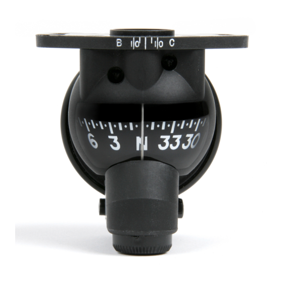
- Page 17 SIRS NAVIGATION LTD COMPONENT MAINTENANCE MANUAL DESCRIPTION AND OPERATION General The compasses (Fig.1) are self-contained magnetic units, installed at eye level or above, and give a constant indication of aircraft direction. CORRECTOR KEY APERTURES MOUNTING PLATE LUBBER LINE COMPASS CARD...
- Page 18 SIRS NAVIGATION LTD COMPONENT MAINTENANCE MANUAL The compass bowl is filled with silicone fluid to control movement of the compass card. Bellows (10) at the rear of the compass bowl, allow fluid volume changes. A filling plug (190), disc (210) and washer (200) are assembled to the compass bowl below the corrector assembly (160).
- Page 19 SIRS NAVIGATION LTD COMPONENT MAINTENANCE MANUAL The compass must be installed with two ‘non-magnetic’ screws, with a head diameter of dimension 6.5mm to 6.9mm. CAUTION: THE SCREWS THAT ATTACH THE COMPASS MUST NOT BE OVER-TIGHTENED. NOTE: Refer to the installation drawing for detailed information.The compass does not need electrical power to operate, other than for illumination.
- Page 20 The document reference is online, please check the correspondence between the online documentation and the printed version.
- Page 21 SIRS NAVIGATION LTD COMPONENT MAINTENANCE MANUAL TESTING & FAULT ISOLATION A. General The contents of this section, identify and recommend solutions to problems which can occur in service. NOTE: A complete performance test procedure must be applied to the compass after adjustment, repair or component replacement, other than the replacement of the ‘filament lamp’...
- Page 22 SIRS NAVIGATION LTD COMPONENT MAINTENANCE MANUAL COMPASS LIGHT IS DEFECTIVE REPLACE FILAMENT LAMP (360) MEASURE THE POWER FILAMENT LAMP SUPPLY CONTINUITY AND OPERATES REPAIR IF FAULTY ‘FILAMENT LAMP’ OPERATES EXAMINE THE ELECTRICAL CONTINUITY BETWEEN THE TWO CONNECTORS OF THE ‘LIGHT ASSEMBLY’.
- Page 23 SIRS NAVIGATION LTD COMPONENT MAINTENANCE MANUAL (iii) Slow Movement of the Compass Card The compass card will move slowly during aircraft direction changes and the card can become fixed. Follow the procedure below if the compass card has slow movement.
- Page 24 SIRS NAVIGATION LTD COMPONENT MAINTENANCE MANUAL The procedure detailed below must be followed if ‘magnetic correction’ problems are identified. NOTE: Before you do these tests, refer to the ‘Installation Instructions’. Remove the compass from the aircraft. Adjust the magnetic correctors to their neutral-effect alignment – (Ref. Fig.11001).
- Page 25 SIRS NAVIGATION LTD COMPONENT MAINTENANCE MANUAL PERFORMANCE TESTING 1. General The tests detailed in this section must be performed after overhaul or repair. The tests must be done in an approved magnetic testing facility. The tests must be done in an ambient temperature range of 15 to 25°C.
- Page 26 SIRS NAVIGATION LTD COMPONENT MAINTENANCE MANUAL B. Electrical (1) Remove the cap (250) and lamp (240) from the lamp housing assembly (230). (2) Test the insulation resistance between the two connecting pins of the ‘lamp housing’. The value must not be less than 20 megohms at 500 V D.C.
- Page 27 SIRS NAVIGATION LTD COMPONENT MAINTENANCE MANUAL Directional Errors (Ref. Fig.1003) Adjust the 'B' and 'C' correctors to their neutral-effect alignment (Ref. Fig 11001) i.e. the indicator lines are aligned with the index lines. NOTE: An Alignment error of 0.5mm, i.e. the width of an index line, will cause a deviation error in the compass of approximately 2.5°.
- Page 28 SIRS NAVIGATION LTD COMPONENT MAINTENANCE MANUAL Put the compass into the support stand and put the support stand on the ‘divided test head’. Align the complete ‘test jig’ with magnetic north. Test the compass to find the directional error at each 10° heading. Record the error from the divided test head scale.
- Page 29 SIRS NAVIGATION LTD COMPONENT MAINTENANCE MANUAL G. Magnetic Correctors (1) Align the magnetic correctors to their neutral-effect alignment (Ref. Fig. 11001). (2) Align the compass to North. (3) Turn the 'C' ‘corrector spindle’, with the ‘corrector key’ (220) through 90°, i.e. the indicator lines must be at 90°...
- Page 30 SIRS NAVIGATION LTD COMPONENT MAINTENANCE MANUAL J. Parallax (1) Align the compass to North. (2) Look at the compass at an angle of 22.5° from the front. The value, between the ‘lubber line’ and the ‘card must be North ± 2.5° left and right of the lubber line.
- Page 31 SIRS NAVIGATION LTD COMPONENT MAINTENANCE MANUAL DISASSEMBLY 1. General The work must be done in a clean environment. 2. Tools and Equipment Non Magnetic Screwdrivers, clean glass container (up to 100ml). 3. Procedure A. Corrector Assembly (160) (1) Remove the four screws (170) from the corrector assembly (160).
- Page 32 SIRS NAVIGATION LTD COMPONENT MAINTENANCE MANUAL C. Stem Assembly (80) and Compass Card (130) CAUTION: THE STEM ASSEMBLY AND COMPASS CARD ASSEMBLY ARE DELICATE ITEMS. BE CAREFUL NOT TO CAUSE DAMAGE. NOTE: When you do this procedure, hold the ‘stem bracket’, the assembly will move when the screws are removed.
- Page 33 SIRS NAVIGATION LTD COMPONENT MAINTENANCE MANUAL CLEANING General Items necessary for the cleaning procedures are detailed in Table 4001 below. Nomenclature Vendor Silicone fluid SIRS Navigation Ltd, (Viscosity 3 cs ± 10%). Electrical Cleaner (Ambersil FE10) NATO Code: 6850-99-6636478 Grease...
- Page 34 SIRS NAVIGATION LTD COMPONENT MAINTENANCE MANUAL C. Lamp Housing (230) (1) Clean the lamp housing electrical components and circuit board with a small brush, made moist with electrical cleaner. (2) Dry with a jet of clean, dry air. D. Compass Bowl (180) CAUTION: DO NOT USE SOLVENT CLEANING FLUIDS TO CLEAN THE COMPASS BOWL.
- Page 35 SIRS NAVIGATION LTD COMPONENT MAINTENANCE MANUAL INSPECTION / CHECKS 1. General These procedures also apply to new components. A. All Components Examine, as applicable, for: Clean condition of components. Shape. Cracks. Corrosion. Surface finish. Wear. B. Electrical Components Examine for: Deterioration of wiring and insulation.
- Page 36 SIRS NAVIGATION LTD COMPONENT MAINTENANCE MANUAL B. Stem Assembly (80) Examine the ‘sapphire bearing cup’ of the ‘Stem Assembly’ (80). The cup must be free from cracks, flaws and surface damage. The conical section of the cup holder must be free from burrs or contamination.
- Page 37 SIRS NAVIGATION LTD COMPONENT MAINTENANCE MANUAL E. Corrector Assembly (160) (1) Use the corrector key to turn the corrector mechanisms two or three turns; they must turn smoothly but with sufficient friction to prevent them moving from shock or vibration.
- Page 38 SIRS NAVIGATION LTD COMPONENT MAINTENANCE MANUAL G. Surface Finish (1) Inspect all paint for signs of deterioration. (2) Repair if necessary as detailed in Page Block 6001 Repair. H. Silicone Fluid (1) If there are signs of cloudiness, sediment or discoloration, discard the fluid.
- Page 39 The new ‘card assembly’ will be supplied magnetised and balanced. Additional balancing can be necessary if the ‘card assembly’ is used in extreme North and South latitudes. Information can be supplied by SIRS Navigation Ltd. B. Lamp Housing Assembly (230) There is no repair procedure specified for this component.
- Page 40 SIRS NAVIGATION LTD COMPONENT MAINTENANCE MANUAL C. Bellows. (10) If the depth of the bellows is less than 8.9mm (0.35”), extend the dimension by running a suitably tapered piece of peg wood round the outer convolutions. If the dimension is greater, gently compress the assembly until the correct dimension is achieved.
- Page 41 A. Magnetising the Compass Card (130) The compass card will be magnetised by the manufacturer to the correct value. SIRS Navigation Ltd., will supply special information if it is necessary for a repair agent to re-magnetise the card. PAGE 7001...
- Page 42 SIRS NAVIGATION LTD COMPONENT MAINTENANCE MANUAL B. Balancing the Compass Card (130) NOTE: The compass card is balanced during manufacture so that the N-S axis dips 0° to 1° at its North-seeking end, i.e. S on the card. This condition applies to latitude 51°...
- Page 43 SIRS NAVIGATION LTD COMPONENT MAINTENANCE MANUAL CAUTION: IN THE PROCEDURE.THAT FOLLOWS, DO NOT MOVE THE BALANCING BOWL Set the micrometer scale on the test head to be zero. Use the standard magnetic needle 3252 LMT, to align the sighting vane with the magnetic meridian.
- Page 44 SIRS NAVIGATION LTD COMPONENT MAINTENANCE MANUAL D. Stem Assembly (80) and Compass Card Assembly (130) (1) Assemble the ‘stem assembly’ (80) to the compass bowl (180) with two non-magnetic screws (90). (2) Assemble the sapphire checking plate 3256 LMT to the the compass bowl with the two knurled screws.
- Page 45 SIRS NAVIGATION LTD COMPONENT MAINTENANCE MANUAL F. Filling (Ref. Fig. 7003) NOTE: The procedure must be done at a temperature of 20°C ± 2°C. Attach the hooked rod of the bellows setting jig 3255 LMT to the lug on the bellows (10).
- Page 46 SIRS NAVIGATION LTD COMPONENT MAINTENANCE MANUAL NOTE: Do the procedure that follows quickly. The filling plug hole must always be covered by silicone fluid. Increase the pressure to atmospheric level. Remove the ‘silicone fluid container’ and assemble the washer (200), disc (210) and filling plug (190). Use the torque screwdriver to tighten the filling plug to a torque of 2880 gf/cm ±...
- Page 47 SIRS NAVIGATION LTD COMPONENT MAINTENANCE MANUAL K. Testing Test the compass as detailed in Page Block 1005 Testing. Silicone Fluid – Filling Rig Figure 7002 PAGE 7007 34-25-21 APR 10/03 The document reference is online, please check the correspondence between the online documentation and the printed version.
- Page 48 The document reference is online, please check the correspondence between the online documentation and the printed version.
- Page 49 COMPONENT MAINTENANCE MANUAL SPECIAL TOOLS, FIXTURES , EQUIPMENT AND MATERIALS 1. General Items are available from SIRS Navigation Ltd. Magnetic materials must be kept away from the test area. All work must be done in a clean environment. 2. Electrical Supplies 5 or 28 V D.C to power the lamp housing assembly (230)
- Page 50 SIRS NAVIGATION LTD COMPONENT MAINTENANCE MANUAL Item Description Part Number or Vendor Reference Vacuum Chamber. Capable of maintaining a pressure of 6.78 Kpa A (2 in. Hg A) Peg-Wood Stick Environmental Chamber with range -40°C to +85°C Bubble Protractor Commercially...
- Page 51 SIRS NAVIGATION LTD COMPONENT MAINTENANCE MANUAL The tools detailed in table 9001 are recommended for the compass adjustment procedure. PART DESCRIPTION SUPPLIER PAGE BLOCK REQUIRED/ COMMENTS NUMBER WHERE USED RECOMENDED CE2-40 CORRECTOR SIRS 11001 REQUIRED SUPPLIED WITH NAVIGATION NEW COMPASS.
- Page 52 The document reference is online, please check the correspondence between the online documentation and the printed version.
- Page 53 SIRS NAVIGATION LTD COMPONENT MAINTENANCE MANUAL STANDBY COMPASS - ILLUSTRATED PARTS LIST WARNING: ONLY USE SPARES AND COMPONENTS SPECIFIED BY SIRS NAVIGATION LTD. Ordering Spares must be ordered with reference to the part number specified in the illustrated parts list.
- Page 54 SIRS NAVIGATION LTD COMPONENT MAINTENANCE MANUAL Compass Illustration Fig. 10001 NOTE: Items 240 and 250 are supplied with item 230. Items 240 and 250 can be supplied independently from item 230 PAGE 10002 34-25-21 APR 10/03 The document reference is online, please check the correspondence between the online documentation and the printed version.
- Page 55 SIRS NAVIGATION LTD COMPONENT MAINTENANCE MANUAL DETAILED PARTS LIST PART NUMBER AIRLINE USAGE UNITS FIG. PART NOMENCLATURE FROM ITEM NUMBER ASSY. KCA0101C OBSOLETE KCA0102C OBSOLETE KCA0102W OBSOLETE KCA0107W OBSOLETE KCA0109W OBSOLETE KCA0110W OBSOLETE KCA0101W COMPASS (MOD 02) KCA0104W COMPASS (MOD 02)
- Page 56 SIRS NAVIGATION LTD COMPONENT MAINTENANCE MANUAL DETAILED PARTS LIST (CONTINUED) FIG. PART NUMBER AIRLINE USAGE UNITS ITEM PART NOMENCLATURE FROM NUMBER ASSY. 130A CE2A128 CARD ASSEMBLY CORRECTOR ASSEMBLY CE2-A129 CORRECTOR ASSEMBLY 160A CE2-A129G (GREY) 910207 SCREW BOWL CE2-117 180A CE2-117G...
- Page 57 SIRS NAVIGATION LTD COMPONENT MAINTENANCE MANUAL DETAILED PARTS LIST (CONTINUED) FIG. PART NUMBER AIRLINE USAG UNITS ITEM PART NOMENCLATURE NUMBER FROM ASSY. LEAD AND SOCKET 260A CE2A52-2 ASSEMBLY (2.5m) ALTERNATIVE LENGTH LEAD AND SOCKET 260B CE2A52-3 ASSEMBLY (11 FT.) ALTERNATIVE LENGTH...
- Page 58 The document reference is online, please check the correspondence between the online documentation and the printed version.
- Page 59 SIRS NAVIGATION LTD COMPONENT MAINTENANCE MANUAL SPECIAL PROCEDURES Compass Magnetic Correction A. General The compass includes a ‘magnetic correction system’, which removes errors caused by mechanical and electrical components of the aircraft. Use the corrector key (220) to adjust the corrector shafts (Ref. Fig. 11001). The key is turned clockwise or anti-clockwise to give approximately 30 to 35°...
- Page 60 SIRS NAVIGATION LTD COMPONENT MAINTENANCE MANUAL C. Removal of Mechanical Alignment Error (index error). 1. Move the aircraft to magnetic heading: North, South, East and West. Aircraft Magnetic Standby Compass Error Heading North 0° East 90° South 180° West 270°...
- Page 61 SIRS NAVIGATION LTD COMPONENT MAINTENANCE MANUAL C. Removal of East-West and North-South Errors. 1. Turn the aircraft to magnetic north (000 ±2°). 2. Turn the C corrector with the corrector key (220) until the compass shows 000°. 3. Remove the corrector key and make sure the compass does not move.
- Page 62 The document reference is online, please check the correspondence between the online documentation and the printed version.
- Page 63 SIRS NAVIGATION LTD COMPONENT MAINTENANCE MANUAL STORAGE INSTRUCTIONS General NOTE: These instructions are applicable to temperate and tropical climates. The packaging is satisfactory for storage and transit purposes. Packaging Procedure 1. Put the Compass unit in a transparent polythene bag together with the corrector Key (220) and electrical lead assembly (260).
- Page 64 SIRS NAVIGATION LTD COMPONENT MAINTENANCE MANUAL C Storage Conditions and Storage Life NOTE: See publication SAV/OH/SPR, available from SIRS Navigation Ltd. i) Storage Conditions 1. The compass must be stored in its primary package 2. The compass must be kept away from all magnetic sources.
Need help?
Do you have a question about the KCA0101C and is the answer not in the manual?
Questions and answers