Table of Contents
Advertisement
Quick Links
The PEGASUS compass of series PG2* is a precision instrument suitable for installation into Light Aircraft. To obtain the optimum performance you should ensure that you carry out the
following instructions carefully. We advise you to read through these instructions and notes before attempting to mount the unit in your aircraft.
THE COMPASS
The PEGASUS is provided with a compensating system, which will enable you to minimise, the magnetic disturbances created by the mechanical and electrical characteristics of your
aircraft.
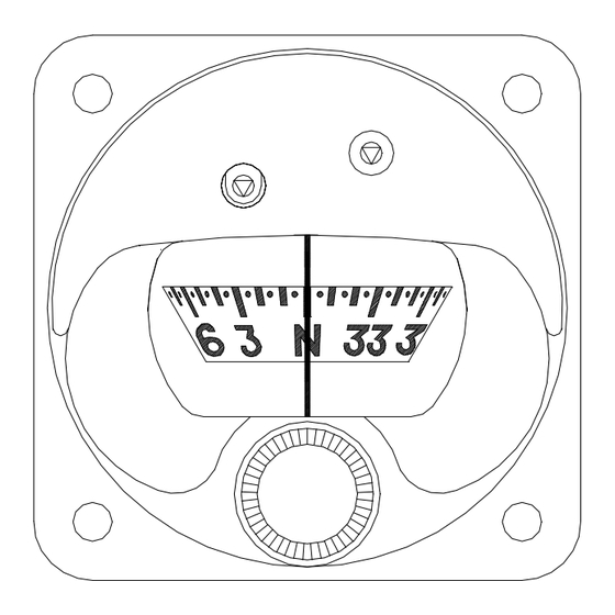
The Compass Card is graduated in 5-degree increments with cardinal points at N, S, E & W. Because of the limited space available, the markings between the cardinal points should be
multiplied by a factor of 10. i.e. 3 = 30 degrees, 24 = 240 degrees etc.
Compass magnetic correction can be achieved by using the special key, provided with the unit, and inserting it either of the two holes located on the front face of the compass. Rotation
of the key will provide 30 degrees of compensation for the main cardinal headings. An indication of the correction setting is seen from the top of the compass.
POSITION
The optimum mounting position for the compass is away from other sources of magnetic disturbance. In some aircraft, the position will be pre-determined and the mounting position will
be where the panel mount hole is sited. If the position of the compass is not already fixed, then positions above the instrument panel are generally more suitable for less magnetic
disturbance.
Before finalising the mounting point, it is a good idea to temporarily mount the compass in its intended position and "Swing" the aircraft to see if the initial deviations are
less than 30 degrees. If the deviation for each cardinal point is less than 30 degrees then proceed with the mounting procedure described below. If the errors are greater than 30
degrees, then try mounting the compass in a more suitable position. If this does not resolve the problem, local de-gaussing may be required to reduce the disturbing magnetic influence.
MOUNTING
1)
To mount the unit follow steps 2 to 4
2)
Close doors, windows, switch on the engine and accessories which are commonly used such as radio, heater fan etc.
3)
Fix the compass in place using 4 screws, ensuring not to over tighten against the front face. The use of an anti-vibration fastener is recommended
4 Clearance Holes of ∅ 4.1mm are provided for the mounting screws.
4)
THE 'PEGASUS' AIRCRAFT COMPASS
From SIRS Navigation Ltd – England.
Installation Instructions
Fig 1
Page 1
N:\DOCUMENT\Word on the server\Manuals\Pegasus Installation Manual.3.doc Iss:2 21/09/11
Advertisement
Table of Contents

Related Manuals for SIRS Navigation Pegasus

Summary of Contents for SIRS Navigation Pegasus
-
Page 1: Installation Instructions
Installation Instructions The PEGASUS compass of series PG2* is a precision instrument suitable for installation into Light Aircraft. To obtain the optimum performance you should ensure that you carry out the following instructions carefully. We advise you to read through these instructions and notes before attempting to mount the unit in your aircraft. - Page 2 If having carried out these procedures the results are not satisfactory a new B (SOUTH) location must be found. Before this can be done, the PEGASUS must be C (EAST) returned to its ZERO correction status by rotating the correctors using the D (WEST) special key.
Need help?
Do you have a question about the Pegasus and is the answer not in the manual?
Questions and answers