Table of Contents
Advertisement
Advertisement
Table of Contents

Related Manuals for Bently Nevada PROXIMITOR 3500/42

Summary of Contents for Bently Nevada PROXIMITOR 3500/42
- Page 1 Artisan Technology Group is your source for quality new and certified-used/pre-owned equipment SERVICE CENTER REPAIRS WE BUY USED EQUIPMENT • FAST SHIPPING AND DELIVERY Experienced engineers and technicians on staff Sell your excess, underutilized, and idle used equipment at our full-service, in-house repair center We also offer credit for buy-backs and trade-ins •...
- Page 2 Part number 129773-01 Revision G, November 1998 3500/42 ® PROXIMITOR /SEISMIC MONITOR MODULE OPERATION AND MAINTENANCE MANUAL Artisan Technology Group - Quality Instrumentation ... Guaranteed | (888) 88-SOURCE | www.artisantg.com...
- Page 3 Fax (702) 782-9259 Copyright infringement is a serious matter under the United States of America and foreign copyright laws. Keyphasor® and Proximitor® are registered trademarks of Bently Nevada Corporation. Artisan Technology Group - Quality Instrumentation ... Guaranteed | (888) 88-SOURCE | www.artisantg.com...
- Page 4 Additional Information Notice: This manual does not contain all the information required to operate and maintain the Proximitor/Seismic Monitor. Refer to the Following manuals for other required information. 3500 Monitoring System Rack Installation and Maintenance Manual (129766-01) • general description of a standard system •...
-
Page 5: Table Of Contents
3500/42 Proximitor/Seismic Monitor Module Contents Receiving and Handling Instructions 1.1 Receiving Inspection 1.2 Handling and Storing Considerations General Information 2.1 Triple Modular Redundant (TMR) Description 2.2 Available Data 2.2.1 Statuses 2.2.2 Proportional Values 2.3 LED Descriptions Configuration Information 3.1 Software Configuration Options 3.1.1 Proximitor/Seismic Monitor Configuration Options 3.1.2 Radial Vibration Channel Options 3.1.3 Thrust Position Channel Options... - Page 6 5.2 Adjusting the Scale Factor and the Zero Position 5.2.1 Adjusting the Scale Factor 5.2.2 Zero Position Adjustment Description 5.2.3 Adjusting the Zero Position Troubleshooting 6.1 Self-test 6.2 LED Fault Conditions 6.3 System Event List Messages 6.4 Alarm Event List Messages Ordering Information Specifications Artisan Technology Group - Quality Instrumentation ...
- Page 7 3500/42 Proximitor/Seismic Monitor Module Artisan Technology Group - Quality Instrumentation ... Guaranteed | (888) 88-SOURCE | www.artisantg.com...
-
Page 8: Receiving And Handling Instructions
Receiving and Handling Instructions Receiving Inspection Visually inspect the module for obvious shipping damage. If shipping damage is apparent, file a claim with the carrier and submit a copy to Bently Nevada Corporation. Handling and Storing Considerations Circuit boards contain devices that are susceptible to damage when exposed to electrostatic charges. -
Page 9: General Information
The monitor can be programmed using the 3500 Rack Configuration Software to perform any of the following functions: Radial Vibration, Thrust Position, Eccentricity, Differential Expansion, Acceleration, and Velocity. The monitor can receive input from many types of transducers including the following Bently Nevada transducers: Proximitor Transducers Acceleration Velocity 7200 5, 8, 11, &... -
Page 10: Triple Modular Redundant (Tmr) Description
3500/42 Operation and Maintenance General Information I/O Modules with Barriers Internal Proximitor Barrier I/O Module, Internal Termination, refer to Section 4.3 Internal Prox/Seismic Barrier I/O Module, Internal Termination, refer to Section 4.3 Internal Seismic Barrier I/O Module, Internal Termination, refer to section 4.3 The primary purpose of the 3500/42 monitor is to provide 1) machinery protection by continuously comparing current machine vibration against configured alarm... -
Page 11: Available Data
General Information 3500/42 Operation and Maintenance The second type of voting is referred to as "Comparison" voting. With this type of voting, the proportional value outputs of each monitor in the group are compared with each other. If the output of one monitor differs from the output of the other monitors in the group by a specified amount, that monitor will add an entry to the System Event list. - Page 12 3500/42 Operation and Maintenance General Information Alert/Alarm 1 This indicates whether the monitor has entered Alert/Alarm 1. A monitor will enter the Alert/Alarm 1 state when any proportional value provided by the monitor exceeds its configured Alert/Alarm 1 setpoint. Danger/Alarm 2 This indicates whether the monitor has entered Danger/Alarm 2.
- Page 13 General Information 3500/42 Operation and Maintenance Bypass This indicates that the channel has bypassed alarming for one or more of its proportional values. A channel bypass status may result from the following conditions: - A transducer is not OK, and the channel is configured for Timed OK Channel Defeat.
- Page 14 3500/42 Operation and Maintenance General Information The following table shows where the statuses can be found: Statuses Communication Rack Operator Gateway Module Configuration Display Software Software Monitor OK Monitor Alert/Alarm 1 Monitor Danger/Alarm 2 Monitor Bypass Monitor Configuration Fault Monitor Special Alarm Inhibit Channel OK Channel Alert/Alarm 1 Channel Danger/Alarm 2...
-
Page 15: Proportional Values
General Information 3500/42 Operation and Maintenance 2.2.2 Proportional Values Proportional values are vibration measurements used to monitor the machine. The Proximitor/Seismic Monitor returns the following proportional values: Radial Thrust Differential Vibration Position Expansion Direct * Direct * Direct * 1X Amplitude 1X Phase Lag 2X Amplitude 2X Phase Lag... -
Page 16: Led Descriptions
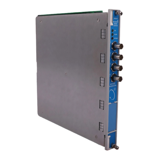
3500/42 Operation and Maintenance General Information LED Descriptions The LED’s on the front panel of the Proximitor/Seismic Monitor indicate the operating status of the module as shown in the following figure. Refer to Section 6.2 (LED Fault Conditions)for all of the available LED conditions. Indicates that the Proximitor/Seismic Monitor and the Proximitor/Seismic I/O Module are operating correctly. -
Page 17: Configuration Information
Configuration Information 3500/42 Operation and Maintenance Configuration Information This section describes how the 3500/42 Proximitor®/Seismic Monitor is configured using the Rack Configuration Software. It also describes any configuration restrictions associated with this module. Refer to the 3500 Monitoring System Rack Configuration and Utilities Guide and the Rack Configuration Software for the details on how to operate the software. - Page 18 3500/42 Operation and Maintenance Configuration Information Reference Information These fields contain information that indicates which module you are configuring. Slot The location of the monitor in the 3500 rack (2 through 15). Rack Type The type of Rack Interface Module installed in the rack (Standard or TMR). Configuration ID A unique six character identifier which is entered when a configuration is downloaded to the 3500 rack.
- Page 19 Configuration Information 3500/42 Operation and Maintenance Prox/Velom Internal Barrier I/O The transducer field wiring is connected directly to the Proximitor/Seismic Monitor Internal Barrier I/O Module. Note that selecting the Prox/Velom Internal Barrier I/O option will disable certain transducer type options. Velom Internal Barrier I/O The transducer field wiring is connected directly to the Proximitor/Seismic Monitor Internal Barrier I/O Module.
- Page 20 3500/42 Operation and Maintenance Configuration Information Channel Pair 1 and 2 Channel Pair 3 and 4 The fields within these boxes pertain to both channels of the channel pair. Channel Pair Type The type of monitoring which is to be performed by the channel pair. The following Channel Pair types are available in the monitor: - Radial Vibration - Thrust Position...
-
Page 21: Radial Vibration Channel Options
Configuration Information 3500/42 Operation and Maintenance Notes: The alarming hysteresis for all channel configurations for a 42 Monitor is 1/64 of Full Scale. When a channel exceeds an alarm setpoint, it must fall back below the setpoint less the hysteresis before it can go out of alarm. For example, consider a channel configuration with a 0–10 mils full scale and an alarm setpoint at 6 mils as illustrated below: The hysteresis = 10 mils/64 = 0.16 mils. - Page 22 3500/42 Operation and Maintenance Configuration Information - There are two selections for 3000 Series transducers: 3000(-24V) Proximitor Select this option when connecting a 3000 Series proximitor directly to a 3500 monitor. A default scale factor of 285 mV/mil will be selected. This may be adjusted ±15 %.
- Page 23 \3500\Rackcfg\Mods\ directory. When a CP Mod file is selected, a window is displayed which describes the function of the modification. CP Mod files are available through Bently Nevada's Custom Products Division. Contact your local Bently Nevada Sales Representative for details.
- Page 24 3500/42 Operation and Maintenance Configuration Information Reference Information These fields contain information that indicates which module you are configuring. Channel The number of the channel being configured (1 through 4). Slot The location of the monitor in the 3500 rack (2 through 15). Rack Type Identifies the type of Rack Interface Module installed in the rack (Standard or TMR).
- Page 25 Configuration Information 3500/42 Operation and Maintenance Not 1X Ampl In a complex vibration signal, notation for the amplitude component that occurs at frequencies other than rotative speed. Ampl Single peak measurement of unfiltered XY (orthogonal) probes, in the measurement planes, against a calculated "quasi zero" point. Only one S Ampl value is returned per channel pair (channel 1 or channel 3).
- Page 26 3500/42 Operation and Maintenance Configuration Information Gap Full Scale Ranges by transducer type 3300–5 mm Proximitor 7200–11 mm Proximitor 3000 (-18V) Proximitor 3300–8 mm Proximitor 7200–14 mm Proximitor 3000 (-24V) Proximitor 7200–5 mm Proximitor 3300–16 mm HTPS 3300 RAM Proximitor 7200–8 mm Proximitor Nonstandard -24 Vdc...
- Page 27 Configuration Information 3500/42 Operation and Maintenance - The transition of a phase measurement that is decreasing occurs at 0 degrees (4 mA). At this point, the recorder signal switches from 4 mA to a signal that corresponds to 360 degrees or 19.158 mA. Delay The time which a proportional value must remain at or above an over alarm level or below an under alarm level before an alarm is declared as active.
- Page 28 3500/42 Operation and Maintenance Configuration Information Trip Multiply The value selected to temporarily increase the alarm (Alert and Danger) setpoint values. This value is normally applied by manual (operator) action during startup to allow a machine to pass through high vibration speed ranges without monitor alarm indications.
- Page 29 Configuration Information 3500/42 Operation and Maintenance Customize button Used to adjust the Scale Factor for transducers. If Non-standard is selected as the transducer type, the OK Limits can also be adjusted. The Non-standard transducer's scale factor must be between 85 and 230 mV/mil. Also, there must be at least 2 volts between the Upper and Lower OK Limits.
- Page 30 3500/42 Operation and Maintenance Configuration Information OK Limits Transducer Upper Lower Center Gap Voltage Without With Without With Without With Barriers Barriers Barriers Barriers Barriers Barriers 3300 8 mm -16.75 -16.75 -2.75 -2.75 -9.75 -9.75 3300 5 mm 7200 5 mm 7200 8 mm 7200 11 mm -19.65...
-
Page 31: Thrust Position Channel Options
Configuration Information 3500/42 Operation and Maintenance Transducer Orientation Degrees The location of the transducer on the machine. The range for orientation angle is 0 to 180 degrees left or right as observed from the driver to the driven end of the machine train. Refer to the following figure: shaft driven end 0°... - Page 32 3500/42 Operation and Maintenance Configuration Information range and the upscale direction. - Monitors must be configured in channel pairs (for example, Channels 1 and 2 may be configured as Thrust Position and Channels 3 and 4 may be configured as Radial Vibration). - When a full-scale range is modified, the setpoints associated with this proportional value should be readjusted.
- Page 33 These files must be located in the \3500\Rackcfg\Mods\ directory. When a CP Mod file is selected, a window is displayed which describes the function of the modification. CP Mod files are available through Bently Nevada's Custom Products Division. Contact your local Bently Nevada Sales Representative for details.
- Page 34 3500/42 Operation and Maintenance Configuration Information Reference Information These fields contain information that indicates which module you are configuring. Channel The number of the channel being configured (1 through 4). Slot The location of the monitor in the 3500 rack (2 through 15). Rack Type Identifies the type of Rack Interface Module installed in the rack (Standard or TMR).
- Page 35 Configuration Information 3500/42 Operation and Maintenance Clamp Value The value that a proportional value goes to when that channel or proportional value is Bypassed or defeated. The selected value can be between the minimum and maximum full-scale range values. Only the values available from the Recorder Outputs, Communication Gateway and Display Interface Module are clamped to the specified value when the proportional value is invalid.
- Page 36 3500/42 Operation and Maintenance Configuration Information Danger Second level alarm that occurs when the transducer signal level exceeds the selected Danger/Alarm 2 setpoint. This setpoint can be set on the Setpoint screen. 100 ms option The 100 ms (typical) option applies to the Danger time delay only and has the following results: If the 100 ms option is off ( - The Danger time delay can be set at one second intervals (from 1...
- Page 37 Configuration Information 3500/42 Operation and Maintenance The following transducer types are available for the Thrust Position Channel (barrier I/O module): 3300 - 5mm Proximitor 3300 - 8mm Proximitor 7200 - 5mm Proximitor 7200 - 8mm Proximitor 3300 RAM Proximitor Nonstandard Customize button Used to adjust the Scale Factor for transducers.
- Page 38 3500/42 Operation and Maintenance Configuration Information Transducer Scale Factor Without With Bently Standard I/O Discrete TMR Bussed TMR Barriers Nevada Internal With I/O With I/O With Barriers Barriers Barriers Barriers 3300 5 and 8 mm 200 mV/mil 200 mV/mil 192 mV/mil 200 mV/mil 199 mV/mil 7200 5 and 8 mm...
- Page 39 Configuration Information 3500/42 Operation and Maintenance Transducer Jumper Status (on I/O Module) Returns the position of the Transducer Jumper on the Proximitor/Seismic I/O Module. Refer to Section 4.1 (Setting the I/O Jumper) for the function of this jumper. Alarm Mode Latching Once an alarm is active it will remain active even after the proportional value drops below the configured setpoint level.
-
Page 40: Differential Expansion Channel Options
3500/42 Operation and Maintenance Configuration Information 3.1.4 Differential Expansion Channel Options This section discusses the Configuration Considerations and the Rack Configuration Software screens associated with the Differential Expansion Channel. 3.1.4.1 Differential Expansion Channel Configuration Considerations Consider the following items before configuring a Differential Expansion Channel: - None of the differential expansion channel transducers are able to support discrete Internal Barrier I/O modules. - Page 41 These files must be located in the \3500\Rackcfg\Mods\ directory. When a CP Mod file is selected, a window is displayed which describes the function of the modification. CP Mod files are available through Bently Nevada's Custom Products Division. Contact your local Bently Nevada Sales Representative for details.
- Page 42 3500/42 Operation and Maintenance Configuration Information Rack Type Identifies the type of Rack Interface Module installed in the rack (Standard or TMR). Enable Direct Change in position of the shaft due to the thermal growth relative to the machine casing. This value may be displayed in inches or mm. This proportional value supports both center zero and noncenter zero Full Scale Ranges.
- Page 43 Configuration Information 3500/42 Operation and Maintenance Recorder Output The proportional value of a channel that is sent to the 4 to 20 mA recorder. The recorder output is proportional to the measured value over the channel full-scale range. An increase in the proportional value that would be indicated as upscale on a bar graph display results in an increase in the current at the recorder output.
- Page 44 3500/42 Operation and Maintenance Configuration Information Danger Second level alarm that occurs when the transducer signal level exceeds the selected Danger/Alarm 2 setpoint. This setpoint can be set on the Setpoint screen. 100 ms option The 100 ms (typical) option applies to the Danger time delay only and has the following results: If the 100 ms option is off ( - The Danger time delay can be set at one second intervals (from 1 to 60).
- Page 45 Configuration Information 3500/42 Operation and Maintenance Customize button Used to adjust the Scale Factor of transducers. If Non-standard is selected as the transducer type, the OK Limits can also be adjusted. The Non-standard transducer's scale factor must be between 8.5 and 23 mV/mil. Also, there must be at least 2 volts between the Upper and Lower OK Limits.
-
Page 46: Eccentricity Channel Options
3500/42 Operation and Maintenance Configuration Information Transducer Jumper Status (on I/O Module) Returns the position of the Transducer Jumper on the Proximitor/Seismic I/O Module. Refer to Section 4.1(Setting the I/O Jumper)for the function of this jumper. Alarm Mode Latching Once an alarm is active, it will remain active even after the proportional value drops below the configured setpoint level. - Page 47 Configuration Information 3500/42 Operation and Maintenance - External barriers are not currently supported with 7200 11 mm, 14 mm, or 3300 16 mm HTPS. - Monitors must be configured in channel pairs (for example Channels 1 and 2 may be configured as Eccentricity and Channels 3 and 4 may be configured as Thrust Position).
- Page 48 These files must be located in the \3500\Rackcfg\Mods\ directory. When a CP Mod file is selected, a window is displayed which describes the function of the modification. CP Mod files are available through Bently Nevada's Custom Products Division. Contact your local Bently Nevada Sales Representative for details.
- Page 49 Configuration Information 3500/42 Operation and Maintenance Instantaneous Crossover The value for shaft rotative speed where the direct eccentricity measurement changes from Direct Max/ Direct Min to instantaneous gap. The value for Instantaneous Crossover must be between 1 and 10 rpm. The physical distance between the face of a proximity probe tip and the observed surface.
- Page 50 3500/42 Operation and Maintenance Configuration Information The Gap values are the same for all transducer types. -24 Vdc Custom Clamp Value The value that a proportional value goes to when that channel or proportional value is bypassed or defeated (For example when a problem occurs with the transducer).
- Page 51 Configuration Information 3500/42 Operation and Maintenance If the 100 ms option is on ( - The Danger time delay is set to 100 ms. - The Danger time delay can only be set for the primary proportional value. Direct Channel Above 600 RPM Disabled Display and alarming of the Direct proportional value will be disabled when the shaft rotative speed exceeds 600 rpm.
- Page 52 3500/42 Operation and Maintenance Configuration Information Customize button Used to adjust the Scale Factor for transducers. If Non-standard is selected as the transducer type, the OK Limits can also be adjusted. The Non-standard transducer's scale factor must be between 85 and 230 mV/mil. Also, there must be at least 2 volts between the Upper and Lower OK Limits.
- Page 53 Configuration Information 3500/42 Operation and Maintenance Scale Factor Transducer Without With Bently Standard I/O Discrete TMR Bussed TMR Barriers Nevada Internal With I/O With I/O With Barriers Barriers Barriers Barriers 3300 5 and 8 mm 200 mV/mil 200 mV/mil 192 mV/mil 200 mV/mil 199 mV/mil 7200 5 and 8 mm...
-
Page 54: Acceleration Channel Options
3500/42 Operation and Maintenance Configuration Information Nonlatching When an alarm is active, it will go inactive as soon as the proportional value drops below the configured setpoint level. Alert should be the first level alarm that occurs when the transducer signal level exceeds the selected value. - Page 55 Configuration Information 3500/42 Operation and Maintenance may be configured as Acceleration and Channels 3 and 4 may be configured as Radial Vibration). - When a full-scale range is modified, the setpoints associated with this proportional value should be readjusted. - If a Non-Standard transducer is selected, the setpoint OK limits are set to ±1 volt from the Upper and Lower OK limits that are selected.
- Page 56 These files must be located in the \3500\Rackcfg\Mods\ directory. When a CP Mod file is selected, a window is displayed which describes the function of the modification. CP Mod files are available through Bently Nevada's Custom Products Division. Contact your local Bently Nevada Sales Representative for details.
- Page 57 Configuration Information 3500/42 Operation and Maintenance Reference Information These fields contain information that indicates which module you are configuring. Channel The number of the channel being configured (1 through 4). Slot The location of the monitor in the 3500 rack (2 through 15). Rack Type Identifies the type of Rack Interface Module installed in the rack (Standard or TMR).
- Page 58 3500/42 Operation and Maintenance Configuration Information Direct Full Scale Ranges by transducer type 23733-03 Std Acceleration 49578-01 Std Acceleration 330425 Std Integral Interface Module Interface Module Accelerometer 24145-02 Hi Freq 155023-01 Hi Freq Acceleration Interface Acceleration Interface Module Module 330400 Std Integral Accelerometer Nonstandard 0-2 g pk...
- Page 59 Configuration Information 3500/42 Operation and Maintenance Integrate When Integrate is enabled, the Direct Full-scale range selections change to the following: Direct values (Integrated) by transducer types 23733-02 Std Acceleration Interface 49578-01 Std Acceleration Interface Module Module 24145-02 Hi Freq Acceleration Interface 155023-01 Hi Freq Acceleration Interface Module Module...
- Page 60 3500/42 Operation and Maintenance Configuration Information Corner Frequencies High-pass Filter A four-pole filter that must be at least two octaves away from the Low-pass Filter. HPF = High-pass Filter; LPF = Low-pass Filter HPF ≤ ( LPF / 4 ) Low-pass Filter A four-pole filter that must be at least two octaves away from the High-pass Filter.
- Page 61 Configuration Information 3500/42 Operation and Maintenance Transducer Selection The following transducer types are available for the Acceleration Channel (non-barrier I/O module): 23733-03 Std Acceleration Interface Module 24145-02 Hi Freq Acceleration Interface Module 330400 Std Integral Accelerometer 330425 Std Integral Accelerometer 49578-01 Std Acceleration Interface Module 155023-01 Hi Freq Acceleration Interface Module Nonstandard...
- Page 62 3500/42 Operation and Maintenance Configuration Information Customize button Used to adjust the Scale Factor for standard transducers. If Non-standard is selected as the transducer type, the Scale Factor and the OK Limits can be adjusted. The Non-standard transducer's scale factor must be between 21.2 and 115 mV/mil.
- Page 63 Configuration Information 3500/42 Operation and Maintenance Transducer Scale Factor Without With Bently Standard I/O Discrete TMR Bussed TMR Barriers Nevada Internal With I/O With I/O With Barriers Barriers Barriers Barriers 23733-03 100 mV/g 100 mV/g 95.6mV/g 100 mV/g 99.4 mV/g 24145-02 100 mV/g 330400...
-
Page 64: Velocity Channel Options
3500/42 Operation and Maintenance Configuration Information Nonlatching When an alarm is active, it will go inactive as soon as the proportional value is no longer in alarm. Alert is the first level alarm that occurs when the transducer signal level exceeds the selected value. - Page 65 Configuration Information 3500/42 Operation and Maintenance - Monitors must be configured in channel pairs (for example, Channels 1 and 2 may be configured as Velocity and Channels 3 and 4 may be configured as Thrust Position). - When integration is selected, the available Direct Full-scale Ranges will change to reflect this.
- Page 66 These files must be located in the \3500\Rackcfg\Mods\ directory. When a CP Mod file is selected, a window is displayed which describes the function of the modification. CP Mod files are available through Bently Nevada's Custom Products Division. Contact your local Bently Nevada Sales Representative for details.
- Page 67 Configuration Information 3500/42 Operation and Maintenance Slot The location of the monitor in the 3500 rack (2 through 15). Rack Type Identifies the type of Rack Interface Module installed in the rack (Standard or TMR). Channel Frequency Support Supported frequency range of the selected transducer which depends upon the number of channels selected.
- Page 68 3500/42 Operation and Maintenance Configuration Information Integrate When Integrate is enabled, the Direct Full-scale Range selections change to the following: The Direct values (Integrated) are available for all transducer types. Full-scale Range – Direct 0-5 mil pp 0-10 mil pp 0-20 mil pp 0-100 µm pp 0-200 µm pp...
- Page 69 Configuration Information 3500/42 Operation and Maintenance Delay The time which a proportional value must remain at or above an alarm level or outside an acceptance region before an alarm is declared as active. Alert First level alarm that occurs when the transducer signal level exceeds the selected value.
- Page 70 3500/42 Operation and Maintenance Configuration Information Customize button Used to adjust the Scale Factor for standard transducers. If Non-standard is selected as the transducer type, the Scale Factor and the OK Limits can be adjusted. The Non-standard transducer's scale factor must be between 90 and 575 mV/mil.
- Page 71 Configuration Information 3500/42 Operation and Maintenance Scale Factor Transducer Without Barriers With BNC Internal With Barriers Barriers 9200 500 mV/(in/s) 500 mV/(in/s) 47633 490 mV/(in/s) 490 mV/(in/s) 86205 477 mV/(in/s) 477 mV/(in/s) Nonstandard 2 wire 145 mV/(in/s) 145 mV/(in/s) Velomitor 100 mV/(in/s) 100 mV/(in/s) 100 mV/(in/s)
- Page 72 3500/42 Operation and Maintenance Configuration Information Velocity Channel Options Screen for Channel B Alarm Mode Latching Once an alarm is active it will remain active even after the proportional value is no longer in alarm. The alarm state will continue until the channel is reset. See Page 46.
-
Page 73: Setpoints
Configuration Information 3500/42 Operation and Maintenance OK Mode Latching If a channel is configured for Latching OK, once the channel has gone not OK, the status stays not OK until a reset is issued. See page 47. Nonlatching If a channel is configured for Nonlatching OK, the OK status of that channel will track the defined OK status of the transducer. - Page 74 3500/42 Operation and Maintenance Configuration Information Use the following screen in the Rack Configuration Software to adjust Alert/Alarm 1 and Danger/Alarm 2 setpoints. This screen will vary depending upon the type of channel. Artisan Technology Group - Quality Instrumentation ... Guaranteed | (888) 88-SOURCE | www.artisantg.com...
- Page 75 Configuration Information 3500/42 Operation and Maintenance The following table lists the Alert/Alarm 1 and Danger/Alarm 2 setpoints available for each channel pair type. The setpoint number is used in the Communication Gateway and Display Interface Modules. Setpoint Radial Vibration Thrust Position Differential Number Expansion...
- Page 76 3500/42 Operation and Maintenance Configuration Information Setpoint Eccentricity Acceleration Velocity Number Over Peak to Peak Over Direct Over Direct Over Gap Danger (Over Direct) Danger (Over Direct) Under Gap Over Direct Max Under Direct Max Over Direct Min Under Direct Min Danger (configurable) Danger (configurable) Danger (configurable)
-
Page 77: Software Switches
Configuration Information 3500/42 Operation and Maintenance Software Switches The Proximitor/Seismic Monitor supports two module software switches and four channel software switches. These switches let you temporarily bypass or inhibit monitor and channel functions. Set these switches on the Software Switches screen under the Utilities Option on the main screen of the Rack Configuration Software. - Page 78 3500/42 Operation and Maintenance Configuration Information Monitor Alarm Bypass When enabled, the monitor does not perform alarming functions. All proportional values are still provided. The monitor switch number is used in the Communication Gateway and Display Interface Modules. Monitor Switch Number Switch Name Configuration Mode Monitor Alarm Bypass...
-
Page 79: I/O Module Descriptions
I/O Module Descriptions 3500/42 Operation and Maintenance I/O Module Descriptions The Proximitor®/Seismic I/O Module receives signals from the transducers and routes the signals to the Proximitor/Seismic Monitor. The I/O module supplies power to the transducers. The I/O module also provides a 4 to 20 mA recorder output for each transducer input channels. - Page 80 3500/42 Operation and Maintenance I/O Module Descriptions PROX/ACCL (Proximitor/Accelerometer): The four-pin connector shunt must be installed on the top left four terminal posts. STANDARD Artisan Technology Group - Quality Instrumentation ... Guaranteed | (888) 88-SOURCE | www.artisantg.com...
- Page 81 I/O Module Descriptions 3500/42 Operation and Maintenance SEIS W/O BAR (Seismoprobe without a Barrier): The four-pin connector shunt must be installed on the top right four terminal posts. VELOM (Velomitor): The four-pin connector shunt must be installed on the bottom left four terminal posts.
- Page 82 3500/42 Operation and Maintenance I/O Module Descriptions SEIS W/ BAR (Seismoprobe with Barrier): The four-pin connector shunt must be installed on the bottom right terminal posts. DISCRETE VELOM (Discrete Velomitor): The four-pin connector shunt must be installed on the bottom left four terminal posts.
- Page 83 I/O Module Descriptions 3500/42 Operation and Maintenance BUSSED VELOM (Bussed Velomitor): The four-pin connector shunt must be installed on the bottom right terminal posts. Artisan Technology Group - Quality Instrumentation ... Guaranteed | (888) 88-SOURCE | www.artisantg.com...
-
Page 84: Proximitor/Seismic I/O Module (Internal Termination)
3500/42 Operation and Maintenance I/O Module Descriptions Proximitor/Seismic I/O Module (Internal Termination) Internal Termination I/O modules require you to wire each transducer and recorder directly to the I/O module. This section shows what this Internal Termination I/O module looks like and how to connect the wires to the Euro Style connector. -
Page 85: Proximitor/Seismic Internal Barrier I/O Module (Internal Termination)
I/O Module Descriptions 3500/42 Operation and Maintenance Proximitor/Seismic Internal Barrier I/O Module (Internal Termination) The Internal Barrier I/O modules requires that each transducer be connected to the Barrier I/O module individually. This module provides four channels of intrinsically safe signal conditioning for Proximitor and/or Seismic transducers and has two internally mounted zener barrier modules, one for each pair of transducer channels. -
Page 86: Wiring Euro Style Connectors
3500/42 Operation and Maintenance I/O Module Descriptions Wiring Euro Style Connectors To remove a terminal block from its base, loosen the screws attaching the terminal block to the base, grip the block firmly and pull. Do not pull the block out by its wires because this could loosen or damage the wires or connector. -
Page 87: External Termination I/O Modules
I/O Module Descriptions 3500/42 Operation and Maintenance External Termination I/O Modules External Termination I/O modules let you simplify the wiring to the I/O modules in a 3500 rack by using a 25-pin cable to route the signals from the four transducers and a nine pin cable to route the signals from the recorders to the I/O module. -
Page 88: Proximitor/Seismic Tmr I/O Module (External Termination)
3500/42 Operation and Maintenance I/O Module Descriptions 4.5.2 Proximitor/Seismic TMR I/O Module (External Termination) The Proximitor/Seismic TMR I/O Module is used in a TMR rack and can be configured as TMR I/O Discrete or TMR I/O Bussed. When configured as TMR I/O Discrete, twelve transducers send input signals to three monitors so that each transducer signal of each channel is not shared by other channels. -
Page 89: External Termination Blocks
I/O Module Descriptions 3500/42 Operation and Maintenance 4.5.3 External Termination Blocks The three types of External Termination Blocks used with a Proximitor/Seismic I/O Module are the Proximitor/Seismic External Termination Blocks, the Bussed Proximitor/Seismic External Termination Blocks, and the Recorder External Termination Blocks. - Page 90 3500/42 Operation and Maintenance I/O Module Descriptions 4.5.3.2 Proximitor/Seismic External Termination Block (Euro Style connectors) Connect the wire from the transducers associated with Channel 1, 2, 3, and 4 to the External Termination Block. Connect the I/O module to the External Termination Block using cable 129525-XXXX-XX.
- Page 91 I/O Module Descriptions 3500/42 Operation and Maintenance 4.5.3.3 Bussed Proximitor/Seismic External Termination Block (Terminal Strip connectors) Connect the wire from the transducers associated with Channel 1, 2, 3, and 4 to the External Termination Block. INHB_A/RET_A, INHB_B/RET_B, and INHB_C/RET_C: Connect to a common switch or individual switches.
- Page 92 3500/42 Operation and Maintenance I/O Module Descriptions 4.5.3.4 Bussed Proximitor/Seismic External Termination Block (Euro Style connectors) Channel 1 and Channel 2 Channel 3 and Channel 4 Connect the wire from the transducers associated with Channel 1, 2, 3, and 4 to the External Termination Block.
- Page 93 I/O Module Descriptions 3500/42 Operation and Maintenance 4.5.3.5 Recorder External Termination Block (Terminal Strip connectors) Connect the recorders associated with Channel 1, 2, 3, and 4 to the Recorder External Termination Block. Connect the I/O module to the Recorder External Termination Block using cable 129529-XXXX-XX.
- Page 94 3500/42 Operation and Maintenance I/O Module Descriptions 4.5.3.6 Recorder External Termination Block (Euro Style connectors) Connect the recorders associated with Channel 1, 2, 3, and 4 to the Recorder External Termination Block. Connect the I/O module to the Recorder External Termination Block using cable 129529-XXXX-XX.
-
Page 95: Cable Pin Outs
I/O Module Descriptions 3500/42 Operation and Maintenance 4.5.4 Cable Pin Outs Cable Number 129525-XXXX-XX 3500 Transducer Signal to External Termination Block Cable Artisan Technology Group - Quality Instrumentation ... Guaranteed | (888) 88-SOURCE | www.artisantg.com... - Page 96 3500/42 Operation and Maintenance I/O Module Descriptions 129529-XXXX-XX 3500 Recorder Output to ET Block Cable Artisan Technology Group - Quality Instrumentation ... Guaranteed | (888) 88-SOURCE | www.artisantg.com...
-
Page 97: Maintenance
Maintenance 3500/42 Operation and Maintenance Maintenance The boards and components inside of 3500 modules cannot be repaired in the field. Maintaining a 3500 rack consists of testing module channels to verify that they are operating correctly. Modules that are not operating correctly should be replaced with a spare. -
Page 98: Choosing A Maintenance Interval
- Function Generator - 100 µF capacitor - 40 kΩ resistor - Bently Nevada Corporation TK 16 Keyphasor Multiplier/Divider or equivalent (Instructions in this manual refer to the TK 16) - additional -18 Vdc Supply for use with the TK 16... -
Page 99: Typical Verification Test Setup
Maintenance 3500/42 Operation and Maintenance Velocity Channels - Velomitor - Power Supply (single channel) - Multimeter - 4½ digits - Function Generator - 10 µF capacitor - 4 kΩ resistor Acceleration Channels - Power Supply (single channel) - Multimeter - 4½ digits - Function Generator 5.1.3 Typical Verification Test Setup... -
Page 100: Using The Rack Configuration Software
3500/42 Operation and Maintenance Maintenance Transducers can be connected to a 3500 rack in a variety of ways. Depending on the wiring option for the I/O module of your monitor, connect the test equipment to the monitor using one of the following methods: Connect test equipment here. - Page 101 Maintenance 3500/42 Operation and Maintenance The following figures show how the Verification screen displays output from a 3500 rack: Alarm Verification Fields: These fields display output for verifying channel alarms. Alert/Alarm 1 alarms are displayed in yellow in the bar graph and with the word “Alarm” under the current value box.
- Page 102 3500/42 Operation and Maintenance Maintenance Any channel bar graph value that enters Alert/Alarm 1 or Danger/Alarm 2 will cause the alarm lines in the Channel Status box to indicate an alarm. Any channel that enters alarm will cause the alarm lines in the Module Status box to indicate an alarm.
-
Page 103: Radial Vibration Channels
Maintenance 3500/42 Operation and Maintenance 5.1.5 Radial Vibration Channels The following sections describe how to test alarms, verify channels, and test OK limits for channels configured as Radial Vibration. The output values and alarm setpoints are verified by varying the input vibration signal level (both peak to peak amplitude and DC voltage bias) and observing that the correct results are reported in the Verification screen on the test computer. - Page 104 3500/42 Operation and Maintenance Maintenance Application Alert Disconnecting the field wiring will cause a not OK condition. Test Equipment Setup - Radial Vibration Simulate the transducer signal by connecting the power supply, function generator, and multimeter to COM and SIG of channel 1 with polarity as shown in the figure below (Radial Vibration Test Setup).
- Page 105 Maintenance 3500/42 Operation and Maintenance The equipment shown in the dashed box is required for 1X Amplitude and Phase, 2X Amplitude and Phase, Not 1X Amplitude, and S Amplitude. Keyphasor Multiplier/Divider Keyphasor® I/O Module 100 µF 40 kΩ Keyphasor® Signal Function Generator Multimeter Proximitor®...
- Page 106 3500/42 Operation and Maintenance Maintenance Verification Screen Setup - Radial Vibration Run the Rack Configuration Software on the test computer. Choose Verification from the Utilities menu and choose the proper Slot number and Channel number then click on the Verify button. Note Timed OK Channel Defeat is enabled for Radial Vibration channels.
- Page 107 Maintenance 3500/42 Operation and Maintenance 5.1.5.2 Test Alarms - Radial Vibration The general approach for testing alarm setpoints is to simulate the vibration and Keyphasor® signal with a function generator. The alarm levels are tested by varying the vibration signal (both peak to peak amplitude and DC voltage bias) and observing that the correct results are reported in the Verification screen on the test computer.
- Page 108 3500/42 Operation and Maintenance Maintenance still indicates an Alarm. 9. Adjust the function generator amplitude such that the signal reads below the Over Alarm setpoint levels. If the nonlatching option is configured, observe that the bar graph indicator for Direct changes color to green and that the Current Value Box contains no indication of alarms.
- Page 109 Maintenance 3500/42 Operation and Maintenance 9. Adjust the power supply voltage such that the signal reads below the Over Alarm setpoint levels. If the nonlatching option is configured, observe that the bar graph indicator for Gap changes color to green and that the Current Value Box contains no indication of alarms.
- Page 110 3500/42 Operation and Maintenance Maintenance 7. Adjust the function generator amplitude such that the signal just exceeds the 1X Ampl Over Danger/Alarm 2 setpoint level. Wait for 2 to 3 seconds after the alarm time delay expires and verify that the bar graph indicator for 1X Ampl changes color from yellow to red and the Current Value Field indicates an Alarm.
- Page 111 Maintenance 3500/42 Operation and Maintenance Note The 1X Amplitude needs to be a minimum of 100 mV to get a valid 1X Phase reading. 4. Press the RESET switch on the Rack Interface Module (RIM). Verify that the OK LED is on, the bar graph indicator for 1X Phase is green, and the Current Value field contains no alarm indication.
- Page 112 3500/42 Operation and Maintenance Maintenance 2X Amplitude (2X Ampl) Note The Keyphasor must be triggering and have a valid rpm value to check this parameter. 1. Disconnect PWR, COM, and SIG field wiring from the channel terminals on the I/O module. 2.
- Page 113 Maintenance 3500/42 Operation and Maintenance 11. If you can not verify any configured alarm, recheck the configured setpoints. If the monitor still does not alarm properly or fails any other part of this test, go to Section 5.1.11 (If a Channel Fails a Verification Test). 12.
- Page 114 3500/42 Operation and Maintenance Maintenance 8. Press the RESET switch on the Rack Interface Module (RIM). Verify that the bar graph indicator for 2X Phase remains red and that the Current Value Field still indicates an Alarm. 9. Adjust the phase such that the reading is below the Over Alarm setpoint levels.
- Page 115 Maintenance 3500/42 Operation and Maintenance 6. Press the RESET switch on the Rack Interface Module (RIM). Verify that the bar graph indicator for Not 1X remains yellow and that the Current Value Field still indicates an Alarm. 7. Adjust the function generator amplitude such that the signal just exceeds the Not 1X Over Danger/Alarm 2 setpoint level.
- Page 116 3500/42 Operation and Maintenance Maintenance 5. Adjust the function generator amplitude such that the signal just exceeds the Over Alert/Alarm 1 setpoint level. Wait for 2 or 3 seconds after the alarm time delay expires and verify that the bar graph indicator for S changes color from green to yellow and that the Current Value Field indicates an Alarm.
- Page 117 Maintenance 3500/42 Operation and Maintenance 5.1.5.3 Verify Channel Values - Radial Vibration The general approach for testing channel values is to simulate the vibration and Keyphasor input signal with a function generator. The output values are verified by varying the input vibration signal level (both peak to peak amplitude and DC voltage bias) and observing that the correct results are reported in the Verification screen on the test computer.
- Page 118 3500/42 Operation and Maintenance Maintenance Example 2: Direct Meter Top Scale = 200 µm Transducer Scale Factor = 7,874 mV/mm = 7.874 mV/µm Full Scale = (200 × 0.007874) = 1.5748 Vpp For Vrms input: Vrms = (0.707/2) × (Vpp), for a sinewave input = (0.707/2) ×...
- Page 119 Maintenance 3500/42 Operation and Maintenance If Gap is configured to read in displacement units, calculate the full-scale and bottom-scale voltage using the following equation: Note Use the Transducer Scale Factor displayed in the Scale Factor Box on the Verification Screen. Gap Full-Scale = Gap Zero Position Volts + (Gap Meter Top Scale ×...
- Page 120 3500/42 Operation and Maintenance Maintenance 6. Adjust the power supply to produce a voltage equal to top scale (from step 3) on the Gap bar graph display. Verify that the Gap bar graph display and Current Value Box is reading ±1 % of top scale. If the recorder output is configured, refer to Section 5.1.10 (Verify Recorder Outputs) for steps to verify recorder output.
- Page 121 Maintenance 3500/42 Operation and Maintenance Example 1: 1X Ampl Meter Top Scale = 10 mil Transducer Scale Factor = 200 mV/mil = (10 × 0.200) Full Scale = 2.000 Vpp For V rms input: V rms = (0.707/2) × (Vpp), for a sinewave input = (0.707/2) ×...
- Page 122 3500/42 Operation and Maintenance Maintenance 1X Phase Note If the test equipment is not capable of changing the phase output to a known value, use the following procedure. If your test equipment can change the phase output to a known value, use the procedure on page 116. 1.
- Page 123 Maintenance 3500/42 Operation and Maintenance Interface Module (RIM) to reset the OK LED. 6. Repeat steps 1 through 5 for all configured channels. Note If the test equipment has the capability to change the phase output to a known value, use the following procedures. 1.
- Page 124 3500/42 Operation and Maintenance Maintenance Note Use the Transducer Scale Factor displayed in the Scale Factor Box on the Verification Screen. Example 1: 2X Ampl Meter Top Scale = 10 mil Transducer Scale Factor = 200 mV/mil = (10 × 0.200) Full Scale = 2.000 Vpp For V rms input:...
- Page 125 Maintenance 3500/42 Operation and Maintenance 2X Phase Note If the test equipment is not capable of changing the phase output to a known value, use the following procedure. If your test equipment can change the phase output to a known value, use the procedure on page 119. 1.
- Page 126 3500/42 Operation and Maintenance Maintenance Note If the test equipment has the capability to change the phase output to a known value, use the following procedure. 1. Disconnect PWR, COM, and SIG field wiring from the channel terminals on the I/O module. 2.
- Page 127 Maintenance 3500/42 Operation and Maintenance Full-Scale Voltage = Not 1X Ampl Meter Top Scale × Transducer Scale Factor Note Use the Transducer Scale Factor displayed in the Scale Factor Box on the Verification Screen. Example 1: Not 1X Ampl Meter Top Scale = 10 mil Transducer Scale Factor = 200 mV/mil = (10 ×...
- Page 128 3500/42 Operation and Maintenance Maintenance Amplitude Note The Keyphasor must be triggering and have a valid rpm value to check this parameter. 1. Disconnect PWR, COM, and SIG field wiring from the channel pair terminals on the I/O module. 2. Connect test equipment and run software as described in Section 5.1.5.1 (Test Equipment and Software Setup - Radial Vibration).
- Page 129 Maintenance 3500/42 Operation and Maintenance 4. Set the Keyphasor multiplier/divider so that the multiply setting is set to one and the divide setting is set to one. Adjust the function generator amplitude for full scale. Verify that the S bar graph display and Current Value Box is reading ±1 % of full scale.
- Page 130 3500/42 Operation and Maintenance Maintenance 7. Increase the power supply voltage (more negative) until the OK LED just goes off (upper limit). Verify that the Channel OK State line in the Channel Status box reads not OK and that the OK Relay indicates not OK. Verify that the Upper OK limit voltage displayed on the Verification screen is equal to or more positive than the input voltage.
- Page 131 Maintenance 3500/42 Operation and Maintenance Radial Vibration Default OK Limits Table Transducer Lower OK Limit (volts) Upper OK Limit (volts) 7200 5&8 mm w/ -2.7 to -2.8 -16.7 to -16.8 barriers 7200 5&8 mm w/o -2.7 to -2.8 -16.7 to -16.8 barriers 7200 11 mm w/o -3.5 to -3.6...
-
Page 132: Thrust Position And Differential Expansion Channels
3500/42 Operation and Maintenance Maintenance 5.1.6 Thrust Position and Differential Expansion Channels The following sections describe how to test alarms, verify channels, and test OK limits for channels configured as Thrust Position and Differential Expansion. The output values and alarm setpoints are verified by varying the input DC voltage from a power supply and observing that the correct results are reported in the Verification screen on the test computer. - Page 133 Maintenance 3500/42 Operation and Maintenance Test Equipment Setup - Thrust Position and Differential Expansion Simulate the transducer signal by connecting power supply (output terminals) and multimeter (input terminals) to COM and SIG of channel 1 with polarity as shown in the figure on page 126 (Thrust Position and Differential Expansion Test Setup).
- Page 134 3500/42 Operation and Maintenance Maintenance Verification Screen Setup - Thrust Position and Differential Expansion Run the Rack Configuration Software on the test computer. Choose Verification from the Utilities menu and choose the proper Slot number and Channel number then click on the Verify button. The following table directs you to the starting page of each maintenance section associated with the Thrust Position and Differential Expansion Channels.
- Page 135 Maintenance 3500/42 Operation and Maintenance time delay expires and verify that the bar graph indicator for Direct changes color from green to yellow and that the Current Value Field indicates an Alarm. 6. Press the RESET switch on the Rack Interface Module (RIM). Verify that the bar graph indicator for Direct remains yellow and that the Current Value Field still indicates an Alarm.
- Page 136 3500/42 Operation and Maintenance Maintenance Value field has no alarm indication. 5. Adjust the power supply voltage such that the signal just exceeds the Gap Over Alert/Alarm 1 setpoint level. Wait for 2 or 3 seconds until the alarm time delay expires and verify that the bar graph indicator for Gap changes color from green to yellow and that the Current Value Field indicates an Alarm.
- Page 137 Maintenance 3500/42 Operation and Maintenance 2. Connect test equipment and run software as described in Section 5.1.6.1 (Test Equipment and Software Setup - Thrust Position and Differential Expansion). 3. Calculate the full-scale and bottom scale values. These values can be calculated in the following way: Full-scale Value, Bottom Scale Value = Zero Position Voltage ±...
- Page 138 3500/42 Operation and Maintenance Maintenance Example 2: Transducer scale factor = 7,874 mV/mm Meter scale range = 1-0-1 mm Zero Position Voltage = -10.16 Vdc = (-10.16) + (7.874 × 1) Full Scale Value = -2.286 Vdc Bottom Scale Value = (-10.16) - (7.874 × 1) = -18.03 Vdc If Upscale direction (Normal for Thrust, Long for Differential Expansion) is away from the probe:...
- Page 139 Maintenance 3500/42 Operation and Maintenance 6. Adjust the power supply voltage for the calculated bottom scale. Verify that the Direct bar graph display and the Current Value Box is reading ±1 % of bottom scale. If the recorder output is configured, refer to Section 5.1.10 (Verify Recorder Outputs) for steps to verify the recorder output.
- Page 140 3500/42 Operation and Maintenance Maintenance channel not OK condition and the OK Relay to change state (de-energize). The Upper and Lower OK limits are displayed in the Verification screen on the test computer. 1. Disconnect PWR, COM, and SIG field wiring from the channel terminals on the I/O module.
- Page 141 Maintenance 3500/42 Operation and Maintenance 13. If you can not verify any configured OK limit, go to Section 5.1.11 (If a Channel Fails a Verification Test). 14. Disconnect the test equipment and reconnect the PWR, COM, and SIG field wiring to the channel terminals on the Monitor I/O Module. Press the RESET switch on the Rack Interface Module (RIM) and verify that the OK LED comes on and the OK relay energizes.
-
Page 142: Eccentricity Channels
3500/42 Operation and Maintenance Maintenance Differential Expansion Default OK Limits Table Transducer Lower OK Limit Upper OK Limit (volts) (volts) 25 mm w/o barriers -1.30 to -1.40 -12.5 to -12.6 35 mm w/o barriers -1.30 to -1.40 -12.5 to -12.6 50 mm w/o barriers -1.30 to -1.40 -12.5 to -12.6... - Page 143 Maintenance 3500/42 Operation and Maintenance Application Alert WARNING High voltage present. Tests will exceed alarm Contact could cause setpoint levels causing shock, burns, or death. alarms to activate. This Do not touch exposed could result in a relay wires or terminals. contact state change.
- Page 144 3500/42 Operation and Maintenance Maintenance Power Supply Proximitor® Seismic I/O Module Multimeter Function Generator Keyphasor® I/O Module 100 µF 40 kΩ Keyphasor® Signal Eccentricity Test Setup The Test Equipment outputs should be floating relative to earth ground. Artisan Technology Group - Quality Instrumentation ... Guaranteed | (888) 88-SOURCE | www.artisantg.com...
- Page 145 Maintenance 3500/42 Operation and Maintenance Verification Screen Setup - Eccentricity Run the Rack Configuration Software on the test computer. Choose Verification from the Utilities menu and choose the proper Slot number and Channel number then click on the Verify button. Note If the Timed OK Channel Defeat is enabled, the OK LED will not come on immediately after you connect the test equipment.
- Page 146 3500/42 Operation and Maintenance Maintenance Peak to Peak 1. Disconnect PWR, COM, and SIG field wiring from the channel terminals on the I/O module. 2. Connect test equipment and run software as described in Section 5.1.7.1 (Test Equipment and Software Setup - Eccentricity). 3.
- Page 147 Maintenance 3500/42 Operation and Maintenance 12. Repeat steps 1 through 11 for all configured channels. 1. Disconnect PWR, COM, and SIG field wiring from the channel terminals on the I/O module. 2. Connect test equipment and run software as described in section 5.1.7.1 (Test Equipment and Software Setup - Eccentricity).
- Page 148 3500/42 Operation and Maintenance Maintenance 12. Disconnect the test equipment and reconnect the PWR, COM, and SIG field wiring to the channel terminals on the I/O module. Verify that the OK LED comes on and the OK relay energizes. Press the RESET switch on the Rack Interface Module (RIM) to reset the OK LED.
- Page 149 Maintenance 3500/42 Operation and Maintenance 10. Repeat steps 3 through 9 to test the Under Alert/Alarm 1 and Under Danger/Alarm 2 setpoints by adjusting the power supply to exceed the Under Alarm setpoint levels. 11. If you can not verify any configured alarm, recheck the configured setpoints. If the monitor still does not alarm properly or fails any other part of this test, go to Section 5.1.11 (If a Channel Fails a Verification Test).
- Page 150 3500/42 Operation and Maintenance Maintenance Example 1: Peak to Peak Meter Top Scale = 10 mil Transducer Scale Factor = 200 mV/mil = (10 × 0.200) Full Scale = 2.000 Vpp For Vrms input: = (0.707/2) × (Vpp), for a sinewave input Vrms = (0.707/2) ×...
- Page 151 Maintenance 3500/42 Operation and Maintenance 3. Adjust the power supply to produce a voltage equal to -18.00 Vdc on the Gap bar graph display. Verify that the Gap bar graph display and the Current Value Box is reading ±1 % of -18.00 Vdc. If the recorder output is configured, refer to Section 5.1.10 (Verify Recorder Outputs) for steps to verify the recorder output.
- Page 152 3500/42 Operation and Maintenance Maintenance Note Use the Transducer Scale Factor displayed in the Scale Factor Box on the Verification Screen. Full Scale = (Zero Position Voltage) - (Transducer Scale Factor × Top Meter Scale) Bottom Scale = (Zero Position Voltage) + (Transducer Scale Factor × ABS (Bottom Meter Scale)) Example 1: Transducer scale factor = 200 mV/mil...
- Page 153 Maintenance 3500/42 Operation and Maintenance 7. If the reading does not meet specifications, check that the input signal is correct. If the monitor still does not meet specifications or fails any other part of this test, go to Section 5.1.11 (If a Channel Fails a Verification Test). 8.
- Page 154 3500/42 Operation and Maintenance Maintenance 9. Press the RESET switch on the Rack Interface Module (RIM). Verify that the OK LED comes back on and the OK relay energizes and that the Channel OK State line in the Channel Status box reads OK. 10.
-
Page 155: Velocity Channels
Maintenance 3500/42 Operation and Maintenance Eccentricity Default OK Limits Table Transducer Lower OK Limit Upper OK Limit (volts) (volts) 7200 5 & 8 mm w/ barriers -2.70 to -2.80 -16.70 to -16.80 7200 5 & 8 mm w/o barriers -2.70 to -2.80 -16.70 to -16.80 7200 11 mm w/o barriers -3.50 to -3.60... - Page 156 3500/42 Operation and Maintenance Maintenance Application Alert WARNING High voltage present. Tests will exceed alarm Contact could cause setpoint levels causing shock, burns, or death. alarms to activate. This Do not touch exposed could result in a relay wires or terminals. contact state change.
- Page 157 Maintenance 3500/42 Operation and Maintenance Test Equipment Setup - Velomitor (TMR I/O) Simulate the transducer signal by connecting the power supply, function generator, and multimeter to COM / A and SIG / B of channel 1 with polarity as shown in the figure on page 153 (Velomitor Test Setup TMR I/O). Set the test equipment as specified below.
- Page 158 3500/42 Operation and Maintenance Maintenance Multimeter Function Generator 4 kΩ 10 µF Velomitor Test Setup With Standard I/O The Test Equipment outputs should be floating relative to earth ground. Artisan Technology Group - Quality Instrumentation ... Guaranteed | (888) 88-SOURCE | www.artisantg.com...
- Page 159 Maintenance 3500/42 Operation and Maintenance Multimeter Power Supply Test Setup for Verifying the OK Limits of a Velomitor With Standard I/O. The Test Equipment outputs should be floating relative to earth ground. Artisan Technology Group - Quality Instrumentation ... Guaranteed | (888) 88-SOURCE | www.artisantg.com...
- Page 160 3500/42 Operation and Maintenance Maintenance Multimeter Function Generator 2.74 kΩ 10 µF Velomitor Test Setup With TMR I/O The Test Equipment outputs should be floating relative to earth ground. Artisan Technology Group - Quality Instrumentation ... Guaranteed | (888) 88-SOURCE | www.artisantg.com...
- Page 161 Maintenance 3500/42 Operation and Maintenance Multimeter Power Supply Test Setup for Verifying the OK Limits of a Velomitor With TMR I/O The Test Equipment outputs should be floating relative to earth ground. Artisan Technology Group - Quality Instrumentation ... Guaranteed | (888) 88-SOURCE | www.artisantg.com...
- Page 162 3500/42 Operation and Maintenance Maintenance Verification Screen Setup - Velocity Run the Rack Configuration Software on the test computer. Choose Verification from the Utilities menu and choose the proper Slot number and Channel number then click on the Verify button. Note If the Timed OK Channel Defeat is enabled, it will take 30 seconds for a channel to return to the OK status from not OK.
- Page 163 Maintenance 3500/42 Operation and Maintenance Direct 1. Disconnect PWR / B, COM, and SIG / A (PWR, COM / A, and SIG / B for TMR I/O) field wiring from the channel terminals on the I/O module. 2. Connect test equipment: For Seismoprobe: Connect test equipment and run software as described in section 5.1.8.1 (Test Equipment and Software Setup - Velocity), use the setup shown on...
- Page 164 3500/42 Operation and Maintenance Maintenance If a low-pass filter is configured and no high-pass filter is configured, use HPF = 3 Hz If a high-pass filter is configured and no low-pass filter is configured, use LPF = 5,500 Hz Set the frequency of the function generator to this new value. The above is done to obtain a test frequency in the center of the channel frequency range.
- Page 165 Maintenance 3500/42 Operation and Maintenance 11. Disconnect the test equipment and reconnect the PWR / B, COM, and SIG / A (PWR, COM / A, and SIG / B for TMR I/O) field wiring to the channel terminals on the I/O module. Verify that the OK LED comes on and the OK relay energizes.
- Page 166 3500/42 Operation and Maintenance Maintenance 5.1.8.4 Verify Filter Corner Frequencies The general approach for testing these parameters is to simulate the Velocity signal with a function generator and power supply. The corner frequencies are verified by varying the output from the test equipment and observing that the correct results are reported in the Verification screen on the test computer.
- Page 167 Maintenance 3500/42 Operation and Maintenance 5.1.8.5 Calculating Verification Frequency The procedures for verifying channel values and corner frequencies require that you use the following formulas to calculate the verification frequency: Find the center of the Band-pass frequency range. Input the configured High- pass Filter Corner Frequency and the Low-pass Filter Corner Frequency into the formula below: Vibration Frequency = (0.89 ×...
- Page 168 3500/42 Operation and Maintenance Maintenance Full Scale Formulas - No Integration Units To Input RMS Volts To Input Peak to Peak Volts in/s pk (T.S.F x Full-scale) x 0.707 (T.S.F x Full-scale) x 2 mm/s pk (T.S.F x Full-scale) x 0.707 (T.S.F x Full-scale) x 2 in/s rms (T.S.F x Full-scale)
- Page 169 Maintenance 3500/42 Operation and Maintenance Full Scale Formulas - Integration (For the following units: mil pp and µm pp) Input Full scale (English units) Voltage 0.07071 rms) ...
- Page 170 3500/42 Operation and Maintenance Maintenance Example: To calculate the input voltage for a channel with the following configuration: Transducer Scale Factor = 19.69 mV/(mm/s) Full Scale = 100 µm pp HPF = 3 Hz LPF = 3000 Hz Convert Metric units to English units. Scale Factor: 19.69 mV/(mm/s) ×...
- Page 171 Maintenance 3500/42 Operation and Maintenance 5.1.8.7 Test OK Limits - Velocity Note If the Danger Bypass has been activated, then the BYPASS LED will be on. All other channels in the rack must be OK or bypassed for the OK relay to be energized.
- Page 172 3500/42 Operation and Maintenance Maintenance 5. Press the RESET switch on the Rack Interface Module (RIM). Verify that the monitor OK LED is on and that the Channel OK State line in the Channel Status section of the Verification screen reads OK. 6.
- Page 173 Maintenance 3500/42 Operation and Maintenance supply the buffered outputs on the front panel will be inverted in phase and will have a different DC voltage than the input. This will not affect the actual vibration readings in the Monitor. The general approach for testing OK limits is to input a DC voltage and adjust it above the Upper OK limit and below the Lower OK limit.
- Page 174 3500/42 Operation and Maintenance Maintenance 10. Gradually decrease the power supply voltage (less negative) until the OK LED just goes off (upper limit due to the inversion on the I/O Card). Verify that the Channel OK State line in the Channel Status section reads not OK and that the OK Relay indicates not OK.
-
Page 175: Acceleration Channels
Maintenance 3500/42 Operation and Maintenance Velocity Default OK Limits Table Transducer Lower Ok Limit Upper Ok Limit (volts) (volts) 9200 w/ &w/o barriers -2.0 to -2.1 -17.9 to -18.0 86205 w/ & w/o barriers -2.0 to -2.1 -17.9 to -18.0 47633 w/ &... - Page 176 3500/42 Operation and Maintenance Maintenance Application Alert WARNING High voltage present. Tests will exceed alarm Contact could cause setpoint levels causing shock, burns, or death. alarms to activate. This Do not touch exposed could result in a relay wires or terminals. contact state change.
- Page 177 Maintenance 3500/42 Operation and Maintenance Multimeter Function Generator Power Supply Acceleration Test Setup The Test Equipment outputs should be floating relative to earth ground. Verification Screen Setup - Acceleration Run the Rack Configuration Software on the test computer. Choose Verification from the Utilities menu and choose the proper Slot number and Channel number then click on the Verify button.
- Page 178 3500/42 Operation and Maintenance Maintenance The following table directs you to the starting page of each maintenance section associated with the Acceleration Channels. Section Topic Page Number Number 5.1.9.2 Test Alarms - Direct 5.1.9.3 Verify Channels - Direct 5.1.9.4 Verify Filter Corner Frequencies 5.1.9.7 Test OK Limits 5.1.9.2...
- Page 179 Maintenance 3500/42 Operation and Maintenance If a low-pass filter is configured and no high-pass filter is configured, use the following to determine the HPF to use in the formula: If the units are integrated or rms, use a HPF of 10 Hz. For any other configuration, use a HPF of 3 Hz.
- Page 180 3500/42 Operation and Maintenance Maintenance Value Box should contain no indication of Alarms. Press the RESET switch on the Rack Interface Module (RIM) to reset latching alarms. 10. If you can not verify any configured alarm, recheck the configured setpoints. If the monitor still does not alarm properly or fails any other part of this test, go to Section 5.1.11 (If a Channel Fails a Verification Test).
- Page 181 Maintenance 3500/42 Operation and Maintenance 8. Repeat steps 1 through 7 for all configured channels. 5.1.9.4 Verify Filter Corner Frequencies The general approach for testing these parameters is to simulate the Acceleration signal with a function generator and power supply. The corner frequencies are verified by varying the output from the test equipment and observing that the correct results are reported in the Verification screen on the test computer.
- Page 182 3500/42 Operation and Maintenance Maintenance 5.1.9.5 Calculating Verification Frequency The procedures for verifying channel values and corner frequencies require that you use the following formulas to calculate the verification frequency. Find the center of the Band-pass frequency range. Input the configured high- pass filter corner frequency and the low-pass filter corner frequency into the formula below: Frequency = (0.89 ×...
- Page 183 Maintenance 3500/42 Operation and Maintenance Full Scale Formulas - No Integration Units To Input RMS Volts To Input Peak to Peak Volts g peak (T.S.F. x Full-scale) x 0.707 (T.S.F. x Full-scale) x 2 g rms (T.S.F x Full-scale) (T.S.F. x Full-scale) x 2.82 peak (T.S.F.
- Page 184 3500/42 Operation and Maintenance Maintenance Full Scale Formulas - Integration (For the Following units: in/s pk, in/s rms, mm/s pk, mm/s rms) To input rms volts for peak full scale units: Input Full - scale (English units) Voltage x 0.3535 ...
- Page 185 Maintenance 3500/42 Operation and Maintenance To use the formulas, the acceleration scale factor should be in volts, and the full- scale value and acceleration scale factor should be in English units. Use the following conversion formulas to convert metric units to English units: Scale Factor: Acceleration Scale Factor Acceleration Scale Factor...
- Page 186 3500/42 Operation and Maintenance Maintenance To Input Peak to Peak Volts for Peak Units Input Voltage x 1 = 0.9207 V pp 30.72 282 84 (V pp) 5.1.9.7 Test OK Limits –...
- Page 187 Maintenance 3500/42 Operation and Maintenance 10. Gradually decrease the power supply voltage (less negative) until the OK LED just goes off (lower limit). Verify that the Channel OK State line in the Channel Status section reads not OK and that the OK Relay indicates not OK.
- Page 188 3500/42 Operation and Maintenance Maintenance Acceleration Default OK Limits Table Transducer Lower Ok Limit Upper Ok Limit (Volts) (Volts) 23733-03 w/o barriers -2.7 to -2.8 -15.0 to -15.1 23733-03 w/ barriers -3.05 to -3.15 -13.8 to -13.9 -2.7 to -2.8 * -15.0 to -15.1 * 49578-01 w/o barriers -5.58 to -5.68...
-
Page 189: Verify Recorder Outputs
Maintenance 3500/42 Operation and Maintenance 5.1.10 Verify Recorder Outputs The following test equipment and procedure should be used in the verification of the recorder outputs. Recorder outputs for the 3500/42 Proximitor/Seismic Monitor Module are 4 to 20 mA. Connect test equipment here. -
Page 190: If A Channel Fails A Verification Test
2. Replace the module with a spare. Refer to the installation section in the 3500 Monitoring System Rack Installation and Maintenance Manual (part number 129766-01). 3. Return the faulty board to Bently Nevada Corporation for repair. 4. Download the configuration for the spare module using the Rack Configuration Software. -
Page 191: Adjusting The Scale Factor And The Zero Position
Do not use the procedure to compensate for any errors within the monitor and the I/O module. If a monitor does not meet specifications, exchange it with a spare and return the faulty module to Bently Nevada Corporation for repair. The newly installed spare module should be properly configured and tested. -
Page 192: Zero Position Adjustment Description
3500/42 Operation and Maintenance Maintenance 6. Select the monitor you want to adjust. The Monitor screen will appear. 7. Select the Options button under the appropriate Channel. The configured Channel Options screen will appear. 8. Select the Customize button in the Transducer Selection box. A Transducer screen will appear. - Page 193 Maintenance 3500/42 Operation and Maintenance Radial Vibration Ok Limits and Center Gap Voltage Transducer Upper Ok Limits Lower Ok Limits Center Gap Voltage w/ barrier w/ barrier w/ barrier barrier barrier(v) barrier (v) 3300 5mm -16.75 -16.75 -2.75 -2.75 -9.75 -9.75 3300 8mm -16.75...
- Page 194 3500/42 Operation and Maintenance Maintenance Thrust Position Ok Limits and Center Gap Voltage Upper Ok Limits Lower Ok Limits Center Gap Voltage Transducer w/ barrier w/ barrier w/ barrier barrier barrier barrier (V) 3300 5mm -19.04 -18.2 -1.28 -1.1 -10.16 -9.65 -1.28* -9.74*...
- Page 195 Maintenance 3500/42 Operation and Maintenance Differential Expansion Ok Limits and Center Gap Voltage Transducer Upper Ok Limits Lower Ok Limits Center Gap Voltage 25 mm -12.55 -1.35 -6.95 35 mm -12.55 -1.35 -6.95 50 mm -12.55 -1.35 -6.95 Eccentricity Ok Limits and Center Gap Voltage Transducer Upper Ok Limits Lower Ok Limits...
- Page 196 3500/42 Operation and Maintenance Maintenance Acceleration Ok Limits and Center Gap Voltage Transducer Upper Ok Limits Lower Ok Limits Center Gap Voltage w/ barrier w/ barrier w/ barrier barrier barrier barrier (V) 23733-03 -15.05 -13.85 -2.75 -3.10 -8.90 -8.475 -15.05* -2.75* -8.90* 24145-02...
-
Page 197: Adjusting The Zero Position
Maintenance 3500/42 Operation and Maintenance When increasing or decreasing the zero position voltage, you are actually mapping the monitor full scale range to a portion of the transducer linear range. The zero position voltage adjustment range is dependent upon the full-scale range of the proportional value being adjusted, the transducer scale factor, and the transducer Ok limits. - Page 198 3500/42 Operation and Maintenance Maintenance File menu. 5. Select the Options button on the 3500 System Configuration screen. 6. Select the monitor you want to adjust. The Monitor screen will appear. 7. Select the Options button under the appropriate Channel. The Channel Options screen will appear.
-
Page 199: Troubleshooting
Troubleshooting 3500/42 Operation and Maintenance Troubleshooting This section describes how to troubleshoot a problem with the Proximitor®/Seismic Monitor or the I/O module by using the information provided by the self-test, the LED’s, the System Event List, and the Alarm Event List. Self-test To perform the Proximitor/Seismic Monitor self-test: 1. -
Page 200: Led Fault Conditions
3500/42 Operation and Maintenance Troubleshooting LED Fault Conditions The following table shows how to use the LED’s to diagnose and correct problems. OK Led TX/RX BYPASS Condition Solution 1 Hz 1 Hz Monitor is not Reconfigure the configured, is in Monitor, or exit Configuration Mode, or Configuration, or... -
Page 201: System Event List Messages
Troubleshooting 3500/42 Operation and Maintenance System Event List Messages This section describes the System Event List Messages that are entered by the Proximitor/Seismic Monitor and gives an example of one. Example of a System Event List Message: Sequence Event Event Class Event Event... - Page 202 Proximitor/Seismic Monitor and are listed in numerical order. If an event marked with a star (*) occurs the Proximitor/Seismic Monitor will stop alarming. If you are unable to solve any problems contact your nearest Bently Nevada Corporation office. Flash Memory Failure...
- Page 203 Troubleshooting 3500/42 Operation and Maintenance I/O Module Compatible Event Number: 63 Event Classification: Severe / Fatal Event Action: Verify that the type of I/O module installed matches what was selected in the software. If the correct I/O module is installed, there may be a fault with the Monitor Module or the Monitor I/O module.
- Page 204 3500/42 Operation and Maintenance Troubleshooting Pass Main Board +5V-B (Pass Main Board +5V - lower Power Supply) Event Number: 103 Event Classification: Potential Problem Action: Verify that noise from the power source is not causing the problem. If the problem is not caused by noise, check to see if one of the following components is faulty: - the Monitor Module - the Power Supply installed in the lower slot...
- Page 205 Troubleshooting 3500/42 Operation and Maintenance Fail Main Board +15V-B (Fail Main Board +15V - lower Power Supply) Event Number: 108 Event Classification: Potential Problem Action: Verify that noise from the power source is not causing the problem. If the problem is not caused by noise, check to see if one of the following components is faulty: - the Monitor Module - the Power Supply installed in the lower slot...
- Page 206 3500/42 Operation and Maintenance Troubleshooting Pass Main Board -24V-A (Pass Main Board -24V - upper Power Supply) Event Number: 113 Event Classification: Potential Problem Action: Verify that noise from the power source is not causing the problem. If the problem is not caused by noise, check to see if one of the following components is faulty: - the Monitor Module - the Power Supply installed in the upper slot...
- Page 207 Troubleshooting 3500/42 Operation and Maintenance * Configuration Failure Event Number: 301 Event Classification: Severe/Fatal Event Action: Download a new configuration to the Monitor Module. If the problem still exists replace the Monitor Module immediately. Monitor Module will stop alarming. Configuration Failure Event Number: 301 Event Classification: Potential Problem Action: Download a new configuration to the Monitor Module.
- Page 208 3500/42 Operation and Maintenance Troubleshooting * Module Removed from Rack Event Number: 325 Event Classification: Typical Logged Event Action: No action required. Monitor Module will stop alarming. Module Inserted in Rack Event Number: 326 Event Classification: Typical Logged Event Action: No action required. Device Events Lost Event Number: 355 Event Classification: Typical Logged Event...
- Page 209 Troubleshooting 3500/42 Operation and Maintenance Disabled Ch Bypass (Disabled Channel Bypass) Event Number: 417 Event Classification: Typical logged event Event Specific: Ch x Action: No action required. * Enabled Alert Bypass Event Number: 420 Event Classification: Typical logged event Event Specific: Ch x Action: No action required.
- Page 210 3500/42 Operation and Maintenance Troubleshooting * Enabled Mon Alarm Byp (Enabled Monitor Alarm Bypass) Event Number: 426 Event Classification: Typical logged event Action: No action required. Monitor Module will stop alarming. Disabled Mon Alarm Byp (Disabled Monitor Alarm Bypass) Event Number: 427 Event Classification: Typical logged event Action: No action required.
- Page 211 Troubleshooting 3500/42 Operation and Maintenance Switch To Backup Kph Event Number: 492 Event Classification: Potential Problem Event Specific: Ch pair x Action: Check to see if one of the following is faulty: - the primary Keyphasor transducer on the machine - the Monitor Module * Kph Lost Event Number: 493...
-
Page 212: Alarm Event List Messages
3500/42 Operation and Maintenance Troubleshooting Alarm Event List Messages The following Alarm Event List Messages are returned by the Proximitor/Seismic Monitor. Alarm Event List When the message will occur Message Entered Alert / Alarm 1 A proportional value in the channel has entered Alert / Alarm 1 and changed the channel Alert / Alarm 1 status Left Alert / Alarm 1... -
Page 213: Ordering Information
Ordering Information 3500/42 Operation and Maintenance Ordering Information Part number 3500/42- I/O Module Type Discrete I/O Module with Internal Terminations Discrete I/O Module with External Terminations * TMR I/O Module with External Terminations * I/O Module with Internal Barriers (4 x Prox. Channels) I/O Module with Internal Barriers (2 x Prox. - Page 214 3500/42 Operation and Maintenance Ordering Information Spares 3500/42 Monitor 125672-02 Discrete I/O Module with Internal Terminations* 128229-01 Discrete I/O Module with External Terminations** 128240-01 I/O Module with Internal Barriers (Internal Terminations)* 135489-01 TMR I/O Module with External Terminations** 126632-01 External Termination Block (Euro Style connectors)* 125808-02 External Termination Block (Terminal Strip connectors)* 128015-02...
- Page 215 Ordering Information 3500/42 Operation and Maintenance 3500 Transducer (XDCR) Signal to External Termination (ET) Block Cable Part number 129525 - Cable Length 0005 5 feet (1.5 metres) 0007 7 feet (2.1 metres) 0010 10 feet (3 metres) 0025 25 feet (7.5 metres) 0050 50 feet (15 metres) 0100...
-
Page 216: Specifications
3500/42 Operation and Maintenance Specifications Specifications INPUTS Signal: Accepts from 1 to 4 signal inputs. Input Impedance: (Proximitor and Acceleration Inputs) Standard I/O: 10 kΩ TMR I/O: 50 kΩ (Bussed Transducer Configuration) 150 kΩ (Discrete Transducer Configuration) Power: Nominal consumption of 7.7 watts Sensitivity: Radial Vibration: 3.94 mV/µm (100 mV/mil) or... - Page 217 Specifications 3500/42 Operation and Maintenance OUTPUTS Front Panel LED’s: OK LED: Indicates when the 3500/42 is operating properly. TX/RX LED: Indicates when the 3500/42 is communicating with other modules in the 3500 rack. Bypass LED: Indicates when the 3500/42 is in Bypass Mode.
- Page 218 3500/42 Operation and Maintenance Specifications SIGNAL CONDITIONING Specified at +25° C (77° F) Radial Vibration Frequency Response: Direct Filter: User-programmable for 4 to 4,000 Hz or 1 to 600 Hz. Gap Filter: -3 dB at .09 Hz. *Not 1X Filter: 60 cpm to 16 times running speed.
- Page 219 Specifications 3500/42 Operation and Maintenance EIPP Monitor Frequency Response: Direct Filter: -3 dB at 15.6 Hz. Gap Filter: -3 dB at 0.41 Hz. Within ±0.33 % of full scale typical, ±1 % Accuracy: maximum. Acceleration Frequency Response The following table represents the frequency ranges for the 3500/42 under different filtering options.
- Page 220 3500/42 Operation and Maintenance Specifications ALARMS Alarm Setpoints: Alert levels can be set for each value measured by the monitor. In addition, Danger setpoints can be set for any two of the values measured by the monitor. All alarm setpoints are set using software configuration.
- Page 221 Specifications 3500/42 Operation and Maintenance PROPORTIONAL VALUES Proportional values are vibration measurements used to monitor the machine. The Proximitor/Seismic Monitor returns the following proportional values: Radial Vibration Thrust Position Differential Expansion Direct * Direct * Direct * 1X Amplitude 1X Phase Lag 2X Amplitude 2X Phase Lag Not 1X Amplitude...
- Page 222 3500/42 Operation and Maintenance Specifications ENVIRONMENTAL LIMITS Temperature: -30 to 65° C (-22 to 150° F) operating, when used with Internal/External Termination Proximitor/Seismic I/O Module. 0 to 65° C (32 to 150° F) operating, when used with Proximitor/Seismic Internal Barrier I/O Module (Internal Termination).
- Page 223 Note: The 3500 Monitoring System conforms to the specifications listed below. The specific test setup, test levels, and pass criteria (monitor accuracy) for these tests are defined in the 3500 Technical Construction File. For copies of this file, contact your local Bently Nevada office. EN50081-2: Radiated Emissions:...
- Page 224 3500/42 Operation and Maintenance Specifications PHYSICAL Main Board: Dimensions (Height x 241.3 mm x 24.4 mm x 241.8 mm Width x Depth) (9.50 in x 0.96 in x 9.52 in) Weight: 0.91 kg (2.0 lbs) I/O Modules (non-barrier): Dimensions (Height x 241.3 mm x 24.4 mm x 99.1 mm Width x Depth) (9.50 in x 0.96 in x 3.90 in)
- Page 225 Specifications 3500/42 Operation and Maintenance Artisan Technology Group - Quality Instrumentation ... Guaranteed | (888) 88-SOURCE | www.artisantg.com...
- Page 226 Artisan Technology Group is your source for quality new and certified-used/pre-owned equipment SERVICE CENTER REPAIRS WE BUY USED EQUIPMENT • FAST SHIPPING AND DELIVERY Experienced engineers and technicians on staff Sell your excess, underutilized, and idle used equipment at our full-service, in-house repair center We also offer credit for buy-backs and trade-ins •...
Need help?
Do you have a question about the PROXIMITOR 3500/42 and is the answer not in the manual?
Questions and answers
I’m looking for the owners manual
The owner's manual for the Bently Nevada PROXIMITOR 3500/42 can be found as part of the Operation and Maintenance Manual, which is available for free online viewing or downloading in PDF format.
This answer is automatically generated