Table of Contents
Advertisement
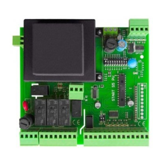
• Single-phase control unit for one motor 230 / 400 opto-isolated
• For rapid doors or roll up doors
• Automatic time counter, 4 functions, bush function.
START-S5PV
- 1 -
0 Vac
- 2 -
230 Vac
- 3 -
400 Vac
Opening contactor
Closing contactor
Common contactor
Brake/Light COM
Brake/Light OLS NA
Brake/Light CLS NC
Lamp
Lamp
Test
Test
24 Vac
24 Vac
Common
Photo-beam close
Stop
Services (input for safety edge)
Pedestrian
Start
Common
Common
Common
Antenna
Opening limit-switch
Closing limit switch
Input for opening control
Input for closing control
Light
Light
Man present open
Man present close
- 4 -
- 5 -
- 6 -
- 7 -
- 8 -
- 9 -
-10-
-11-
-12-
-13-
-14-
-15-
-16-
-17-
-18-
-19-
-20-
-21-
-22-
N.O.
N.O.
-23-
-24-
-24-
N.C.
-26-
N.C.
-27-
N.O.
-28-
N.O.
-29-
-30-
-31-
-32-
-33-
4
5
6
Passive brake: In case of lack of tension the brake works
BRAKE
DIP 1 B - OFF (Par.no 4.4)
Output for lamp with
or without card
(DIP7)
N.C.
Manual for the installer
Opening
remote-control
switch
4
5
6
6
With this connection the
"man present" is always
activated
32
N.O.
This connection shows that
the "man present" is activated
with STOP function
32
N.O.
N.O.
16
230/400 Vac
Closing
remote-control
switch
33
34
N.O.
33
34
17
18
Advertisement
Table of Contents

Related Manuals for nologo START-S5PV


Summary of Contents for nologo START-S5PV
- Page 1 • Single-phase control unit for one motor 230 / 400 opto-isolated • For rapid doors or roll up doors • Automatic time counter, 4 functions, bush function. START-S5PV 230/400 Vac Manual for the installer - 1 - 0 Vac Opening...
- Page 3 START-S5PV Technical manual Foreword Index Introduction This manual provides all the specific information you need to fa- miliarize yourself with and correctly operate your unit. Safety precautions Read it very carefully when you purchase the instrument and con- Symbols and warning sult it whenever you have doubts regarding use and before per- forming any maintenance operations.
- Page 4 START-S5PV Technical manual Introduction Safety precautions Using the unit improperly and performing repairs or modifications personally will void the warranty. The producer declines any responsibility for damages due to inappropriate use of the product and due to any use other than the use the product was designed for. The producer declines any responsibility for consequential damages except civil liability for the products. Remember that systems for automatic gates and doors must be installed by highly qualifi ed technicians only and in full compliance with current law. Before starting installation, check that the mechanical consistency and sturdiness of the gate or door, check that the mechanical stops are suitable to stop the movement of the gate or door even if the electrical limit switches should fail or during manual operations.
- Page 5 Photo Rx Cable 3x0,5 o 0,75 mm Type of installation START-S5PV control unit is designed for roll-up doors or rapid doors. Connections Notes To guarantee operator safety and to prevent damaging the components, never make connections or insert wireless receiver boards while the control unit is powered. Power the control unit through a 3 x 1.5 mm cable. If the distance between the control unit and the ground system connection is more than 30 m, a ground plate must be installed in proximity to the control unit.
- Page 6 START-S5PV Technical manual Installation of the control unit Description of the electrical connections 0 Vac 0 Vac 230 Vac 230 Vca 50 Hz power supply 400 Vac 400 Vca 50 Hz power supply Opening contactor Output for OPEN contactor Closing contactor...
- Page 7 START-S5PV Technical manual Scheme of the control board When the control unit is powered, the lights LED are turned on when the common contact is closed. LED TEST - RED It indicates if the control uniti s working properly. It should fl ash...
- Page 8 START-S5PV Technical manual Connection of the TENSION Connection of the TENSION. It can be two ways of powering the control unit: 230 Vac 400 Vac The power supply of the control unit should be protected from a magnet-switch or from a couple of 5A fuses.
- Page 9 START-S5PV Technical manual Description of securities The control unit dispose of inputs for CLOSING PHOTO-BEAM and STOP. The first contact is activated only when the motor is closing or is in pause time; if this safety intervene while the motor is closing, the control unit stops and invert the motor until a new completely opening, while if the intervention is during the pause time it recharge the pause time and it doesn’t recluse.
- Page 10 START-S5PV Technical manual 2.10 Connection of STOP devices The connection of safety devices can be down If the input STOP with every button or a NC contact. is not used make a link. (16-18) BUTTON: it stops temporary the control unit until a new function.
- Page 11 START-S5PV Technical manual Functions and adjustment The control unit dispose of DIP A which can used to activate different functions to make the installation suitable to the customer’s requirements and for more safety. Set up of the START control and PARTIAL OPENING of the DIP A Each control the motor invert.
- Page 12 START-S5PV Technical manual Resume of the functions with other DIP A micro-switches The control board dispose of several micro-switches DIP A for different function according the customer requirements and for a safe installation: Working time Working time memorization 5-ON memorization with START and PARTIAL OPENING.
- Page 13 START-S5PV Technical manual Installation of the plug-in receiver and managing of the REMOTE CONTROL To manage the remote controls, the control unit should have a receiver. The control unit can manage different type of codes, the fi rst memorized code will determine the type of code, consequently it cannot be memorized different codes from the fi rst.
- Page 14 START-S5PV Technical manual Turn on and program of the control unit When the control uniti s turned on, if everything has been well connected, the gree l.e.d. TEST should flash while STOP, FOTO, FCA, FCC e EDGE, SHOULD BE LIT ON (if the gate is close OLS is turned off). L.E.D START and PED have to be turned off. When the control unit is turned on and the motor starts opening, it means that the control unit has been previously turned off (tension cut off).
- Page 15 START-S5PV Technical manual Working time memorization with PARTIAL OPENING control The PARTIAL OPENING control can be used for a partial opening of the door and permit the passage of people or small vehicles just to avoid the complete opening of the gate.
- Page 16 START-S5PV Technical manual Note -16-...
- Page 17 START-S5PV Technical manual Declaration of CE conformity (according to EC Directive 98/37/EC, Attachment II, part B) Company: EB TECHNOLOGY SRL Address: Corso Sempione 172/5 The undersigned , 21052 Busto Arsizio VA Italy Ernestino Bandera Administrator Product’s name: START-S5PV DECLARES THAT:...
- Page 18 START-S5PV Technical manual DICHIARAZIONE DI CONFORMITA’ DECLARATION OF CONFORMITY DÉCLARATION DE CONFORMITÉ Il sottoscritto, rappresentante il seguente cos- The undersigned, representative of the fol- Le soussigné, représentant du constructeur truttore, dichiara che l’apparecchio denomi- lowing manifacturer, hereby certifies that the...
- Page 20 EB TECHNOLOGY S.r.l. NOLOGO S.r.l. Corso Sempione 172/5, via Cesare Cantù 26, 21052 Busto Arsizio VA Italia 20020 Villa Cortese MI Italia tel. +39 0331.683310 tel. +39 0331.430457 fax.+39 0331.684423 fax.+39 0331.432496 posta@ebtechnology.it info@nologo.info www.ebtechnology.it www.nologo.info...
Need help?
Do you have a question about the START-S5PV and is the answer not in the manual?
Questions and answers
NECESITO 2 TARJETAS START S5PV EN MEXICO LAS PUEDO CONSEGUIR. HAY DISTRIBUIDOR
@MARIO ALBERTO MUÑOZ