Panasonic EP30006 Service Manual
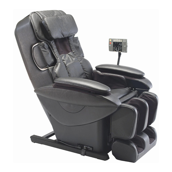
Massage lounger
Hide thumbs
Also See for EP30006:
- Service manual (72 pages) ,
- Operating instructions manual (52 pages) ,
- Instrucciones de uso (51 pages)

Related Manuals for Panasonic EP30006


Summary of Contents for Panasonic EP30006
- Page 1 EP30006 ORDER NO.HPD0706U16C1 MASSAGE LOUNGER EP30006 SPECIFICATIONS ©2007 Matsushita Electric Works, Ltd. All rights reserved. Unauthorized copying and distribution is a violation of law. - 1 -...
-
Page 2: Table Of Contents
EP30006 ORDER NO.HPD0706U16C1 CONTENTS Page 1 COMPONENTS IDENTIFICATION…………………………………………………………………………………………………………………………3 2 TURNING ON THE POWER………………………………………………………………………………………………………………………………7 3 REQUIRED TOOLS…………………………………………………………………………………………………………………………………………8 4 ADJUSTMENT OF PRESSURE SENSOR…………………………………………………………………………………………………………………9 5 OPERATIONS OF ELECTROMAGNETIC VALVES AND AIR BAGS………………………………………………………………………………10 6 DISPLAY METHOD OF MASSAGE BLOCK TOTAL USE TIME………………………………………………………………………………………11 7 DISPLAY METHOD OF EACH OPERATION USE TIME………………………………………………………………………………………………12 8 METHOD OF PACKAGING POSITION SET-UP…………………………………………………………………………………………………………12... -
Page 3: Components Identification
EP30006 ORDER NO.HPD0706U16C1 1. COMPONENTS IDENTIFICATION 1.1 MASSAGE LOUNGER - 3 -... - Page 4 EP30006 ORDER NO.HPD0706U16C1 - 4 -...
- Page 5 EP30006 ORDER NO.HPD0706U16C1 1.2 CONTROLLER - 5 -...
- Page 6 EP30006 ORDER NO.HPD0706U16C1 - 6 -...
-
Page 7: Turning On The Power
EP30006 ORDER NO.HPD0706U16C1 2. TURNING ON THE POWER Plug the power plug into the power socket. Turn the lock switch to the open position. Turn on the power switch on the back of the unit. ・ When the operating lock switch is pointing toward ‘lock’, the power switch cannot be moved to the ‘on’ position. -
Page 8: Required Tools
EP30006 ORDER NO.HPD0706U16C1 3. REQUIRED TOOLS - 8 -... -
Page 9: Adjustment Of Pressure Sensor
EP30006 ORDER NO.HPD0706U16C1 4. ADJUSTMENT OF PRESSURE SENSOR The adjustment of the Pressure sensor is necessary every time after the Main PCB or Massage mechanism block are replaced or repaired disassembled & reassembled. First, keep the Massage mechanism block unloaded without pressure and move it upward halfway. -
Page 10: Operations Of Electromagnetic Valves And Air Bags
EP30006 ORDER NO.HPD0706U16C1 5. OPERATIONS OF ELECTROMAGNETIC VALVES AND AIR BAGS Air massage operates with one Pump unit, nine 3-way electromagnetic valves, an Switch electromagnetic valve. Air massage operates with the Pump and the Electromagnetic valve. The Pump and all the Electromagnetic valves are OFF when the operation stops. -
Page 11: Display Method Of Massage Block Total Use Time
EP30006 ORDER NO.HPD0706U16C1 6. DISPLAY METHOD OF MASSAGE BLOCK TOTAL USE TIME Insert the Power plug into the power source and turn on the switch of the Power source switch block. While pushing the buttons of Ⅲ and Ⅳ, continue to push the On/off button for more than approximately three seconds. -
Page 12: Display Method Of Each Operation Use Time
EP30006 ORDER NO.HPD0706U16C1 7. DISPLAY METHOD OF EACH OPERATION USE TIME While in the display method of Massage block total use time, push the button of START as many as you like based on what accumulative operation use time you want to know. -
Page 13: Method Of Massage Mechanism Block Installation Mode Set-Up (Manual Set-Up)
EP30006 ORDER NO.HPD0706U16C1 9. METHOD OF MASSAGE MECHANISM BLOCK INSTALLATION MODE SET-UP (MANUAL SET-UP) It is necessary to adjust the Massage mechanism block to Manual mode when installing or removing the Massage mechanism block or adjusting the Up/down position as follows: Insert the Power plug into the power source and turn on the switch of the Power source switch block. -
Page 14: Disassembly
EP30006 ORDER NO.HPD0706U16C1 10. DISASSEMBLY 10.1. Removing the Rear cover Remove two screws and two push-turn rivets, and pull off the Rear cover top. Remove two brushclips from the Rear cover bottom, and pull off the Rear cover bottom. 10.2. Removing the Massage mechanism block Move the Massage mechanism block to the bottom pushing the high/low adjustment button. - Page 15 EP30006 ORDER NO.HPD0706U16C1 Unscrew a screw on the Ground wire and disconnect two Connectors. Remove the Connecting cord for power source from the Massage block cover clip. Unscrew four screws each on both sides and remove the Rail piece sets.
- Page 16 EP30006 ORDER NO.HPD0706U16C1 Caution when handling the Massage mechanism block Be sure to handle the Massage mechanism block carefully so that the PCB of the Pressure sensor is not pushed to the desk or given extra pressure when putting the Massage mechanism block, which could lead to the cracks of the PCB.
- Page 17 EP30006 ORDER NO.HPD0706U16C1 Remove the Hose connected to the Armrest. Lift the Armrest and remove it. Execute the same procedure on the opposite side. 10.4. Removing the Covers Proceed the all the procedures of 10.3. Removing the Controller stand and the Armrest.
- Page 18 EP30006 ORDER NO.HPD0706U16C1 Remove the B and pull out the Hose connected to the B. Unscrew two screws on the C. Lift the C to remove it. Unscrew ten Push-turn rivets, and remove the Lift protection sheet. - 18 -...
- Page 19 EP30006 ORDER NO.HPD0706U16C1 Unscrew nine Push-turn rivets on the Under cover right/left. Remove the Under cover right/left. *Remove the Power source switch box before removing the Under cover left. Caution when installing When installing the Under covers, be sure to check whether the Air hoses are hooked or bent and also the Ottoman block moves smoothly.
- Page 20 EP30006 ORDER NO.HPD0706U16C1 Unscrew two screws and remove the D. Remove the Rod holder from the Under cover top/right. Remove seven Hoses from the Under box top/left, and remove the Under box top/left. *When installing Hoses, be careful of the arrangement of the Hoses.
- Page 21 EP30006 ORDER NO.HPD0706U16C1 10.6. Removing the Lift unit 10.6.1. Removing the Ottoman lift unit Proceed all the all the procedures of 10.2. Removing the Massage mechanism block. * The work will be easy and secure if the Massage mechanism block is completely moved down.
- Page 22 EP30006 ORDER NO.HPD0706U16C1 10.6.2. Removing the Reclining lift unit Proceed all the all the procedures of 10.2. Removing the Massage mechanism block. * The work will be easy and secure if the Massage mechanism block is completely moved down. Proceed all the procedures of 10.4. Removing the Covers.
- Page 23 EP30006 ORDER NO.HPD0706U16C1 10.7. Removing the Seat Proceed all the procedures of 10.1. Removing the Rear cover, 10.3.2. Removing the Armrest, and 10.4. Removing the Covers. Unscrew three Screw. Unhook the Hooks at both sides. Pull off the Seat air hose.
- Page 24 EP30006 ORDER NO.HPD0706U16C1 Unscrew two Pushturn rivets eacht at both sides. Caution in installing When installing the Pushturn rivets or Hooks, pull the Ottoman lever and make the Ottoman extended fully so that Air hoses are not hooked. Unzip the Zippers on the reverse side.
- Page 25 EP30006 ORDER NO.HPD0706U16C1 Unscrew three screws each at both sides and remove the foot covers at both sides. Pull off the Pin and the Snap pin, and remove G (both sides). 10.9. Removing the Ottoman 10.9.1. Removing the Ottoman Proceed all the procedures of 10.4. Removing the Covers.
- Page 26 EP30006 ORDER NO.HPD0706U16C1 Pull out five Hoses and remove them from the Rod holder, which passes Hoses to the Under pipe. The work will be easy if you do before the Ottoman is removed. Caution when installing Be sure to check if the swell parts of the Rod holder faces the Seat.
- Page 27 EP30006 ORDER NO.HPD0706U16C1 Remove the Hinge pin B, Flat washer, U nut, then you can remove the Ottoman. 10.9.2. Disassembling the Ottoman Proceed all the procedures of 10.9.1. Removing the Ottoman. Remove the Spring. If it is difficult, push down the middle of the Spring and pull up the tips of the Spring with pliers.
- Page 28 EP30006 ORDER NO.HPD0706U16C1 Unscrew four screws, and remove J. Be careful not to lose the Washer, which is installed at one side. Unzip two zippers. Pull out the Hose from the hole of the cloth, remove a Spring and a Hose, and you can remove the Air Ottoman cloth.
- Page 29 EP30006 ORDER NO.HPD0706U16C1 Unscrew five screws, and remove K. Pull off the Snap pin, and pull off the Pins at both sides, and the upper and lower Ottoman break apart. Remove Air bags as the figure. - 29 -...
- Page 30 EP30006 ORDER NO.HPD0706U16C1 Caution in installing Arrange Hoses as figures and bundle them. Caution in installing Be careful of the directions of the Sole shiatsu sheets. - 30 -...
- Page 31 EP30006 ORDER NO.HPD0706U16C1 10.10. Removing the Headrest, Back cushion, and Massage wheel cover 10.10.1 Removing the Headrest Remove the Headrest. 10.10.2 Removing the Back cushion Unzip the zippers, and remove the Back cushion. 10.10.3. Removing the Massage wheel cover * You can work even with the Massage mechanism block installed.
- Page 32 EP30006 ORDER NO.HPD0706U16C1 10.10.4. Removing the Outside shoulder right/left Proceed the procedures of 10.10.3 Removing the Massage wheel cover. Cut the Insulated ties at both sides. Pull out the Upper parts of Air hose. Unscrew five screws, and pull off the Outside shoulder unit forward to remove it.
- Page 33 EP30006 ORDER NO.HPD0706U16C1 10.11. Removing the Rear frame Proceed the procedures of 10.4. Removing the Covers, and 10.10.3. Removing the Massage wheel cover. Pull off three Pins. Be careful of the Rear frame, which may fall down after Pins are taken off.
- Page 34 EP30006 ORDER NO.HPD0706U16C1 10.12. MASSAGER UP/DOWN SENSOR GEAR ADJUSTMENT METHOD When the massager is removed from the chair, the position of the up/down sensor gear changes, resulting in a change of the up/down stop position. When installing the massager on the back frame, be sure to adjust the position with the up/down detection gear.
- Page 35 EP30006 ORDER NO.HPD0706U16C1 10.13. TIPS IN INSTALLING THE CONNECTING CORD FOR POWER SOURCE Move the Massage mechanism block to the highest position. * After installing each Connecting wires, be sure to move the Massage mechanism block up and down pushing the buttons on the Controller so as to check whether each Connecting cords do not touch Belts or the Rear cover fixing plate or are not hooked on the Up/down pinions on both sides.
- Page 36 EP30006 ORDER NO.HPD0706U16C1 10.14. ALLOCATION OF EACH LEAD WIRE OF MASSAGE MECHANISM Allocate the Main PCB, each Motors, each Sensors, and the other parts and bind the Insulated ties as the figure. - 36 -...
- Page 37 EP30006 ORDER NO.HPD0706U16C1 10.15. DISASSEMBLY AND ASSEMBLY OF MASSAGE MECHANISM BLOCK 10.15.1. DISASSEMBLY OF AIR UNIT Remove the Massage mechanism block from the Rear frame. Unscrew four Screws, and remove the PCB cover. Unscrew two Screws, two Brushclips, and four Install rubbers on the Air unit.
- Page 38 EP30006 ORDER NO.HPD0706U16C1 10.15.2. Removing the Up/Down sensor Disconnect the Connector. Cut two Insulated ties. Unscrew two Screws, which screw the Up/down gear box B and the Up/down sensor install plate, and remove the Up/down sensor. Caution in assembly Be sure to make the foot of the Sensor install plate fit into the ditch of the Up/down gear box B when installing the Up/down sensor.
- Page 39 EP30006 ORDER NO.HPD0706U16C1 10.15.3. Removing the Intensity sensor Disconnect the Connectors on the Main PCB. Cut two Insulated ties. Unscrew one Screw. Caution in assembly - Put the swell parts of the Massage mechanism block frame to the hollow parts of the Intensity sensor. (Otherwise, it may lead to the overrun in the direction of stronger.)
- Page 40 EP30006 ORDER NO.HPD0706U16C1 10.15.4. Removing the Width sensor Disconnect all the Connectors on the Main PCB. Cut the Insulated ties bundling the Lead wires. Unscrew four Screws on the Main PCB install plate. Cut three Insulated ties on the Width sensor install plate.
- Page 41 EP30006 ORDER NO.HPD0706U16C1 10.15.5. Removing the Width motor Disconnect the Connector (CN501) on the Main PCB. Cut the Insulated ties bundling Lead wires. Remove the Width belt. Unscrew four Screws on the Width motor. 10.15.6. Removing the Pinching air bag Remove the Massage mechanism block from the Rear frame.
- Page 42 EP30006 ORDER NO.HPD0706U16C1 10.15.8. Removing the Float air bag Remove the Massage mechanism block from the Rear frame. Remove the PCB install plate. Remove the Pin. Remove the Rivet. Unscrew the Screw. Move the Float air bag in the direction of arrows, and remove it from the hollow parts of the Float air bag.
- Page 43 EP30006 ORDER NO.HPD0706U16C1 10.15.10. Removing the Up/down gear block *You cannot replace the Up/down shaft or Up/down motor unless you disassemble the Up/down gear block. *Proceed the procedures of 1-4 of 10.15.5. Removing the Width sensor. Remove the Massage mechanism block from the Rear frame.
-
Page 44: Actual Wiring Diagram
EP30006 ORDER NO.HPD0706U16C1 11. ACTUAL WIRING DIAGRAM 11.1. HOSE ALLOCATION - 44 -... - Page 45 EP30006 ORDER NO.HPD0706U16C1 11.2. WIRING DIAGRAM OF MAIN PCB AND SUB PCB - 45 -...
- Page 46 EP30006 ORDER NO.HPD0706U16C1 11.3. HOSE ALLOCATION OF AIR OTTOMAN - 46 -...
-
Page 47: Phenomena Caused By The Sensor Malfunction Or Lock Protection Operation
EP30006 ORDER NO.HPD0706U16C1 PHENOMENA CAUSED BY THE SENSOR MALFUNCTION OR LOCK PROTECTION OPERATION 12.1. Phenomena caused by the sensor malfunction - 47 -... - Page 48 EP30006 ORDER NO.HPD0706U16C1 12.2. Phenomena caused by the Reclining lift (Ottoman lift) sensor 12.3. Phenomena in the Lock protection movement (abnormal detection by the overloading) by the Reclining lift motor (Ottoman lift motor) - 48 -...
-
Page 49: Checking
EP30006 ORDER NO.HPD0706U16C1 13. CHECKING - 49 -... - Page 50 EP30006 ORDER NO.HPD0706U16C1 - 50 -...
- Page 51 EP30006 ORDER NO.HPD0706U16C1 - 51 -...
- Page 52 EP30006 ORDER NO.HPD0706U16C1 - 52 -...
- Page 53 EP30006 ORDER NO.HPD0706U16C1 - 53 -...
- Page 54 EP30006 ORDER NO.HPD0706U16C1 13.2. CHECKING THE AIR BAGS You can check the air leakage by this inspection. Remove the Under covers. Connect the Air inspection tool (WEP000S8908) and the Special hose (WEP000K8917) to each Hoses from the Under box. *Connect to the Hose that you inspect.
- Page 55 EP30006 ORDER NO.HPD0706U16C1 *Requested pressure values are as follows: - 55 -...
- Page 56 EP30006 ORDER NO.HPD0706U16C1 13.3. CHECKING THE ELECTROMAGNETIC VALVES You can check the Electromagnetic valves.Proceed all the procedures of 10.4. Removing Covers, and 10.5. Removing Under box and Under box cover. Remove the Hose, which issues air, and check if the operation voltage of the Electromagnetic valve is as follows: The output voltage of the Connector White (CN203) on the Sub PCB is approx.
-
Page 57: Grease
EP30006 ORDER NO.HPD0706U16C1 14. GREASE - 57 -... - Page 58 EP30006 ORDER NO.HPD0706U16C1 - 58 -...
- Page 59 EP30006 ORDER NO.HPD0706U16C1 - 59 -...
-
Page 60: Exploded View
EP30006 ORDER NO.HPD0706U16C1 15. EXPLODED VIEW - 60 -... - Page 61 EP30006 ORDER NO.HPD0706U16C1 - 61 -...
- Page 62 EP30006 ORDER NO.HPD0706U16C1 - 62 -...
- Page 63 EP30006 ORDER NO.HPD0706U16C1 - 63 -...
- Page 64 EP30006 ORDER NO.HPD0706U16C1 - 64 -...
- Page 65 EP30006 ORDER NO.HPD0706U16C1 - 65 -...
-
Page 66: Replacement Parts List
EP30006 ORDER NO.HPD0706U16C1 16. REPLACEMENT PARTS LIST Ref.No. Part No. Part Name & Description Remarks Per Unit WEP3530L0087 REAR FRAME WEP3530L0007 SIDE HINGE FITTING RIGHT WEP3530L0017 SIDE HINGE FITTING LEFT WEP3530L6717 SCREW WEP3200L0887 RESING BUSHING WEP3530L0267 REAER COVER FXING PLATE... - Page 67 EP30006 ORDER NO.HPD0706U16C1 Ref.No. Part No. Part Name & Description Remarks Per Unit WEP3530L0637 SOLE SHIATSU SHEET LEFT WEP3200L0467 ANCHOR CLIP WEP3530L0687 HOSE 2 ROW LEG BLACK WEP3530L0887 HOSE 1 ROW LEG WEP3530L0697 HOSE 2 ROW BROWN WEP3530L0677 CONNECTION HOSE...
- Page 68 EP30006 ORDER NO.HPD0706U16C1 Ref.No. Part No. Part Name & Description Remarks Per Unit WEP3200L0267 UNDER BOX TOP RIGHT WEP3210L0257 UNDER BOX TOP LEFT WEP3530S4458 CONTROLLER WEP3530K7187 CONTROLLER STAND WEP3515K7197 CONTROLLER CORD INSTALL HOLDER WEP3530L7937 INSTALL SCREWS WEP3530L2907 CONNECTING CORD FOR ELECTROMAGNETIC VAVLE...
- Page 69 EP30006 ORDER NO.HPD0706U16C1 Ref.No. Part No. Part Name & Description Remarks Per Unit WEP3530K3127 SHOULDER OUTSIDE SHIATSU SHEET WEP3530K3178 REAR COVER TOP WEP3530K3168 REAR COVER BOTTOM WEP3510K0997 SCREW-RIVET WEP2110K0447 PUSH-TURN RIVET WEP3530K3688 SEAT K WEP3530T3688 SEAT T WEP3510L1327 SLIDE COVER PLATE BLOCK...
- Page 70 EP30006 ORDER NO.HPD0706U16C1 Ref.No. Part No. Part Name & Description Remarks Per Unit WEP3530L2188 UP/DOWN SENSOR WEP3510L1397 UP/DOWN SENSOR GEAR WEP3200L1847 UP/DOWN SENSOR INSTALL PLATE WEP590L6017 SCREW WEP3510L0227 UP/DOWN DRIVING INSTALL PLATE WEP3530L1038 WIDTH MOTOR BLOCK WEP3530L2147 WIDTH MOTOR VELOCITY SENSOR...
- Page 71 EP30006 ORDER NO.HPD0706U16C1 Ref.No. Part No. Part Name & Description Remarks Per Unit WEP3530L0197 HOSE GUIDE B WEP3510S9057 SCREW WEP3510L0137 T SHAPED JOINT 2 WEP3510L0167 TAPPING PLATE PULLING SPRING WEP3510L0477 INTENSITY SENSOR PLATE WEP3510L0507 INTENSITY SENSOR PLATE GREASE COVER WEP3510L0497...
- Page 72 ORDER NO. HPD1202U13PE Model No. EP30006 Please revise the original parts list in the Service Manual to conform to the change(s) shown herein. If new part numbers are shown, be sure to use them when ordering parts. Reason for Change *The circled item indicates the reason.
- Page 73 ORDER NO. HPD1104C01PE Model No. EP30006 Please revise the original parts list in the Service Manual (Order No.:HPD0709C21C1) and the Supplement manual (Order No.:HPD0809C09S1) to conform to the change(s) shown herein. If new part numbers are shown, be sure to use them when ordering parts.
- Page 74 ORDER NO. HPD1303U01PE Model No. EP30006 Please revise the original parts list in the Service Manual (ORDER NO. HPD0709C21C1)to conform to the change(s) shown herein. If new part numbers are shown, be sure to use them when ordering parts. Reason for Change *The circled item indicates the reason.
- Page 75 ORDER NO. HPD0906U10P1 Model No. EP30006/EP30005/EP30004 EP30003 Please revise the original parts list in the Service Manual to conform to the change(s) shown herein. If new part numbers are shown, be sure to use them when ordering parts. Reason for Change *The circled item indicates the reason.
- Page 76 ORDER NO. HPD0906U07P1 Model No. EP30006/EP30005/EP30004 EP30003 Please revise the original parts list in the Service Manual to conform to the change(s) shown herein. If new part numbers are shown, be sure to use them when ordering parts. Reason for Change *The circled item indicates the reason.
Need help?
Do you have a question about the EP30006 and is the answer not in the manual?
Questions and answers