Table of Contents
Advertisement
Quick Links
Advertisement
Table of Contents

Subscribe to Our Youtube Channel
Summary of Contents for LG LG M1C Series
-
Page 2: Table Of Contents
Contents 1. Before installation ............3 2. -
Page 3: Before Installation
1. Before installation Please carefully read this manual before installation. • Solar module installation should be • Do not drop the solar module and cause an performed by an authorized excessive load on solar module installer for the safety and mainte- nance of the system. -
Page 4: Handling Safety
• Do not locate the solar module horizontally, as this may cause dirt or white efflorescence (glass deformation) • Do not cover the water drain hole of the frame. Doing so causes the risk of frost damage when the frame is filled with water. - Handling Safety •... -
Page 5: Component
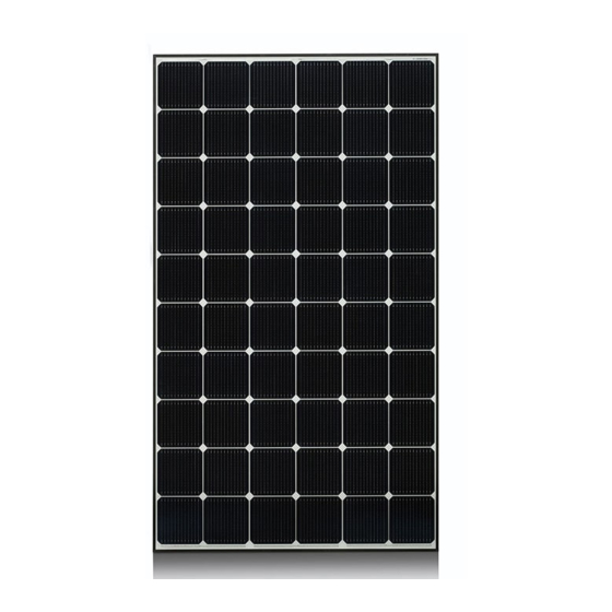
3. Component - Front Type A Type B Glass Solar Cell (Mono) Glass Solar Cell (Poly) - Back Junction Box Backsheet Frame Page 5... -
Page 6: Electrical Installation
Shock hazard shall be applied near the means of connection to the modules. - General Wiring LG Electronics recommends that all wiring be double insulated with a minimum rating of 90°C (194°F). All wiring should use a flexible copper (Cu) conductor. -
Page 7: Parallel Connection
- PARALLEL for more voltage - 5. Mechanical Installation - Module Mounting The LG Electronics (LGE) Limited Warranty for solar modules is contingent upon modules being mount- ed in accordance with the requirements described in this section. * Application class A - Site Consideration LGE solar modules should be mounted in a location that meets the following requirements. -
Page 8: Mounting Configurations
Design Strength LGE solar modules are designed to meet a maximum positive or upward, e.g. wind and negative or downward, e.g. static, load of 5400 Pa (1Pascal: 540kg/m ) when mounted in one of the mounting con- figurations specified in Section 2.2. When mounting solar modules in snow prone or high wind environments, special care should be taken to mount the solar modules in a manner that provides sufficient design strength while meeting the local code requirements. - Page 9 Frame Hole(A) <Figure 1> Frame Holes Secure the solar module to the structure using the factory mounting holes. Four M6 stainless steel bolts, four nuts, four spring washers, and eight plain washers are recommended per solar module. Refer to Figure 1 for the solar module dimensions and mounting hole locations. The module may be fastened to a support using the bolt holes in the bottom of the frame at location ‘A’...
- Page 10 Mounting using clips on the long edge of the module The module may be mounted using clips (cramps) designed for solar modules, as shown in Figures 2 and 3. Note that the clip positions are maintained-the clip centerlines must be between 7” and 16” from the end of the module.
-
Page 11: Mechanical Characteristics (All Types)
- Mechanical characteristics (All types) Description LGxxxM1C & LGxxxP1C Length 1649mm Width 993mm Depth 42mm Weight 19kg Drain holes 4 places 23.4 2- 4.3 Grounding holes 4 places Junction Box Detail A 11x6.5 Scale 1:5 Mounting slots 8 places Detail B Scale 1:5 Detail C 12x5... -
Page 12: Product Specification
6. Product Specification - Mono-crystalline Standard Test Condition (STC): Irradiation 1,000W/m , Cell temp. 25°C, 1.5AM Model LG230M1C LG235M1C LG240M1C 36.6V 36.8V 36.9V 29.5V 29.6V 29.7V 7.81A 7.94A 8.10A 8.37A 8.49A 8.58A Pmax 230W 235W 240W Output Tolerance +3% / -0% +3% / -0% +3% / -0% Maximum System Voltage... -
Page 13: Poly-Crystalline
- Poly-crystalline Standard Test Condition (STC): Irradiation 1,000W/m , Cell temp. 25°C, 1.5AM Model LG220P1C LG225P1C LG230P1C 36.1V 36.3V 36.4V 28.9V 29.0V 29.1V 7.62A 7.76A 7.91A 8.21A 8.30A 8.39A Pmax 220W 225W 230W Output Tolerance +3% / -0% +3% / -0% +3% / -0% Maximum System Voltage 1,000V... -
Page 14: Ground Method
7. Ground method To prevent electric shock or fire, an earth must be done on the frames of solar modules. Bolt Plain Washer Toothed Lock Washer Grounding Wire Screw Washer <Figure 5> Grounding hardware Dimension & material Remark Hexagon nut & bolt M4 stainless The length of the bolt: 15 mm Plain washer... - Page 15 Memo Page 15...


Need help?
Do you have a question about the LG M1C Series and is the answer not in the manual?
Questions and answers