
Related Manuals for Matrix MPS-6003LP-3


Summary of Contents for Matrix MPS-6003LP-3
- Page 1 USER MANUAL Triple Output Programmable DC Power Supply Model MPS-6003LP-3 and MPS- 3006LP-3 © Copyright belongs to Matrix USER MANUAL...
-
Page 2: Table Of Contents
CHAPTER 1 INSPECTION AND INSTALLATION....................... 6 1.1 I ................................6 NSPECTION 1.2 D ................................. 7 IMENSION CHAPTER 2 QUICK REFERENCE..........................9 2.1 T ....................9 HE FRONT PANEL AND REAR PANEL DESCRIPTION 2.1.1 Front panel ..............................9 2.1.2 The Rear Panel ............................... 9 2.2 P ............................ - Page 3 About your safety Please do not install replacement parts in the instrument, or perform any unauthorized modification. Please send the instrument to our company's maintenance department for maintenance, to ensure its security features. Please refer to the manual for specific information warning or precautions to avoid personal injury or equipment damage.
- Page 4 Warranty Service For the warranty service or repair the product, the product must be returned to the designated maintenance units. Return the product to us for warranty service, the customer should pre-pay the one-way Freight to the maintenance department, and our company is responsible for the return shipping cost.
- Page 5 MPS-XXXXLP-3 DC programmable power supply Introduction MPS-XXXXLP-3 triple output programmable DC power supply,the output voltage or current of each channel can be set from 0 to max rated value. The triple output power supply provides you with high-resolution, high accuracy and high stability, and supports over voltage, over temperature protection;...
-
Page 6: Chapter 1 Inspection And Installation
When you receive your AC source, inspect it for any obvious damage that may have occurred during shipment. If there is damage, notify the shipping carrier and the nearest Matrix Sales and Support Office immediately. 2. Accessories Make sure you receive the AC source and the following accessories at the same time, if any is missing, please contact your nearest support office. - Page 7 1.2 Dimension MPS-XXXXLP-3 power supply’s dimension: Dimension: 215mmW×90mmH×452.m12mmD (W:width H:height D:depth) * refer to the Dimension below: Front view for MPS- 6003LP-3/MPS-3006LP-3 Lateral view for MPS- 6003LP-3/MPS-3006LP-3 USER MANUAL...
-
Page 8: Chapter 2 Quick Reference
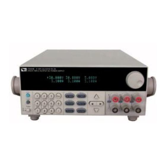
Chapter 2 Quick Reference 2.1 The front panel and rear panel description 2.1.1 Front panel VFD display Rotary knob Power switch, Local and Shift key Numeric keys and ESC escape key Function keys Up/Down/Left/Right keys Output terminal 2.1.2 The Rear Panel USER MANUAL... -
Page 9: Preliminary Checkout
Cooling window RS232 communication interface USB communication interface Remote measurement terminal 110V/220V AC power selection switch and Fuse 2.2 Preliminary Checkout The following steps help you verify that the power supply is ready for use. 2.2.1 Check the list of supplied items Verify that you have received the following items with your power supply, if anything is missing, contact your authorized supplier. -
Page 10: Checkout Procedure
too hot. Warning:To avoid any fire or electric shock, please ensure the AC input voltage fluctuation not exceed 10% of the working voltage range. Note:In some situation, use the mis-configured main voltage for the instrument may cause the main fuse blew. Note:If the power supply is used to charge a battery, please pay attention to the positive and negative polarity to avoid any damage. - Page 11 Picture 6 If calibration data read failure, the VFD display the tooltip information (about 2 s): Cal Lost Picture 7 If the factory calibration data loss, restoring default data, the VFD display the tooltip information (about 2 s): Fact Lost Picture 8 If the channel to send data loss, channel initialization failed, the VFD display the tooltip information (about 2 s):...
-
Page 12: If The Power Supply Does Not Turn On
3) Verify the correct power-line fuse is installed If the fuse was damaged, please see the table below to replace the fuse for your power supply Model Fuse (220V AC) Fuse (110V AC) MPS-6003LP-3 5A T250V 10A T250V 5A T250V 10A T250V MPS-3006LP-3... -
Page 13: How To Exchange The Fuse
2.2.6 How to exchange the fuse Open the small plastic cover below the power supply input socket on the back panel with a screwdriver, and you can see the fuse in it, please use the specifications in line fuse. Remove the power cord and then use a screwdriver to remove the fuse box. Use the same specification of fuse to replace the old one, install it to the fuse box and then insert. -
Page 14: Chapter 3 Specification
Chapter 3 Specification 3.1 Specification Parameters MPS-3006LP-3 Voltage 0~30V×2,0~5V×1 Rated voltage Current ( 0 °C - 40 °C) 0~6A×2,0~3A×1 ≤0.01%+3mV Voltage Load regulation ≤0.1%+3mA (%of output+offset) Current ≤0.01%+3mV Voltage Line regulation ≤0.1%+3mA Current (%of output+offset) Voltage Setting resolution Current Voltage Readback resolution Current Setting accuracy... - Page 15 Parameters MPS-6003LP-3 Voltage 0~60V×2,0~5V×1 Rated voltage Current 0~3A×2,0~3A×1 ( 0 °C - 40 °C) ≤0.01%+3mV Voltage Load regulation ≤0.01%+3mA Current (%of output+offset) ≤0.01%+3mV Voltage Line regulation ≤0.01%+3mA Current (%of output+offset) Voltage Setting resolution Current Voltage Readback resolution Current Setting accuracy ≤0.03%+10mV...
-
Page 16: Chapter 4 Front-Panel Operation
Chapter 4 Front-panel Operation So far we have covered the quick start chapter which briefly introduced the front panel operation and how to check basic voltage and current functionality. This chapter describes in detail how to operate the instrument manually via the front-panel keys. 4.1 Front-panel Operation Overview ... -
Page 17: Panel Description
Details about key buttons’ state: V-set When button is lit, means you can set voltage. I-set When button is lit, means in current setting mode. Recall When button is lit, means in recall mode When button keeps flickering, means in save mode and waiting for a number to be entered to specify the memory location. -
Page 18: Vfd Description
(Power) Used to power on/off the DC source Used to set the voltage or shift+V-set to set OVP value V-set /OVP I-set /Menu Used to set the current or shift+I-set to enter the menu operation. /Save Recall Save or recall different operating parameters in memory locations Switch the display between setting value and actual value Enter button to confirm the selection or Shift+Enter to lock the... - Page 19 VFD,and use the right/left key to change the setup, and up/down key to scroll through the Enter complete menu items. Press to enter the selected menu function.Press button to return to the previous menu.When the item keeps filickering indicates it is selected currently.
- Page 20 Group 2 GRP2 Group 3 GRP3 Group 4 GRP4 Command SCPI Version SCPI version select Select… MATRIX ITECH SCPI command Extended SCPI EXT1 command 1 Return Meter Auto Return to Auto return to meter state Meter State Function off The front panel display will change from setting to meter state Wait5Sec automatically after 5s.
-
Page 21: Panel Operation
Config Configuration Menu System Menu CH1 System Menu Maxvolt Maxvoltage Set MaxVolt=31.000V Out Timer State Set Outtimer Timer State Disable Enable Exit System Menu… MaxVolt MaxVoltage Set MaxVolt=31.000V Out Timer= Out Timer Set OutTimer Timer State Disable Enable Exit System Menu… MaxVolt MaxVoltage Set MaxVolt=6.000v... -
Page 22: Out On/Off
V-set I-set When button is lit, press (Local) key can switch between the three channels. 4.5.2 OUT ON/OFF Pressing button toggles the output state of all 3 channes of the power supply.If the On/Off output state is ON,press it,to turn the output state to OFF.While the output state is OFF,press and the power supply output will turn ON. -
Page 23: Current Operation
Note: When output in OFF mode and button is dark, rotary knob and up/down keys can’t be used to adjust voltage and current. If rotary knob is enabled, then adjusting it will real-time change the current output Enter setup without pressing to confirm. -
Page 24: Key Lock Set
the OVP value.After set successfully,when the actual voltage is higher than OVP value,then VFD will display “OVER VOLT”. 4.5.8 Key Lock Set (Shift) + Press On/Off (Lock) can lock the front panel keys and label “ ”will be lit on the lower left corner In key lock mode, all keys are disabled, except On/Off... - Page 25 Communication This item set the communication mode, optional communication interfaces are RS232, USB, PortSelect interface, BaudRate . RS232 Communication Set This item configures the baud rate for serial communication.Possible values are 4800,9600,19200,38400,57600,115200.When operating the power supply in remote mode,make sure that you configure idential baud rate settings for the power supply and the computer.
- Page 26 The max voltage you set should be within the range of 0V to the maximum rated voltage.You can edit this value using the keys or via numerical key pad followed by Enter .The default setting is the maximum rated voltage for each channel. Out Timer This item sets the output timer for channel 1 Channel 2.The range is 0.1~99999.9S.If you enable this function,and the output state of all channels is on,the timer will start counting down...
- Page 27 IT6300B user manual Track (sync output setting) This function configures the instrument for tracking operations of CH1 and CH2. Possible Button to confirm your set, and press ESC to quit the operation. Press button to confirm your In tracking mode,once the parameters of any one channel are changed,other channels will change proportionally.
- Page 28 , VFD will display power information; the information includes the following parts: Power Model /MPS-3006LP-3 Display the model of power supply: MPS-6003LP-3 Soft Version firmware version of power supply: Ver=1.XX-1.XX Power SN Display the serial number of the power supply: SN:XXXXXXXXXXXXXXXXXX...
- Page 29 IT6300B user manual degradation of regulaiton that would occur due to the voltage drop in the leads between the power supply and the load.By connecting the supply for remote voltage sensing,voltage is sensed at the load rather than at the supply’s output terminals.This will allow the supply to automatically compensate for the voltage drop in the load leads and improve regulation.
-
Page 30: Chapter 5 Communication With Pc
IT6300B user manual Chapter 5 Communication with PC MPS-XXXXLP-3 Standard configuration have three communication interface:RS232,USB, The user can choose any one to realize the communication with the computer. The following content can help you understanding how to through the computer control power supply output. - Page 31 RS - 232 plug pin Pin number Description Connectionless TXD, transmit data RXD, receive data Connectionless Connectionless Connectionless Connectionless Connectionless RS-232 troubleshooting If the RS - 232 connection has a problem, check the following aspects: The computer and power supply must be installed with the same baud rate, the same parity bit, the same data bit and the same flow control options.
- Page 32 Start Bit 8 Data Bits Parity=None Stop Bit USER MANUAL...
- Page 33 Frequently Asked Question 1. The conductor weight specifications The following form lists the AWG copper wire to withstand maximum current value maximum current value Note: AWG (American Wire Gage), that is X line (the mark is on conductor). The above works on temperature 30 ℃...
- Page 34 Support process If you have a problem, follow these steps: 1 Check the documentation that come with the product 2 Visit the MATRIX online service Web site is www.szmatrix.com ,Matrix is available to all Customers 3. Contact us via email sales@szmatrix.com...
Need help?
Do you have a question about the MPS-6003LP-3 and is the answer not in the manual?
Questions and answers