Table of Contents
Advertisement
Advertisement
Table of Contents

Related Manuals for claber Aquadue DUPLO 8410


Summary of Contents for claber Aquadue DUPLO 8410
- Page 1 Aquadue DUPLO VOLT ALKALINE 8410 8410...
-
Page 2: Table Of Contents
Table of contents Introduction ..................3 Features .....................3 Operating controls ................4 Operating tips ..................5 Battery installation ................6 Installation on faucet ................7 Display and keyboard .................8 Programming ................9-13 Setting the current time..............9 Setting watering programs ............9 Deleting programs ..............11 Weekly programming ...............12 Manual mode ...................14 Frequently asked questions ............15-16 Trouble shooting .................17-18... -
Page 3: Introduction
• Built-in stainless steel filter traps harmful contaminants. • All settings are retained for 10 minutes while battery is removed. • Quick-click connect couplings for fast and easy hose removal. • Rain Sensor accessory available (sold separately; Claber model 90915). -
Page 4: Operating Controls
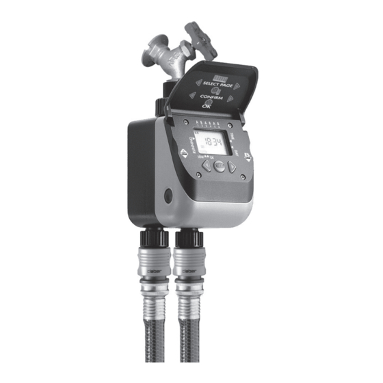
Operating controls Washable stainless steel filter 3/4” Female faucet connector with O-ring Flip-top Lid External ring-nut LCD display Valve body Right Arrow Unit opening buttons Programming (one on each side) 1/2” Female connector Enter Key Male Quick-Click Left Arrow connectors Programming Line B Line A... -
Page 5: Operating Tips
Operating tips • The two lines do not operate simultaneously to maintain water flow rate; programs open contecutively starting from program 1. • Weekly programming effects both lines. • Manual mode is preset for 15 minutes; shorter/longer time must be executed by hand. -
Page 6: Battery Installation
Battery installation 1. Press the two side buttons on the front panel then insert one new 9V Alkaline battery into the terminal. 2. Replace the battery back into the housing. 3.Battery power level indicator on the LCD display appears as: full BA T T E RY battery power,... -
Page 7: Installation On Faucet
Installation on faucet 1. Loosen external ring nut C. 2. Tighten 3/4” female connector A on faucet B. 3. Tighten external ring nut C to timer housing. Note: It is easier to program the timer be- fore attaching it to the faucet. •... -
Page 8: Display And Keyboard
Display and keyboard Daily programs Valve open indicator Manual mode Valve closed indicator Program identifier Programming Days of the week time lenght Battery power Blinking reminder level indicator for setting confir- mations RIGHT ARROW ENTER LEFT ARROW Moves forward Accesses the page Moves backward through the for modifying the... -
Page 9: Programming
Programming SETTING THE cURRENT TImE As soon as the battery is connected, the display will show the clock page in a few seconds. The two dots in the center blink when in operation. Setting time of day 1. Press (the icon will appear). - Page 10 Programming Setting opening time 1. Press pROGRAm 1 to display OpEN program identifier valve indicator 2. Press (the icon will appear). 3. Use arrow keys to increase decrease program time (holding down the arrow key will move through the clock faster) 4.
-
Page 11: Deleting Programs
Programming DELETING pROGRAmS 1. Use arrows keys to select the program you wish to delete, the display cLOSED must be in the option. 2. Press (the icon will appear). 3. Press first and while pressing this key, press until timer reads 00:00 cUSTOm pROGRAmmING EXAmpLE If you require single line programming see example below: STEP 1... -
Page 12: Weekly Programming
Programming Once programs are set (i.e. 1, 2, 3 and 5) they are visible by a numbered digital block on top of all pages. Number corresponding to the program currently in operation flashes until program is over. WEEkLy pROGRAmmING Weekly program effects both lines: the day selection will be set for all programs. - Page 13 Programming The correspondence between the numbers and the days of the week changes depending on the day in which you program therefore day 1 = the day in which you program the timer; use the table below as a reference. Example: if the day in which you are programming is Thursday (1) and you do not wish to run a watering cycle on Fridays and Mondays, eliminate day (2) and (5).
-
Page 14: Manual Mode
Manual mode Manual operation allows use of hose or faucet without disconnecting the timer and operates on each line without altering set programs. By default the manual mode is automatically preset for 15 minutes; shorter/ longer time must be executed by hand. 1. -
Page 15: Frequently Asked Questions
Frequently asked questions Why can’t unit water from both lines at the same time? Having both lines operating simultaneously water flow would be too low and the pressure not sufficient for proper operation of the hose end applications. can the programs be scheduled to operate on any specific week day? No, all programs must be set within a 24 hour window starting from midnight = 00:00. - Page 16 Frequently asked questions How do I determine the time in military hours? Use chart below as a reference: REGULAR TImE 01:00 02:00 03:00 04:00 05:00 06:00 07:00 08:00 09:00 10:00 11:00 noon 12:00 13:00 14:00 15:00 16:00 17:00 18:00 19:00 20:00 21:00 22:00 23:00 mILITARy TImE How much water is delivered per minute? Use chart below as a reference;...
-
Page 17: Trouble Shooting
Trouble shooting pROBLEm SOLUTION Verify the valves open/close when in manual mode (see “Man- ual mode” on page 14) Verify program(s) are set from the earliest to the latest time of day, based on military hours (see “Setting watering programs” The unit is not on page 9). -
Page 18: Routine Maintenance
Routine maintenance • Clean impurities inside and outside the unit. • Check that all wires are in good condi- tion. • Take apart solenoid valve case and clean dirty areas with water only. When reas- sembling, make sure that valve wires are in an upward position (see fig. -
Page 19: Warranty
Claber shall not be liable for damage on products manufactured by other companies when combined in use. Claber, at its own discretion, may require product or parts to be returned to the Warranty Department. All shipping charges and risks are incurred by customer. -
Page 20: Declaration Of Conformity
Declaration of conformity claber S.p.A. Via Pontebbana, 22 - 33080 - Fiume Veneto - Pordenone - Italy We hereby declare under our full responsibility that this product: 8410 - Aquadue Duplo conforms to European Directive 2004/108/CE With reference to the technical standards defined under EN61000-6-1:2007 (immunity) and EN61000-6-3:2007 (emissions).
Need help?
Do you have a question about the Aquadue DUPLO 8410 and is the answer not in the manual?
Questions and answers