Table of Contents
Advertisement
Quick Links
Advertisement
Table of Contents

Related Manuals for Trotec TTR 400


Summary of Contents for Trotec TTR 400
- Page 1 TTR 400 / TTR 400 D / TTR 500 D ORIGINAL INSTRUCTIONS DESICCANT DEHUMIDIFIER...
-
Page 2: Table Of Contents
Information marked with this symbol helps you to carry without supervision. out your tasks quickly and safely. Follow the manual Information marked with this symbol indicates that the instructions must be observed. desiccant dehumidifier TTR 400 / TTR 400 D / TTR 500 D... - Page 3 • The device must not be positioned directly beneath a wall socket. • The electrical connection must correspond to the specifications on the nameplate. Additionally, information regarding the electrical connection is provided in the technical annex. desiccant dehumidifier TTR 400 / TTR 400 D / TTR 500 D...
- Page 4 This behaviour is desired and necessary transport the device and perform simple maintenance activities to ensure operation with little supervision. (cleaning the housing, cleaning the fan). desiccant dehumidifier TTR 400 / TTR 400 D / TTR 500 D...
-
Page 5: Information About The Device
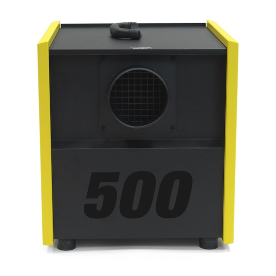
(depending on the configuration 3 to 30 rotations per hour). Via the sectors the desiccant wheel is simultaneously charged with the process and regeneration air so it can constantly absorb and release moisture. desiccant dehumidifier TTR 400 / TTR 400 D / TTR 500 D... - Page 6 Carrying handle Dry air outlet Feet Operating element Connection cable Air inlet grid with coarse particulate air filter Humid air outlet Air inlet grid with coarse particulate air filter desiccant dehumidifier TTR 400 / TTR 400 D / TTR 500 D...
-
Page 7: Transport And Installation
Trotec customer service. – The device can be connected in either recirculation or ventilation mode. A connection of the dry air to the room to be dehumidified must be established. desiccant dehumidifier TTR 400 / TTR 400 D / TTR 500 D... -
Page 8: Operation
Switch the device off by actuating the mains switch (17). heating current is indicated on the ammeter. This allows you to The integrated indicator light goes off. achieve very good dehumidification results at minimum energy input. desiccant dehumidifier TTR 400 / TTR 400 D / TTR 500 D... -
Page 9: Errors And Faults
Please contact: Trotec GmbH & Co. KG Grebbener Straße 7 D-52525 Heinsberg Tel.: +49 (0) 2452 / 962-400 Fax.: +49 (0) 2452 / 962-200 E-mail: info@trotec.de www.trotec.de desiccant dehumidifier TTR 400 / TTR 400 D / TTR 500 D... -
Page 10: Maintenance
Dirty filters impair the performance ability of the dehumidifier. For this reason, they should be checked once a week (or daily in construction areas) and cleaned or replaced if required. desiccant dehumidifier TTR 400 / TTR 400 D / TTR 500 D... -
Page 11: Harmful Influences On Rotors
≥ 7...8 destruction of the sorption capacity of the silica gel amines R-NH reduced productivity of the silica gel desiccant dehumidifier TTR 400 / TTR 400 D / TTR 500 D... -
Page 12: Disposal
TTR 400 / TTR 400 D / TTR 500 D... -
Page 13: Technical Annex
17 kg 20 kg 25 kg Dry air connection 125 mm 125 mm 125 mm Humid air connection 80 mm 80 mm 80 mm Sound pressure level 63 dB(A) 63 dB(A) 74 dB(A) (distance 1 m) * based on 20 °C / 60 % RH desiccant dehumidifier TTR 400 / TTR 400 D / TTR 500 D... - Page 14 Circuit diagram TTR 400 desiccant dehumidifier TTR 400 / TTR 400 D / TTR 500 D...
- Page 15 Circuit diagram TTR 400 D desiccant dehumidifier TTR 400 / TTR 400 D / TTR 500 D...
- Page 16 Circuit diagram TTR 500 D desiccant dehumidifier TTR 400 / TTR 400 D / TTR 500 D...
- Page 17 Dimensions TTR 400 Ø 124(DN125) Dimensions TTR 400 D Ø 124(DN125) Dimensions TTR 500 D Ø 124(DN125) desiccant dehumidifier TTR 400 / TTR 400 D / TTR 500 D...
- Page 18 Mounting clip for relay P 1000 0196 Connection socket P 1000 1049 Lock nut for cable bushing P 1000 1248 Protective cap P 1000 1053 Exhaust air hose P 1000 1069 desiccant dehumidifier TTR 400 / TTR 400 D / TTR 500 D...
- Page 19 Needle bush P 1000 1061 Lock nut for cable bushing P 1000 1248 Connection socket P 1000 1049 Exhaust air hose P 1000 1069 Protective cap P 1000 1053 desiccant dehumidifier TTR 400 / TTR 400 D / TTR 500 D...
- Page 20 Needle bush P 1000 1061 Lock nut for cable bushing P 1000 1248 Connection socket P 1000 1049 Exhaust air hose P 1000 1069 Protective cap P 1000 1053 desiccant dehumidifier TTR 400 / TTR 400 D / TTR 500 D...
- Page 21 согласно Директиве ЕС по машинам 2006/42/EC, приложение II, часть 1, раздел A DE- Hiermit erklären wir, die Trotec GmbH & Co.KG, dass die Bauart der Maschine in Übereinstimmung mit hierfür geltende EU-Richtlinien eigenverantwortlich entwickelt, konstruiert und gefertigt ist und den grundlegenden Sicherheits- und Gesundheitsanforderungen entspricht.
- Page 22 Trotec GmbH Grebbener Str. 7 D-52525 Heinsberg +49 2452 962-400 +49 2452 962-200 info@trotec.com www.trotec.com...
Need help?
Do you have a question about the TTR 400 and is the answer not in the manual?
Questions and answers