Table of Contents
Advertisement
Operating Instructions
Dulcodes D, K and W
UV-Systems
Please affix the type identification label here!
Please completely read through the operating instructions first! Do not discard!
Damage caused by operating errors will invalidate the guarantee!
Part No. 986642
ProMinent Dosiertechnik GmbH · 69123 Heidelberg · Germany
BA DS 009 10/06 GB
Advertisement
Table of Contents

Related Manuals for ProMinent Dulcodes D


Summary of Contents for ProMinent Dulcodes D
- Page 1 Please affix the type identification label here! Please completely read through the operating instructions first! Do not discard! Damage caused by operating errors will invalidate the guarantee! Part No. 986642 ProMinent Dosiertechnik GmbH · 69123 Heidelberg · Germany BA DS 009 10/06 GB...
- Page 2 Disregard of the safety information may result in the risk of damage to property! NOTE! Information on disposal. IMPORTANT! Working information. Impressum: Operating Instructions – Dulcodes D, K and W UV-Systems © ProMinent Dosiertechnik GmbH, 2006 Address: ProMinent Dosiertechnik GmbH Im Schuhmachergewann 5-11 69123 Heidelberg Germany info@prominent.com...
-
Page 3: Table Of Contents
Dulcodes UV-Desinfektionsanlage Table of Contents Page EC Declaration of Conformity ....................5 Application/Use ......................6 Safety Information ......................6 Function ..........................7 Control ..........................7 Display ........................8 Function Keys ......................8 Operating Status Display and Parameter Setting ............9 4.3.1 Trend Display .................... - Page 4 Changing UV lamps ....................27 Calibrating UV-C Sensor .................... 28 Replacing Filter Mats ....................29 Troubleshooting ......................29 Terminal Connection Diagram – Dulcodes D, K, R and W ..........32 Operation Log for Dulcodes UV Disinfection System ............33 Page 4...
-
Page 5: Ec Declaration Of Conformity
Dulcodes UV-Desinfektionsanlage EC Declaration of Conformity Page 5... -
Page 6: Application/Use
Dulcodes UV-Desinfektionsanlage Application/Use / Safety Information Application/Use Dulcodes UV disinfection systems serve the purpose of disinfecting • Drinking water • Service water and • Swimming pool water. The UV disinfection process involves subjecting the water to be disinfected to short-wave UV light. -
Page 7: Function
Dulcodes UV-Desinfektionsanlage Function / Control Function The water to be disinfected flows through the stainless steel radiation chamber past the UV lamps. The UV radiation reliably kills germs and micro organisms. Operating with high efficiency, the UV low-pressure UV lamps used produce UV-C radiation of the wave length 254 nm which is particularly effective for disinfection and sterilisation purposes. -
Page 8: Display
Dulcodes UV-Desinfektionsanlage Control Display A graphic display is provided. In operating mode Display of operating status Warnings are indicated by flashing arrows and messages A flashing error message draws attention to faults. In programming mode Flashing indication of variable numerical values or data IMPORTANT! The display will revert to the normal display corresponding to the respective operating status 5 minutes after the last time a key was pressed. -
Page 9: Operating Status Display And Parameter Setting
Dulcodes UV-Desinfektionsanlage Control Operating Status Display and Parameter Setting Analogue output 100 W/m xxxx h Operation x W/m = y mA Standard display xxxx - times ON xxx W/m = yy mA Display change Trend display Pump control Version Start-Up UVAS - A1 Flushing time FW 02.01.00... -
Page 10: Trend Display
Dulcodes UV-Desinfektionsanlage Control Programming instructions (Adjustable values/ Memory display (Enable code query) settings flash) 1 sec Changes are not stored Changes are stored Incorrect enable code Return to display window IMPORTANT! Once the enable code has been entered correctly, it is no longer necessary to re-enter the code during further programming procedures. -
Page 11: Changing Enable Code
Dulcodes UV-Desinfektionsanlage Control 4.3.2 Changing Enable Code To prevent unauthorised changes to the settings, the system control has an enable code for programming mode. This code can be freely selected by the operator. Programming mode is still disabled after changing the enable code. The disable is cancelled only after entering the new enable code. -
Page 12: Setting Uv Lamp Current
Dulcodes UV-Desinfektionsanlage Control 4.3.5 Setting UV Lamp Current Lamp current = 2 A (min. 1.2 A) (max. 2.3 A) The lamp current can be freely selected within a defined range in connection with ballasts that feature a bus interface. This adjustment makes it possible to adapt the UV lamps to specific operating conditions. -
Page 13: Sensor Calibration
Dulcodes UV-Desinfektionsanlage Control 4.3.7 Sensor Calibration 100 W/m Cal. factor = 1.000 Time 5:00 The UV-C sensor is calibrated at the factory and does not need recalibration. 4.3.8 Setting Trend Display Range Display range Trend display 100 day(s) The recording time of the sensor signal for the trend display can be adjusted. The value (in days) is interpreted as a time window and therefore guarantees a continuous display: After the selected time has elapsed, the oldest value is deleted and the new value displayed. -
Page 14: Setting Warning Threshold
Dulcodes UV-Desinfektionsanlage Control 4.3.10 Setting Warning Threshold 55.0 W/m Warning threshold A warning is triggered if the UV-C output decreases to such an extent that the sensor signal drops below the warning threshold. The lamp protection tubes should be cleaned or the lamps replaced or the water quality improved by suitable preparation in order to avoid the signal dropping below the safety threshold. -
Page 15: Activating Pump Control
Dulcodes UV-Desinfektionsanlage Control 4.3.12 Activating Pump Control Pump control The pump control must be activated in order to drive a delivery pump with the pump relay. The pump relay is in dropped-out state when the system is switched off and remains in dropped- out state with the pump control “OFF”... -
Page 16: Setting Maximum Clear Flushing Time
Dulcodes UV-Desinfektionsanlage Control 4.3.14 Setting Maximum Clear Flushing Time Maximum clear flushing time 00:01 h:min Clear flushing is mainly used for drinking water disinfection where maximum clear flushing times of more than 10 hours are often implemented. The shut-off valve will close and the flushing valve open if in bodies of water that have only weak natural filtering properties, the UV transmission in ground water or spring water deteriorates after heavy rainfall to such an extent that the UV-C sensor signal drops below the safety threshold. -
Page 17: Setting Minimum Mains Voltage
Dulcodes UV-Desinfektionsanlage Control 4.3.17 Setting Minimum Mains Voltage Minimum mains voltage 180 V Monitoring the mains voltage prevents uncontrolled failure of the UV disinfection system and of the lamps due to excessively low mains voltage. If the mains voltage drops below the minimum value, the control assumes the undervoltage state and shuts down the system. -
Page 18: Alarm Signalling Relay
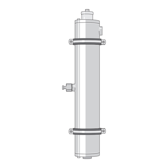
• ProMinent shall reject any warranty claims or claims for compensation in the event of damage during emergency operation of the UV system. - Page 19 Dulcodes UV-Desinfektionsanlage Control Lamp connection in systems that are equipped with a connector on the lamp cover. Fig. 2: Design of radiation chamber 1 Knurled nut 2 Retaining fixture for protective tube 3 Bleeder screw with O-ring 4 O-ring 5 UV-C sensor 6 Water drain plug with O-ring 7 Water inlet 8 UV lamp...
-
Page 20: Assembly And Installation
Dulcodes UV-Desinfektionsanlage Assembly and Installation Assembly and Installation Please take note of the following safety information prior to installation: WARNING! Make sure that • the maximum permissible water flow rate is not exceeded and • the UV transmission does not drop below the minimum permissible levels otherwise adequate disinfection will no longer be guaranteed! The maximum permissible water flow rate is defined in the supplied datasheet. -
Page 21: Hydraulic Connections
Dulcodes UV-Desinfektionsanlage Assembly and Installation 5.1.3 Hydraulic Connections ATTENTION! • Make the hydraulic connection of the radiation chamber in accordance with valid general guidelines as well as the locally applicable installation regulations. • Use UV-resistant material for the hydraulic connection! If PVC is used, it is possible that the PVC material may discolour in the area of the connection and even turn brittle under unfavourable conditions. - Page 22 Dulcodes UV-Desinfektionsanlage Assembly and Installation Fig. 3: Opening control unit ATTENTION! Use the appropriate tools to break out the blanked off cable leadthroughs on the underside of the control unit so as no to damage the pc-board and the thread. Break out blanked-off cable leadthroughs on the underside of the control unit First install the cables in the rear row: Fit screwed gland, thrust collar and seal from supplied supplementary kit on the cable, screw...
-
Page 23: Installing Lamp Protective Tubes
Dulcodes UV-Desinfektionsanlage Assembly and Installation Installing Lamp Protective Tubes ATTENTION! Examine for signs of damage before installing the lamp protective tubes! Do not install damaged protective tubes! Use supplied C-wrench to release the retaining fixtures for the protective tubes Remove retaining fixtures for protective tubes by turning out of the radiation chamber Fit supplied O-ring approx. -
Page 24: Start-Up
Calibrating UV-C Sensor The UV-C sensor is calibrated at the factory and does not need recalibration. If recalibration is required, please send the system in to ProMinent. IMPORTANT! Observe the supplementary instructions for special applications, in which the sensor signal is displayed in %. -
Page 25: Cleaning Lamp Protective Tubes
Dulcodes UV-Desinfektionsanlage Maintenance WARNING! • Replace the UV-C lamps after the maximum permissible useful life at the latest! Otherwise, operational reliability of the UV disinfection system can no longer be guaranteed. • The maximum permissible useful life is defined in the datasheet provided with the UV disinfection system. - Page 26 Dulcodes UV-Desinfektionsanlage Maintenance ATTENTION! Before installing, check the lamp protective tube for damage! A damaged protective tube must not be reinstalled. Check O-ring for damage. Replace damaged seal Fit O-ring approx. 40 mm over the open end of the lamp protective tube Insert lamp protective tube in radiation chamber ATTENTION! Make sure the protective tube is fitted correctly!
-
Page 27: Changing Uv Lamps
Dulcodes UV-Desinfektionsanlage Maintenance Open water drain plug and vent screw and remove Discharge radiation chamber Reinstall water drain plug and tighten, only very little force is required for this purpose Fill the radiation chamber with cleaning solution via the vent opening Allow the cleaning solution to soak in for at least 20 minutes Open water drain plug and remove Discharge (empty) radiation chamber and dispose of cleaning solution according to... -
Page 28: Calibrating Uv-C Sensor
Dulcodes UV-Desinfektionsanlage Maintenance Check whether the O-ring on the retaining fixture for the protective tube is fitted in the groove and is not damaged, replace damaged seal. Insert the new lamp in the protective tube and leave protruding by approx. 100 mm Plug in connector on UV lamp Systems with connector on UV lamp cover Switch off UV disinfection system with the START/STOP button... -
Page 29: Replacing Filter Mats
Dulcodes UV-Desinfektionsanlage Maintenance Replacing Filter Mats Replacing the filter mats of the fan and air outlet filter WARNING! Soiled filter mats of the fan and of the air outlet filter can cause overheating and irreparable damage to the control cabinet. The filter mats of the fan and of the air outlet filter should be replaced at least once per year. - Page 30 Dulcodes UV-Desinfektionsanlage Maintenance Fault: Lamp failed Fault Error message: xx lamp defective Confirm error message with ENTER key xx lamps defective Press CHANGE key to assume emergency mode (see 4.3.20) Lamp #xx Emergency mode: Lamp failed Emergency mode System continues operating in emergency mode xx lamps defective Lamp #xx Possible cause...
- Page 31 Dulcodes UV-Desinfektionsanlage Maintenance Error message: Memory error Fault Memory error Cause The control determined an error in the memory as part of the self-test Remedy Replace control unit (only by authorised electrician!) Error message: Basic setting Fault Basic setting Cause The control determined an error as part of the self-test Remedy Replace control unit (only by authorised electrician!)
-
Page 32: Terminal Connection Diagram - Dulcodes D, K, R And W
Dulcodes UV-Desinfektionsanlage Terminal Connection Diagram – Dulcodes D, K, R and W Terminal Connection Diagram – Dulcodes D, K, R and W Page 32... -
Page 33: Operation Log For Dulcodes Uv Disinfection System
Dulcodes UV-Desinfektionsanlage Form – Operation Log Page 33...
Need help?
Do you have a question about the Dulcodes D and is the answer not in the manual?
Questions and answers