
Related Manuals for Curtis G4TP1S63A3100


Summary of Contents for Curtis G4TP1S63A3100
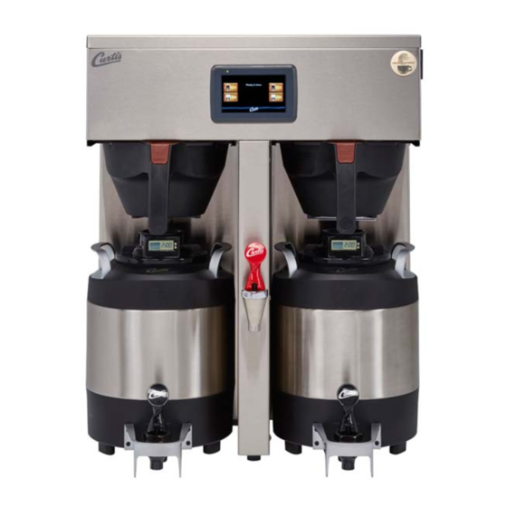
- Page 1 ® G4 ThermoPro Series 1 Gallon Coffee Brewing System : Please leave this booklet with the machine. 041217 FC25 - G4TP1, FRONT COVER F-10024 revNC...
-
Page 2: Table Of Contents
.......................ES52 ....................................................................................................................EC1 ..............................Contact Information Wilbur Curtis Co., Inc. 6913 Acco Street | Montebello, CA 90640 US Phone: 323-837-2300 | Toll Free: 800-421-6150 Email: csrassistance@wilburcurtis.com | Web: www.wilburcurtis.com . - 4:00 . PT Email: techsupport@wilburcurtis.com G4TP1 CONTENTS LIST... -
Page 3: Fs25
KEY FEATURES/SPECIFICATIONS/SYSTEM REQUIREMENTS FS25 Key Features ® • Gold Cup Series – digital control module provides precise control over all aspects of brewing: time, temperature, volume plus specialty coffee needs from pre-infusion to pulse-brewing to water bypass. • Generation Four (G4) Digital Control Module – Large, 4.3” touch screen. Icon-driven interface streamlines operation. -
Page 4: Is2
INSTRUCTIONS could result in personal injury or void the warranty. • This appliance is designed for commercial use. Any service other than cleaning and preventive maintenance should be performed by an authorized Wilbur Curtis service technician. • serviceable parts inside. - Page 5 IMPORTANT SAFEGUARDS CE Requirements • This appliance must be installed in locations where it can be overseen by trained personnel. • • • • This appliance must not be cleaned by water jet. • instruction concerning use of the appliance in a safe way and if they understand the hazards involved. •...
-
Page 6: Ii2
INSTALLATION INSTRUCTIONS WARNING: WARNING: properly grounded. NOTICE: SPECIFICATIONS section. IMPORTANT: Installation Instructions Installation Requirements • A secure surface capable of supporting the weight of the appliance. • For units without an attached cord set: Appropriately sized, UL listed, grounding type power cable to meet enough •... -
Page 7: Ii9
INSTALLATION INSTRUCTIONS Installation Leveling WARNING: Use the leveling legs to level the brewer only. Do not use them to adjust brewer height. Do not extend them higher than necessary. Position the brewer on the counter top. Level it left to right and front to back by turning the bottom of the legs. - Page 8 INSTALLATION INSTRUCTIONS Connect the Brewer Wiring (cont.) Brewers With A Cord Set Attached WARNING: Connect the power cord to the appropriate type and size electrical outlet. If the electrical outlet is not compatible with the power cord, have it upgraded by a licensed electrician. Do not modify the power plug.
-
Page 9: Oi7
OPERATING INSTRUCTIONS Brewing Instructions WARNING - TO AVOID SCALDING, AVOID SPLASHING. Keep body parts clear of the brewer during The G4 ThermoPro Brewer is factory preset for optimal performance. Back of brewer The brewer should be ON. Center an empty dispenser under the brew basket. -
Page 10: Ci1
CLEANING INSTRUCTIONS WARNING: HOT SURFACES - To avoid injury, allow the brewer and dispenser(s) to cool before cleaning. NOTICE - Do not use cleaning liquids, compounds or powders containing chlorine (bleach) or corrosives. USE OF THESE PRODUCTS WILL VOID THE WARRANTY. Cleaning The Brewer - Daily WARNING: DO NOT immerse the brewer in water or any other liquid. -
Page 11: Ci5
CLEANING INSTRUCTIONS Cleaning the 1.0 Gallon or 1.5 Gallon Thermal Dispensers (Daily) WARNING: DO NOT immerse the thermal server or its lid assembly in water or any other liquid. Do not place the thermal server or lid in a dishwasher. Placing a thermal server in a dishwasher will void the warranty. To avoid damage, DO NOT use a brush to clean the faucet or the inside of the faucet shank (outlet). - Page 12 CLEANING INSTRUCTIONS Cleaning the Faucet Parts and Gauge Glass (cont.) Sanitize - After rinsing, place all faucet and gauge parts in a sink to be sanitized. Immerse them in a commercial sanitizer suitable for food grade applications. Sanitize according to the W ASH directions on the package.
-
Page 13: Ci9
CLEANING INSTRUCTIONS Cleaning the Airpot/Pour Pot (Daily) WARNING: DO NOT immerse the airpot/pour pot or lid assembly in water or any other liquid. Do not place the airpot/pour pot or lid in a dishwasher. Placing a airpot or pour pot in a dishwasher will void the warranty. Start by preparing a mild solution of detergent and warm water. - Page 14 Control symbols - all symbols may not be present at the same time Return to Home Undo Curtis logo Scroll left/right previous Entering Programming Mode The ACCESS CODE screen will appear. The menu icons. The icons vary based on the model appear.
- Page 15 PROGRAMMING GUIDE Programming SELECTIONS FOR COFFEE BREWER MODELS Model Select Recipes Control Settings Brew Settings Settings Summary Exit Coffee Gemini Gemini IF One Batch Single Gourmet Std ThermoPro Two Batch Twin Light Roast Milano By Volume/Time Three Batch Dark Roast Pre/Pulse Omega High Yield...
- Page 16 PROGRAMMING GUIDE USB - Easy Programming program each step individually using the touchscreen. This process also makes it easy to quickly standardize the IMPORTANT: completely Uploading the Software to the Flash Drive as desired. Downloading the Software to the Brewer from the Flash Drive Select the (identical) brewer you wish to make program changes to.
- Page 17 ROUGH-IN DRAWINGS RD31 G4TP1S - Single Coffee Brewer * Brew Basket WC-3417 (standard) 20.75 in ** Brew Basket WC-3422 (high volume) [52.7 cm] 11.07 in 18.00 in [28.1 cm] [45.7 cm] 24.73 in [62.8 cm] 20.66 in 13.40 in* [52.5 cm] [34.0 cm] 12.93 in** 8.00 in...
-
Page 18: Ip46
ILLUSTRATED PARTS LIST IP46 Supplies and Accessories - All Models WC-29050 - Spray Head CAB-1 - Cleaning Brush G4TP1S - Main Chassis - Exploded View Water tanks assemblies - See section IP47 for domestic/Canadian models - See section IP48 for other export models 1 1A 1 1B... - Page 19 TRANSFORMER,120VAC-24V 4.8A W/ LEADS & WC-589-101 1 MOLEX CONNECTOR TRANSFORMER,240VAC- 24V 4.8VA W/LEADS & WC-589-102 2 MOLEX CONNECTOR 1 G4TP1S63A3100 2 G4TP1S30A3100 b Units built before 05/15/17. G4TP1S - Recommended Parts to Stock ITEM # PART # DESCRIPTION ITEM #...
- Page 20 ILLUSTRATED PARTS/RECOMMENDED PARTS IP46 G4TP1T - Main Chassis - Exploded View Water tank assembly, see section IP26 G4TP1, ILLUSTRATED PARTS/RECOMMENDED PARTS 060117A...
- Page 21 ILLUSTRATED PARTS LIST IP46 G4TP1T - Main Chassis - Parts List ITEM # PART # DESCRIPTION ITEM # PART # DESCRIPTION WC-37122 1 KIT, DUMP VALVE RIGHT WC-29044 SLEEVE, OVERFLOW ASSY GEN USE VALVE, BREW DUMP RIGHT 240V 12W KIT, INLET VALVE REPAIR USE ON WC-826/ WC-854 2 WC-3765L GEM12D/TP/TPC...
-
Page 22: Ip47
ILLUSTRATED PARTS LIST IP47 WC-62088DV(-20) - Tank Assembly WC-62088DV(-20) - Tank Assembly - Parts List ITEM # PART # DESCRIPTION ITEM # PART # DESCRIPTION TANK, COMPLETE G4TP1S63 (2) GUARD, SHOCK/HEATING ELEMENT FOR SIN- WC-62088DV 1 WC-4394 1600W-120V/220V GLE HEATING ELEMENT TANK, COMPLETE G4TP1S52 (2) 1450W-120V THERMOSTAT, HI LIMIT HEATER CONTROL WC-62088DV-20 2... -
Page 23: Ip48
ILLUSTRATED PARTS LIST IP48 WC-62088 - Tank Assembly WC-62088 - Tank Assembly - Parts List ITEM # PART # DESCRIPTION ITEM # PART # DESCRIPTION WC-62088 TANK, COMPLETE G4TP1S10/30 (2) 2000W-220V THERMOSTAT, HI LIMIT HEATER CONTROL WC-522 DPST 277V 40A WC-5853-102 COVER, TOP HEATING TANK GEN USE WC-43055... -
Page 24: Ip26
ILLUSTRATED PARTS/RECOMMENDED PARTS IP26 WC-62033 - Tank Assembly WC-62033 - Tank Assembly - Parts List ITEM # PART # DESCRIPTION ITEM # PART # DESCRIPTION WC-54287 TANK, ASSY TPS1T/GEMTS WC-4382 GUARD, SHOCK HTNG ELMNT DOUBLE WC-62033 TANK, COMPLETE GEMTS W/ULTEM FITTINGS THERMOSTAT, HI LIMIT HEATER CONTROL DPST WC-522 277V 40A... -
Page 25: Es41
ELECTRICAL SCHEMATICS ES41 G4GEMS63A1000, G4TP1S63A3100, G4TP2S63A3100, G4TP2S63A3500 GTPSG4-63, ELECTRICAL SCHEMATIC 041817A... - Page 26 ELECTRICAL SCHEMATICS ES50 G4TP1S30A3100, G4TP2S30A3100 GTPSG4-30, ELECTRICAL SCHEMATIC 041917A...
-
Page 27: Es42
ELECTRICAL SCHEMATICS ES42 G4GEMT10A1000, G4TP1T10A3100, G4TP2T10A3100, G4TP2T10A3500 GTPTG4-10, ELECTRICAL SCHEMATIC 053117A... -
Page 28: Es52
ELECTRICAL SCHEMATICS ES52 G4TP1T30A3100, G4TP2T30A3100 GTPTG4-30, ELECTRICAL SCHEMATIC 053117A... - Page 29 TROUBLESHOOTING GUIDE WARNING: Electric Shock Hazard - Scald and Burn Hazard - IMPORTANT: always check all Valve Test Procedure Troubleshooting Guidelines • • • • Valve Test Procedure in either direction Water Not Hot Enough replace the temperature sensor Water Heats More Slowly Than Usual During Brewing...
- Page 30 TROUBLESHOOTING GUIDE No Power - Display Not Lit Water Tank Does Not Fill Brewer Does Not Start When Brew Button is Pressed Brewing Brewing Water Too Hot (Boiling or Excessive Steaming) IMPORTANT: Over Temp Over Temp Sensor or Ready to Brew Sensor Error Message Heating Heating...
- Page 31 TROUBLESHOOTING GUIDE Water Tank Does Not Fill IMPORTANT: Coffee/Tea Too Strong Dispenser Not Filled To Normal Level During Brewing Dispenser Not Filled To Normal Level During Brewing sure that the spray head is correctly aligned and that the tubing is routed properly to allow for maximum water...
- Page 32 TROUBLESHOOTING GUIDE All Of The Time No Water/Tea Flows From Brewer During Brewing Water Tank Does Not Fill Low Water Flow Warning Water Level Error Message Water Level Error Message “Internal Error 1” Message on Display “Internal Error 2” Message on Display PROGRAMMING GUIDE...
- Page 33 TROUBLESHOOTING GUIDE Water Does Not Heat At All Check to see if the water level in the tank is in contact with the water level probe. If not, see Tank Does Not Fill. • The water will not heat unless it is in contact with the probe. If the water heats, but is not hot enough, see Water Not Hot Enough.
- Page 34 The G4 control module diagnostics can be used to detect electrical circuit failures in the brewer. When a circuit Using the Diagnostics The MAIN MENU Control Settings. Diagnostics Curtis logo Auto Test to test all circuits. If a button is highlighted green the DIAGNOSTICS Left Auto Test...
-
Page 35: Ec1
ERROR CODES Warning Messages - Allows Brewer to Continue Brewing MESSAGE DISPLAY WARNING DESCRIPTION CAUSE Brew count “Gallons Since Reset” exceeds programmed Maintenance Required Maintenance Required preventative maintenance period. If the Inlet valve remains on longer than XX seconds (during the brew cycle only) and repeats TWICE during that brew cycle. - Page 36 Return Merchandise Authorization (RMA): All returned equipment must be properly re-packaged in the original carton and received by Curtis within 45 days following the issuance of a RMA. NO UNITS OR PARTS WILL BE ACCEPTED WITHOUT A RETURN MERCHANDISE AUTHORIZATION (RMA).
Need help?
Do you have a question about the G4TP1S63A3100 and is the answer not in the manual?
Questions and answers