Table of Contents
Advertisement
Available languages
Available languages
C7-Ein-/Ausgabebaugruppe
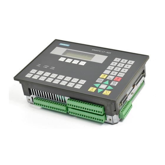
C7 Input/Output Module
Deutsch
Diese Produktinformation enthält Ergänzungen zum Produkt. Sie ist als separater Bestandteil aufzufas-
sen und in Zweifelsfällen in der Verbindlichkeit anderen Aussagen in Handbüchern und Katalogen über-
geordnet.
English
This Product Information contains additional information about the product. It is a separate component
and, in cases of doubt, shall take precedence over other statements in manuals and catalogs.
Änderungen vorbehalten
Subject to alteration
Produktinformation / Product Information
C79000-Z7074-C630-01
6ES7 630-0DA00-0AB0
1
Advertisement
Table of Contents

Subscribe to Our Youtube Channel
Related Manuals for Siemens SIMATIC C7


Summary of Contents for Siemens SIMATIC C7
- Page 1 C7-Ein-/Ausgabebaugruppe 6ES7 630-0DA00-0AB0 C7 Input/Output Module Deutsch Diese Produktinformation enthält Ergänzungen zum Produkt. Sie ist als separater Bestandteil aufzufas- sen und in Zweifelsfällen in der Verbindlichkeit anderen Aussagen in Handbüchern und Katalogen über- geordnet. English This Product Information contains additional information about the product. It is a separate component and, in cases of doubt, shall take precedence over other statements in manuals and catalogs.
-
Page 2: Table Of Contents
C7-Ein-/Ausgabebaugruppe / C7 Input/Output Module Hinweise ............. . Technische Beschreibung der C7–Ein-/Ausgabebaugruppe . -
Page 3: Hinweise
C7-Ein-/Ausgabebaugruppe / C7 Input Output Module Hinweise Inhalt Die C7-Ein-/Ausgabebaugruppe hat nachfolgend beschriebene Besonderheiten. Ausgabestände C7-Ein-/Ausgabebaugruppe 6ES7 630-0DA00-0AB0 Freigegeben für den Anschluß an: C7-623/A, C7-626/A, C7-623/P, C7-624/P, C7-626/P, C7-626/P DP, C7-633/P, C7-633 DP, C7-634/P, C7-634 DP Allgemein Die C7-Ein-/Ausgabebaugruppe entspricht in den technischen Daten der Peripherie der C7 63x/P-Geräte. - Page 4 C7-Ein-/Ausgabebaugruppe / C7 Input/Output Module Konfiguration in Die C7-Ein-/Ausgabebaugruppe ist derzeit noch nicht im Hardwarekatalog von STEP 7 STEP7-Hardwarekonfiguration enthalten. Zum Konfigurieren der C7-Ein–/Ausga- bebaugruppe kopieren Sie die Peripherie vom Steckplatz 4 und 5 eines C7-63x/P- Projektes auf die Steckplätze 6 und 7 (bei Anschluß an C7-62x bzw. C7-63x/P) bzw.
-
Page 5: Technische Beschreibung Der C7-Ein-/Ausgabebaugruppe
C7-Ein-/Ausgabebaugruppe / C7 Input Output Module Technische Beschreibung der C7-Ein-/Ausgabebaugruppe Einbauen und Vorbereiten Lieferbestand- Folgende Komponenten gehören zum Lieferumfang der C7-Ein-/Ausgabebau- teile gruppe: 1 C7-Ein-/Ausgabebaugruppe 2 Erdungsbügel (1 x U-Form, 1 x L-Form) 16 Schirmklemmen 10 Befestigungsschrauben 1 Steckersatz 2 Kabelabdeckungen (1 x C7-62x/P bzw. C7-63x/P; 1 x C7-63x DP) 1 Satz Beschriftungsaufkleber für Montage am C7-62x/P 1 Aufkleber für Grundgerätausgabestände Produktinformation / Product Information... -
Page 6: Einbauen Der C7-Ein-/Ausgabebaugruppe
C7-Ein-/Ausgabebaugruppe / C7 Input/Output Module 2.1.1 Einbauen der C7-Ein-/Ausgabebaugruppe Aufkleber für Dieser Aufkleber sollte verwendet werden, um die Ausgabestände vom Typen- Grundgerätaus- schild des Grundgerätes auf die C7-Ein–/Ausgabebaugruppe zu übertragen, da gabestände diese bei montierter Baugruppe nicht mehr sichtbar sind. Dieser Aufkleber sollte dann unterhalb des Baugruppentypenschildes aufgeklebt werden. -
Page 7: Einrichten Des Elektrischen Aufbaus Und Steckerbelegung
C7-Ein-/Ausgabebaugruppe / C7 Input Output Module 2.1.2 Einrichten des elektrischen Aufbaus und Steckerbelegung Übersicht Für den Anschluß der Ein- und Ausgänge der C7-Ein-/Ausgabebaugruppe stehen die erforderlichen Stiftleisten (Schnittstellen) zur Verfügung. Analogeingänge (Gehäusebeschriftung: ”Analog Input”) Analogausgänge Digitaleingänge (Gehäusebeschriftung: (Gehäusebeschriftung: ”Analog Output”) ”Digital Input 24V DC”) Stromversorgung für die Digi- taleingänge und -ausgänge... - Page 8 C7-Ein-/Ausgabebaugruppe / C7 Input/Output Module Bohrungen zum Verschrauben Kabelabdeckung mit dem C7-Gehäuse Funktionserde DC 24V-Stromversorgung (Gehäusebeschriftung: ”Input 24V DC 2.4A”) Bild 1-2 Ansicht der C7-Ein-/Ausgabebaugruppe mit Stromversorgung DC 24V-Strom- Die Stiftleiste ”DC 24V-Stromversorgung” der C7-Ein-/Ausgabebaugruppe ist wie versorgung folgt belegt: Pin-Nr.
-
Page 9: Aufbaurichtlinien Für Störungssicheren Aufbau
C7-Ein-/Ausgabebaugruppe / C7 Input Output Module 2.1.3 Aufbaurichtlinien für störungssicheren Aufbau Aufbaurichtlinien Es gelten dieselben Aufbaurichtlinien wie für das angeschlossene Komplettgerät. 2.1.4 Geschirmte Leitungen anschließen Übersicht In diesem Abschnitt ist beschrieben, wie Sie den Schirm von geschirmten Signallei- tungen mit Erde verbinden. Die Verbindung zur Erde wird erreicht über einen Er- dungsbügel, der den Schirm direkt mit der Erde der C7-Ein-/Ausgabebaugruppe verbindet. -
Page 10: Ergänzung Zu Technischen Daten
C7-Ein-/Ausgabebaugruppe / C7 Input/Output Module Befestigung für Erdungsbügel U-Form Befestigung der Erdungs- schiene L–Form Bild 1-3 C7-Ein-/Ausgabebaugruppe mit Erdungsbügel und Schirmklemmen Ergänzung zu Technischen Daten Elektromagnetische Vertäglichkeit (EMV) Störaussendung Klasse A nach EN 55022 Grenzwertklasse Leitungsgeführte Stör- 1 kV nach IEC 1000–4–4 Burst größen auf Spannungs- versorgungsleitungen Produktinformation / Product Information... -
Page 11: Digitaleingänge Und -Ausgänge Der C7-Ein-/Ausgabebaugruppe
C7-Ein-/Ausgabebaugruppe / C7 Input Output Module Digitaleingänge und -ausgänge der C7-Ein-/Ausgabebau- gruppe Übersicht Die Digitaleingänge und -ausgänge der C7-Ein-/Ausgabebaugruppe haben diesel- ben technischen Daten und Eigenschaften wie die Digitalperipherie C7-6xx/P mit folgender Ausnahme: Im ”DI/DO”-Bild der mit ProTool gelieferten Standardprojektierung wird aus- schließlich die digitale Onboard-Peripherie des Grundgerätes angezeigt, nicht die digitale Peripherie der C7-Ein-/Ausgabebaugruppe. -
Page 12: Konfigurieren Und Adressieren Der C7-Ein-/Ausgabebaugruppe
C7-Ein-/Ausgabebaugruppe / C7 Input/Output Module Konfigurieren und Adressieren der C7-Ein-/Ausgabebau- gruppe 2.6.1 Konfigurieren eines Aufbaus mit C7-Ein-/Ausgabebau- gruppe Übersicht Beim Konfigurieren mit STEP7 legen Sie fest, welche Baugruppen Sie in Ihrer Anlage einsetzen und wie Sie diese in den einzelnen Baugruppenträgern anordnen. Diese Anordnung tragen Sie in die Konfigurationstabelle ein und speichern diese anschließend ab. - Page 13 C7-Ein-/Ausgabebaugruppe / C7 Input Output Module Ansicht untere Seite Digitaleingänge Adresse 8.0 Adresse 8.1 Byteadresse: Digitaleingänge und -ausgänge Anfangsadresse Byte 8 Adresse 8.7 Adresse 9.0 Adresse 9.1 Byteadresse: Digitaleingänge und -ausgänge Anfangsadresse Digitalausgänge Byte 9 Adresse 9.7 24 V für DI Masse für DI Laststromversorgung für +24 V...
- Page 14 C7-Ein-/Ausgabebaugruppe / C7 Input/Output Module Ansicht untere Seite Digitaleingänge Adresse 0.0 Adresse 0.1 Byteadresse: Digitaleingänge und -ausgänge Anfangsadresse Byte 0 Adresse 0.7 Adresse 1.0 Adresse 1.1 Byteadresse: Digitaleingänge und -ausgänge Anfangsadresse Digitalausgänge Byte 1 Adresse 1.7 24 V für DI Masse für DI Laststromversorgung für +24 V...
- Page 15 C7-Ein-/Ausgabebaugruppe / C7 Input Output Module 24 V intern Prinzipschaltbild Digitaleingänge Prinzipschaltbild Digitalausgänge Bild 1-6 Prinzipschaltbilder der Digitalein–/ ausgänge Produktinformation / Product Information C79000-Z7074-C630-01...
-
Page 16: Pinbelegung Und Adressieren Der Analogperipherie
C7-Ein-/Ausgabebaugruppe / C7 Input/Output Module 2.6.3 Pinbelegung und Adressieren der Analogperipherie Adressen der Die Adressierung eines Analogkanals erfolgt immer wortweise. Analogfunktio- Bild 1-7 zeigt, welche Kanaladressen sich ergeben. Sie sehen, daß bei der Analog- peripherie die Analogeingabekanäle und der Analogausgabekanal ab der gleichen Adresse, der Anfangsadresse, adressiert werden. - Page 17 C7-Ein-/Ausgabebaugruppe / C7 Input Output Module Ansicht rechte Seite Analogeingänge Spannungsmessung Strommessung AI1-U AI1-I AI1-M AI2-U AI2-I AI2-M AI3-U AI3-I AI3-M AI4-U AI4-I AI4-M Analogausgänge Spannungsausgang Stromausgang Anschlußbild Pin–Bezeichnung Teile mit dieser Schraffur sind für dieses Beispiel nicht relevant. Bild 1-8 Pinbelegung und Anschlußbild der Analogein–...
-
Page 18: Pinbelegung Und Adressieren Der Universaleingänge
C7-Ein-/Ausgabebaugruppe / C7 Input/Output Module 2.6.4 Pinbelegung und Adressierung der Universaleingänge Ansicht untere Seite bei Anschluß an C7-6xx/P bei Anschluß an C7-63x DP Eingänge mit dieser Schraf- fur sind für dieses Beispiel nicht relevant Pin-Bezeichnung Universaleingänge DI–X1 Adresse 319.0* bzw. 287.0** DI–X2 Adresse 319.1* bzw. -
Page 19: Notes
C7-Ein-/Ausgabebaugruppe / C7 Input Output Module Notes Contents The C7 input/output module has the special features described below. Releases C7 input/output module 6ES7 630-0DA00-0AB0 Released for connection to: C7-623/A, C7-626/A, C7-623/P, C7-624/P, C7-626/P, C7-626/P DP, C7-633/P, C7-633 DP, C7-634/P, C7-634 DP General The C7 input/output module has the same technical specifications as the I/O of the C7 63x/P devices. - Page 20 C7-Ein-/Ausgabebaugruppe / C7 Input/Output Module Configuration in The C7 input/output module is currently not included in the hardware catalog of the STEP 7 STEP7 hardware configuration. To configure the C7 input/output module, copy the I/O from slots 4 and 5 of a C7-63x/P project to slots 6 and 7 (in the case of connec- tion to a C7-62x or C7-63x/P) or to slots 4 and 5 (in the case of connection to a C7-63x DP): C7-623/P, C7-624/P, C7-626/P, C7-626/P DP,...
-
Page 21: Technical Description Of The C7 Input/Output Module
C7-Ein-/Ausgabebaugruppe / C7 Input Output Module Technical Description of the C7 Input/Output Module Installing and Preparing Components The following components are shipped with the C7 input/output module: 1 C7 input/output module 2 ground clamp (1 x U shape, 1 x L shape) 16 shield terminals 10 fixing screws 1 connector set... -
Page 22: Installing The C7 Input/Output Module
C7-Ein-/Ausgabebaugruppe / C7 Input/Output Module 4.1.1 Installing the C7 Input/Output Module Sticker for Basic This sticker should be used to transfer the output states from the type plate of the Device Output basic device to the C7 input/output module, since these are no longer visible when States the module is installed. -
Page 23: Electrical Configuration And Pinouts
C7-Ein-/Ausgabebaugruppe / C7 Input Output Module 4.1.2 Electrical Configuration and Pinouts Overview The C7 input/output module has ports (male connectors) for connecting the inputs and outputs. Analog inputs (Labeled: ”Analog Input”) Analog outputs Digital inputs (Labeled: (Labeled: ”Analog Output”) ”Digital Input 24V DC”) Power supply for the digital in- puts and outputs (Labeled: ”DI/DO-... - Page 24 C7-Ein-/Ausgabebaugruppe / C7 Input/Output Module Holes for securing to the C7 housing Cable cover Functional ground DC 24 V power supply (Labeled: “Input 24V DC 2.4A”) Bild 1-11 View of the C7 Input/Output Module with Power Supply 24 V DC Power The “24 V DC Power supply”...
-
Page 25: Guidelines For Problem-Free Installation
C7-Ein-/Ausgabebaugruppe / C7 Input Output Module 4.1.3 Guidelines for Problem-Free Installation Overview The guidelines are the same as those for the connected control systems. 4.1.4 Connecting Shielded Cables Overview This section describes how to connect the shield of shielded signal cables to ground. -
Page 26: Addition To Technical Specifications
C7-Ein-/Ausgabebaugruppe / C7 Input/Output Module Location for securing the grounding strip U shape Location for securing the grounding strip L shape Bild 1-12 C7 Input/Output Module with Grounding Strip and Shield Clips Addition to Technical Specifications Electromagnetic Compatibility (EMC) Emitted interference class Class A to EN 55022 Conducted interference 1 kV to IEC 1000-4-4 burst on power supply lines... -
Page 27: Digital Inputs And Outputs Of The C7 Input/Output Module
C7-Ein-/Ausgabebaugruppe / C7 Input Output Module Digital Inputs and Outputs of the C7 Input/Output Module Overview The digital inputs and outputs of the C7 input/output module have the same technical data and properties as the digital I/Os C7-6xx/P of the connected control system with the following exception: In the “DI/DO”... -
Page 28: Configuring And Addressing The C7 Input/Output Module
C7-Ein-/Ausgabebaugruppe / C7 Input/Output Module Configuring and Addressing the C7 Input/Output Module 4.6.1 Configuring with a C7 Input/Output Module Overview When you configure with STEP 7, you specify which modules you are using in your system and how these are arranged in the individual racks. You enter this arrangement in the configuration table and save it. - Page 29 C7-Ein-/Ausgabebaugruppe / C7 Input Output Module View of lower side Digital inputs Address 8.0 Address 8.1 Byte address: Digital inputs and outputs Start address byte 8 Address 8.7 Address 9.0 Address 9.1 Byte address: Digital inputs and outputs Start address byte 9 Digital outputs Address 9.7 24 V for DI...
- Page 30 C7-Ein-/Ausgabebaugruppe / C7 Input/Output Module View of lower side Digital inputs Address 0.0 Address 0.1 Byte address: Digital inputs and outputs Start address byte 0 Address 0.7 Address 1.0 Address 1.1 Byte address: Digital inputs and outputs Start address byte 1 Digital outputs Address 1.7 24 V for DI...
- Page 31 C7-Ein-/Ausgabebaugruppe / C7 Input Output Module 24 V internal Basic circuit diagram of the digital inputs Basic circuit diagram of the digital outputs Bild 1-15 Basic Circuit Diagrams of the Digital Inputs/Outputs Produktinformation / Product Information C79000-Z7074-C630-01...
-
Page 32: Pinout And Addressing Of The Analog I/Os
C7-Ein-/Ausgabebaugruppe / C7 Input/Output Module 4.6.3 Pinout and Addressing of the Analog I/Os Addresses of the An analog channel is always addressed word by word. Analog Func- Figure 1-16 shows which channel addresses are obtained. You will see that, in the tions case of the analog I/Os, the analog input channels and the analog output channel are addressed as of the same address, the start address. - Page 33 C7-Ein-/Ausgabebaugruppe / C7 Input Output Module View of right side Current mea- Analog inputs Voltage measurement surement AI1-U AI1-I AI1-M AI2-U AI2-I AI2-M AI3-U AI3-I AI3-M AI4-U AI4-I AI4-M Analog outputs Voltage measurement Current output Terminal as- signment dia- Pin designations gram Parts with this shading have no rele- vance to this example...
-
Page 34: Pinout And Addressing Of The Universal Inputs
C7-Ein-/Ausgabebaugruppe / C7 Input/Output Module 4.6.4 Pinout and Addressing of the Universal Inputs View of lower side Connection to C7-6xx/P Connection to C7-63x DP Inputs with this shading have no relevance to this example Pin designations Universal inputs DI–X1 Address 319.0* or 287.0** DI–X2 Address 319.1* or 287.1** Address 319.2* or 287.2**...
Need help?
Do you have a question about the SIMATIC C7 and is the answer not in the manual?
Questions and answers