Table of Contents
Advertisement
Advertisement
Table of Contents

Related Manuals for MrCool MST03


Summary of Contents for MrCool MST03
- Page 1 ® MRCOOL Universal WiFi Thermostat ®...
- Page 3 Contents APPLICATION ----------------------------------------------------- 1 FEATURES ------------------------------------------------------- 2 SPECIFICATIONS -------------------------------------------------- 3 INSTALLATION ---------------------------------------------------- 5 WIRING -------------------------------------------------------- 13 POWERING THE THERMOSTAT ----------------------------------------- 30 INSTALLER SETUP ------------------------------------------------ 32 OPERATION ----------------------------------------------------- 44 PROGRAMMING -------------------------------------------------- 64 FCC Note ------------------------------------------------------- 70 TROUBLESHOOTING ---------------------------------------------- 72...
- Page 5 MRCOOL® provides temperature control for gas, oil, electric and heat pumps for up to 3 heating and 2 cooling systems. Not only can you remotely monitor and control the heating and cooling system in your home or business — you can stay...
- Page 6 FEATURES • Large, clear display with backlight shows temperature, set temperature and humidity. • Menu-driven programming makes setup effortless. • Beautiful ergonomic design is smart and sophisticated to match your lifestyle. • Touchscreen capability. • Connect to the Internet to monitor and control your heating/cooling system •...
- Page 7 SPECIFICATIONS Temperature Setting Range Heating: 40°F to 90°F ( 4°C to 32°C). Cooling: 50°F to 99°F (10°C to 37°C). Operating Ambient Temperature: 32°F to 122°F (0°C to 50°C). Shipping Temperature: 14°F to 140°F ( -10°C to 60°C). Operating Relative Humidity (Non -condensing): IRS –1: 5% to 95%.
- Page 8 +/- 2 minute per month. Cool Indication: Show "Cool On" on the screen when Cool is activated. Heat Indication: Show "Heat On" on the screen when Heat is activated. Auxiliary Heat Indication: Show "Aux On" on the screen when Auxiliary Heat is activated.
- Page 9 INSTALLATION When Installing this Product 1. Read these instructions carefully. Failure to follow the instructions can damage the product or cause hazardous conditions. 2. Check the ratings given in the instructions to make sure the product is suitable for your application.
- Page 10 ---Unheated or uncooled areas such as an outside wall behind the thermostat. Mounting Means: Mounts directly on the wall in the living space using mounting screws and anchors provided. Dimensions: MRCOOL® dimensions: see Fig. 1. MRCOOL® back case: see Fig. 2. MRCOOL® cover plate: see Fig. 3.
- Page 11 Fig. 1. Thermostat Dimensions in inches. (mm)
- Page 12 Fig. 2. Thermostat back case dimensions in inches. (mm).
- Page 13 Fig. 3. Thermostat cover plate dimensions in inches. (mm).
- Page 14 Fig.4. Selecting thermostat location.
- Page 15 Installing Wall plate CAUTION Electrical hazard can cause electrical shock or equipment damage. Disconnect power before wiring. The thermostat can be mounted horizontally on the wall. 1. Position and level the wall plate (for appearance only). 2. Use a pencil to mark the mounting holes. 3.
- Page 16 Fig.5. Mounting wall plate.
- Page 17 WIRING All wiring must comply with local electrical codes and ordinances. 1. See Table 1 and Fig.6 for terminal designation descriptions. Insert wires in the terminal block under the loosened screw. See Fig.7. 2. Securely tighten each screw. 3. Push excess wire back into the hole. 4.
- Page 18 Table 1. Terminal Designation Descriptions. Terminal Designation Description Power for cooling--connect to secondary side of cooling system RC (s ee Note 1) transformer Power for heating--connect to secondary side of heating system R (see Note 1) transformer C (see Note 2) Common wire from secondary side of cooling system transformer Compressor contactor F an relay...
- Page 19 NOTES: 1. When used in a single -transformer system, leave metal jumper wire in place between RC and R. If used on a two -transformer system, remove metal jumper wire between RC and R. 2. If thermostat is configured for a heat pump system, configure changeover valve for cool or heat.
- Page 20 Fig.7. Inserting wires in terminal block. IMPORTANT: Use 18 gauge thermostat wire.
- Page 21 1. POWER SUPPLY. PROVIDE DISCONNECT MEANS AND OVERLOAD PROTECTION AS REQUIRED. 2. FACTORY INSTALLED JUMPER. Fig. 8. Typical hookup of conventional single-stage heat and cool system with single transformer (1H/1C conventional).
- Page 22 1. POWER SUPPLY. PROVIDE DISCONNECT MEANS AND OVERLOAD PROTECTION AS REQUIRED. 2. FACTORY INSTALLED JUMPER. Fig. 9. Typical hookup of conventional single -stage heat and cool system with two transformers (1H/1C conventional).
- Page 23 1. POWER SUPPLY. PROVIDE DISCONNECT MEANS AND OVERLOAD PROTECTION AS REQUIRED. 2. FACTORY INSTALLED JUMPER. Fig. 10. Typical hookup of heat -only system (1H conventional).
- Page 24 1. POWER SUPPLY. PROVIDE DISCONNECT MEANS AND OVERLOAD PROTECTION AS REQUIRED. 2. FACTORY INSTALLED JUMPER. Fig. 11. Typical hookup of heat only system with fan (1H conventional).
- Page 25 1. POWER SUPPLY. PROVIDE DISCONNECT MEANS AND OVERLOAD PROTECTION AS REQUIRED. 2. FACTORY INSTALLED JUMPER. Fig. 12. Typical hookup of heat only power to open and power to close zone valve system.
- Page 26 1. POWER SUPPLY. PROVIDE DISCONNECT MEANS AND OVERLOAD PROTECTION AS REQUIRED. 2. FACTORY INSTALLED JUMPER. Fig. 13. Typical hookup of heat only system with normally open zone valves.
- Page 27 1. POWER SUPPLY. PROVIDE DISCONNECT MEANS AND OVERLOAD PROTECTION AS REQUIRED. 2. FACTORY INSTALLED JUMPER. Fig. 14. Typical hookup of cool only system (1C conventional).
- Page 28 1. POWER SUPPLY. PROVIDE DISCONNECT MEANS AND OVERLOAD PROTECTION AS REQUIRED. 2. FACTORY INSTALLED JUMPER. Fig. 15. Typical hookup of conventional multi-stage two-stage heating and two-stage cooling in a single-transformer system (2H/2C, 2H/1C or 1H/2C conventional).
- Page 29 1. POWER SUPPLY. PROVIDE DISCONNECT MEANS AND OVERLOAD PROTECTION AS REQUIRED. 2. FACTORY INSTALLED JUMPER. Fig. 16. Typical hookup of conventional multi-stage two-stage heating and two-stage cooling in a two-transformer system (2H/2C, 2H/1C or1H/2C conventional).
- Page 30 1. POWER SUPPLY. PROVIDE DISCONNECT MEANS AND OVERLOAD PROTECTION AS REQUIRED. 2. FACTORY INSTALLED JUMPER. 3. "O/B" TERMINAL SET TO CONTROL AS EITHER "O" OR "B" IN THE INSTALLER SETUP. Fig. 17. Typical hookup of single -stage heat pump with no auxiliary/backup heat (1H/1C heat pump).
- Page 31 1. POWER SUPPLY. PROVIDE DISCONNECT MEANS AND OVERLOAD PROTECTION AS REQUIRED. 2. FACTORY INSTALLED JUMPER. 3. MUST CONNECT THE 24VAC COMMON WHEN USING L. THE TERMINAL IS SHOWN AS EQUIPMENT MONITOR 4. "O/B" TERMINAL SET TO CONTROL AS EITHER "O" OR "B" IN THE INSTALLER SETUP. Fig.
- Page 32 1. POWER SUPPLY. PROVIDE DISCONNECT MEANS AND OVERLOAD PROTECTION AS REQUIRED. 2. FACTORY INSTALLED JUMPER. 3. MUST CONNECT THE 24VAC COMMON WHEN USING L. THE TERMINAL IS SHOWN AS EQUIPMENT MONITOR. 4."O/B" TERMINAL SET TO CONTROL AS EITHER "O" OR "B" IN THE INSTALLER SETUP. Fig.
- Page 33 1. POWER SUPPLY. PROVIDE DISCONNECT MEANS AND OVERLOAD PROTECTION AS REQUIRED. 2. FACTORY INSTALLED JUMPER. 3. MUST CONNECT THE 24VAC COMMON WHEN USING L. THE TERMINAL IS SHOWN AS EQUIPMENT MONITOR. 4. "O/B" TERMINAL SET TO CONTROL AS EITHER "O" OR "B" IN THE INSTALLER SETUP. Fig.
- Page 34 POWERING THE THERMOSTAT Wiring 24VAC Common ·Single-Transformer System: Connect the common side of the transformer to the C screw terminal of the thermostat wall plate. Leave the metal jumper wire in place between RC and R. ·T wo-Transformer System: Connect the common side of the cooling transformer to the C screw terminal of the thermostat wall plate.
- Page 35 Fig. 21. Mount thermostat to wall plate.
- Page 36 INSTALLER SETUP Follow these steps to enter the Installer Setup: 1. See Fig. 22-1. Press and release Key. System mode will blink, Fig.22-1 then press and hold the key for approximately 5 s econds until the screen changes. Menu numbers will display at bottom right corner.
- Page 37 2. Press key to cutover the installer setup, or press exit without saving changes. submenu, and press key enter submenu. Under submenu use to set parameters. See Fig. 22-3. Fig. 22-3. Note: See Tables 2 for the Installer Setup Numbers and Settings. 3.Press key to exit and confirm...
- Page 38 Table 2.installer Setup Menu. Number Name Settings Notes MAC and 0140 See MAC and firmware version version 0150 Date and time Set calendar date and time Schedule 0-non-programmable The schedule setting will 0160 Options 1-7 day programmable default if changed...
- Page 39 Number Name Settings Notes 1-1heat/1cool conventional ( d efault setting) 2-single-stage heat pump (no auxiliary heat) 3-heat only conventional (no fan) Available options and 4-heat only conventional (with fan) defaults vary by thermostat. System 5-heat only (power to open and close zone) selection automatically valves or normally-open zone valves) modifies some default...
- Page 40 Number Name Settings Notes Only shown if 0-gas or oil furnace equipment controls fan in conventional system is Fan Control in heating (factory setting) 0180 selected. If heat pump is Heating 1-electric furnace thermostat controls fan in chosen, fan defaults to heating electric.
- Page 41 Number Name Settings Notes 40 ℉ - 62 ℉ : leave mode heating, the range Leave mode of setting temperature (1 ℉ difference) heating 0220 4 ℃ - 16 ℃ : leave mode heating, the range of setting setting temperature (0.5 ℃ difference) temperature 76 ℉...
- Page 42 Number Name Settings Notes 0-manual changeover (factory setting) 0300 Changeover 1-auto changeover 2 - 2°F (1.5°C) 3 - 3°F (2°C) 4 - 4°F (2.5°C) Shown only if 0300 is 5 - 5°F (3°C) 6 - 6°F (3.5° C) 7 - 7°F (4°C) 0310 Dead band selected.
- Page 43 Number Name Settings Notes Fahrenheit value is 2 1stage 0330 1 F - 3 F (default 2F) times of centrigrade hysteresis value Fahrenheit value is 2 2stage 1 F - 3F (default 2F) 0340 times of centrigrade hysteresis value Fahrenheit value is 2 3stage 0350 1 F - 3 F (default 2F)...
- Page 44 Number Name Settings Notes 1 - Adaptive Intelligent Recovery control is Adaptive activated (system starts early so set point is 0530 Intelligent reached by start of program period). Recovery 0 - Conventional Recovery (system starts recovery at programmed time) 2 - two periods available (Wake and Sleep) Only shown if schedule Number of 0540...
- Page 45 Number Name Settings Notes Heat 40-90 - temperature range (1°F increments) of Shown in 1/2 °C. 0600 Temperature heating set point. Range Stop Cool 50-99 - temperature range (1°F increments) of 0610 Temperature Shown in 1/2 °C. cooling set point. Range Sto p 12 - 12 hour clock (factory setting) 0640...
- Page 46 Number Name Settings Notes 0 - No extended fan operation after call for heat Extended Fan ends. Not shown in Cool Only 0650 On Time Heat 90 - Fan operation is extended 90 seconds after Systems call for heat ends. 0 - No extended fan operation after call for cool Extended Fan ends...
- Page 47 Number Name Settings Notes Temperature -9°F ~ 9°F (°F as temperat ure format) 0700 Display -4.5°C ~ 4.5°C (°C as temperature format) Offset 0°F (0°C) (factory setting) 0 - No thermostat reset. Reset Only calendar settings 0710 1 - Resets all Installer Setup Options to default Thermostat and time are retained.
- Page 48 OPERATION Choose fan mode Fig. 23. Thermostat Keys...
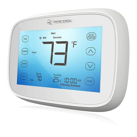
- Page 49 Fig. 24. Thermostat Display...
- Page 50 User Setup Follow these steps to enter the User Setup: Press and hold the key for approximately 3 s econds until the screen changes. Menu number will display at bottom right corner. Press key to cutover to submenu, and press key enter submenu.
- Page 51 Table 3. User Setup Settings. Number Description Settings 0140 S ee MAC and Version 0150 Date and Time Current calendar date and time Display temperature 0 - °F setting (factory setting) 0320 in °F or °C 1 - °C setting 12 - 12-hour clock(factory setting) 0640 Clock Format...
- Page 52 Number Description Settings 0 - Unlocked keypad 0670 Keypad Lockout 1 - Locked keypad -3°F ~ 3°F (°F as temperature format) Temperature Display 0700 -1.5°C ~ 1.5°C (°C as temperature format) Offset 0°F (0°C) (factory setting) 0 - No thermostat reset. 0710 Reset Thermostat 1 - Resets all Installer Setup Options to default values and...
- Page 53 Date/time Setting Consult USER SETUP, choose submenu number 0150 enter date and time setting. Press to switch from date to time in the following order: year, month, day, hour, and minute. Press Fig.25 to adjust the time. (You can advance the time more quickly by holding the key or buttons.)
- Page 54 Setting the fan Press to select fan operation. Press again to select ON or AUTO (toggle to re -select). The selected option blinks. Press to save setting or press to exit without saving changes. Fig.26 ON: Fan is always on. AUTO: Fan runs only when the heating or cooling system is on.
- Page 55 Selecting system mode Press to display options. Press again to select an option. You may need to press two or three times to make a selection—the selected option blinks. Press to save setting Fig.27 or press to exit without saving changes.
- Page 56 Possible system modes: HEAT: Controls only the heating system. COOL: Controls only the cooling system. OFF: Heating/cooling systems are off. AUTO: Selects heating or cooling depending on the indoor temperature. EMER (heat pumps with aux. heat): Controls auxiliary/emergency heat when compressor is locked out. Note: The AUTO and EMER system settings may not ap pear, depending on how your thermostat was installed.
- Page 57 Set Temperature Overrides Lake has two temperature override options: Override Until and Permanent Override. Override Until Holds temperature tempor arily until the next scheduled period time. Press key to adjust temperature you want, the icon Until appears above Time, and the Time becomes next scheduled period time. Press key to exit and confirm the changes, or press to exit without...
- Page 58 Permanent override Keep user settings permanently. Press key once. Screen shows Permanent Hold. Press key to adjust temperature you want. If you want to exit, please press key again.
- Page 59 Cleaning Thermostat Screen The thermostat has touch screen interaction. Follow these steps to clean the screen without making thermostat changes: Press and hold the key for approximately 3 s econds until the screen changes. Th ermostat locks Fig.2 8. out all touch keys for 30 seconds to allow for cleaning.
- Page 60 Screen Locks In User or Installer Setup, menu 0670 allows you to prevent changes to all of the touchscreen functions. In this case, all keys are locked and not functional, the screen displays a lock icon continuously. User setup can also be used to unlock keys and restore the Fig.29.
- Page 61 Setting Filter Reminder Intervals If activated during installation, the filter reminder alerts you by flashing on screen above the time when it is time to repl a ce your filter. Press after changing the filter, to restart the timer. To change the Fig.30 reminder interval: Note:...
- Page 62 Connecting to your Wi-Fi network To complete this process, you must have a smart phone connected to your home wireless network. Please scan the following code to download “MRCOOL Universal” App. iPhone Android If you get stuck... At any point in this procedure, restart the thermostat by removing the thermostat from the wall plate, wait a few seconds, and snap it back onto the wall plate.
- Page 63 1. Please be sure your phone has connected WiFi (don’t connect the hidden internet), download “MRCOOL Universal” . 2. Open App and register. ® Fig. 31. Fig. 32. 3. After login, press top left corner , choose WiFi connection and input the WiFi...
- Page 64 Fig. 33. Fig. 34 4. Press the key on thermostat screen until the “ ” flash. Fig. 35...
- Page 65 5. Now you can press the “connect” on app, app will show processing and after seconds it will show a successful connection. Fig. 36. Fig. 37.
- Page 66 Note: 1. If connected WiFi successfully, it will show on the thermostat, otherwise it will show 2. Each configuration needs to be finished within 5 minutes, otherwise the thermostat will quit configuring.
- Page 67 Leave mode Press the on homepage and the Universal Thermostat will switch to leave mode. (You can set the temperature you need under leave mode. See the following programming to set the temperature.) If the Universal Thermostat has been under leave mode, Fig.
- Page 68 PROGRAMMING Table 4. Schedule Default Program Settings. Set points Schedule Period Time Fan Setting Heat Cool Wake 6:00AM 68°F (20°C) 78°F (26°C) Auto Leave 8:00AM 60°F (16°C) 85°F (29°C) Auto Return 4:00PM 68°F (20°C) 78°F (26°C) Auto Sleep 10:00PM 60°F (16°C) 82°F (28°C) Auto...
- Page 69 Program Heating and Cooling Schedule Your thermostat can control up to four different schedule periods per day: Wake - Period when you awaken and want your home at a comfortable temperature. Leave - Period when you are away from home and want an energy-saving temperature.
- Page 70 Edit Schedule adjust the temperature. Press Press , the screen will to turn to next time period. change. See Fig. 39 and 40. Fig. 40 Fig. 39. In this case, the time will blink, press to adjust the time. Press to turn to next setting.
- Page 71 Repeat the above steps until completin g the setting of four time periods. Then, press to turn to next day, until completing the setting of a week. To end program setting, press key to exit and confirm the program setting, or press to exit without saving changes.
- Page 72 Copy One Day Program After entering a day program you can copy this into another day to save time when creating a weekly program: for example, if you want to copy the program of Monday to Thursday, the methods are as follows: Select the program for Monday , complete the setting of Monday and press , the icon...
- Page 73 Reset Schedule Your thermostat can reset schedule setup option to default setting. Press and hold key for approximately 3 seconds until the screen changes as Fig.41, then release key. Now the setting of schedule resets to default setting as table 4. Fig.
- Page 74 FCC Note Any changes or modifications not expressly approved by the party responsible for compliance could void the user’s authority to operate the equipment. This device complies with part 15 of the FCC Rules. Operation is subject to the following two conditions: (1) This device may not cause harmful interference, and (2) this device must accept any interference received, including interference that may cause undesired operation.
- Page 75 particular installation. If this equipment does cause harmful interference to radio or television reception, which can be determined by turning the equipment off and on, the user is encouraged to try to correct the interference by one or more of the following measures: —Reorient or relocate the receiving antenna.
- Page 76 TROUBLESHOOTING Symptom Possible Cause Action Thermostat is not being No LCD d isplay Check 24VAC between C and R. powered. The upper or lower Check temperature set-points. temperature limits were Check Installer Setup Numbers reached. 0600 or 0610, modify as needed. Temperature settings do not change.
- Page 77 Symptom Possible Cause Action Thermostat minimum Wait up to five minutes for the off-time is activated. system to respond. Sy stem selection is not set Set system selection to correct Heating or cooling to Heat or Cool. position. does not come on. Check Installer Setup Number System type selection is 0170 and make sure correct...
- Page 78 Symptom Possible Cause Action Check wiring. Thermostat is calling Check Installer Setup Number for Heat (Heat on) or Heating or cooling 0170 and make sure correct Cool (Cool on) but no equipment is not operating. system type is chosen. heating or cooling is Verify operation of equipment in running.
- Page 79 Symptom Possible Cause Action Heat pump puts out Changeover Valve is not Set Changeover Valve (Installer configured to match the cool air in the heat Setup Number 0190) to match changeover required by the mode and warm air in the changeover required by the installed heat pump.
- Page 80 Symptom Possible Cause Action Heating equipment is not a Set System Type (Installer Setup Heating equipment is heat pump but System Type Number 0170) to match the running in the cool (Installer Setup Number installed heating and/or cooling mode. 0170) is set to Heat Pump. equipment.
- Page 81 Symptom Possible Cause Action Cannot set the System Type is set to Cool Set System Type (Installer Setup system setting to Only or Heat Only or Heat Number 0170) to match the Heat or Cool. Only with Fan. installed equipment. System is not set to Heat Set the system setting to Heat Heat On is not in the...
- Page 82 Symptom Possible Cause Action Wait up to five minutes for the Compressor minimum off Wait is in the display. cooling or heating (heat pump) timer is active. equipment to turn on. Screen Locked Check Installer Setup Number appears on the The keypad is locked.
Need help?
Do you have a question about the MST03 and is the answer not in the manual?
Questions and answers