Table of Contents
Advertisement
NO. C08443 04204
INSTRUCTION MANUAL
DENYO
DIESEL GENERATING SETS
Before using, be sure to read this manual for the sake of safety.
WARNING
Be sure to observe the items under symbol marks
"
"
CAUTION
and
for the sake of safety.
"
"
Always keep this manual at your machine for the sake of safety.
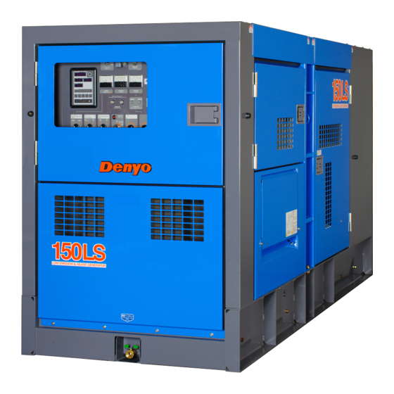
DCA-150LSKE
2-8-5 Nihonbashi-horidomecho, Chuo-ku, Tokyo, 103-8566
Advertisement
Table of Contents

Related Manuals for Denyo DCA-150LSKE


Summary of Contents for Denyo DCA-150LSKE
- Page 1 NO. C08443 04204 INSTRUCTION MANUAL DENYO DIESEL GENERATING SETS Before using, be sure to read this manual for the sake of safety. WARNING Be sure to observe the items under symbol marks " " CAUTION for the sake of safety. "...
- Page 2 Japan...
- Page 3 FOREWORD * Your machine is a portable type diesel generating set. * Do not install, operate or repair this machine without reading this operating manual. * This generator set (machine) must be operated by a person having sufficient knowledge and skill for the sake of safety. Notes on instruction manual * This instruction manual explains correct operation and maintenance of the machine to ensure its performance.
-
Page 4: Table Of Contents
- Contents - 1. Safety Precautions ---------------------------------------------- 1 2. Construction ---------------------------------------------------- 11 2-1 Outline and part names ------------------------------------ 11 2-2 Operating panel, control panel and part names ------------- 13 2-3 Meters ---------------------------------------------------- 14 2-4 Use of switches and controllers --------------------------- 21 3. -
Page 5: Safety Precautions
1. Safety Precautions In order to ensure safe operation, the following symbols are used for explanation of the machine operation. The following symbols, found throughout this manual, alert you to potentially dangerous conditions to the operator, service personnel, or the equipment. ... - Page 6 Safety label Safety labels are attached to the following positions of the machine. * Keep these safety labels clean at all times. * When safety labels are spoiled or lost, contact distributor or our office specifying the nameplate No. shown below and ask for new ones. No.
- Page 7 WARNING ENGINE EXHAUST can kill. ■ Insufficient ventilation may lead to death due to lack of oxygen or poisoning by exhaust gases. * Do not use the machine in a place of poor ventilation or in a place where exhaust gases stays. * Do not use the machine indoors or in storehouse, tunnel, ship hold, tank, etc.
- Page 8 WARNING ELECTRIC SHOCK can kill. ■ Do not touch the output terminals during operation to prevent decease due to electric shock. * Never touch the output terminals during operation. If your hands or the machine are wet, it will result in a death or serious injury.
- Page 9 WARNING ELECTRIC SHOCK by leak can kill. ■ Improper grounding may lead to death due to electric shock. * Be sure to execute the grounding of the machine and the load according to the local rule. ...
- Page 10 WARNING DIESEL FUEL can cause fire or explosion. ■ Fuel and oil are flammable. Incorrect handling results in danger of ignition or fire. * When fuel needs to be supplied to the machine, be sure to stop the engine. Refrain from smoking. Keep the machine away from fire.
- Page 11 WARNING Stacking ■ Improper stacking of machines may cause falling or dropping accidents. When stacking other machines on this machine, be sure to observe the following points. * Check that the bonnet of the machine is free from damage and that the fixing bolts are not loosened and missing.
- Page 12 WARNING BATTERY ■ Battery generates flammable gases. Improper handling may lead to explosion or serious injury. * Battery should be charged in a well ventilated location. Otherwise, flammable gases are accumulated which may be ignited and exploded. * When connecting a booster cable, do not jumper the terminals (+ and -).
- Page 13 CAUTION Operator ■ Do not operate the machine, if operator is tired too much or drinks some alcohol or take some drugs. * Otherwise, it may cause unexpected accidents or injury. ■ During checking or maintenance, be sure to put on suitable clothes and protectors. * Do not put on baggy clothes, necklace, etc., because they are easily caught by projections which may cause injuries.
- Page 14 CAUTION Transportation ■ Do not lift the machine at the support hook or the ladder because it is not strong enough for lifting and may cause a falling accident. * When lifting the machine, use the hanger located at the roof center.
-
Page 15: Construction
2. Construction 2-1 Outline and part names 1. oil drain plug 6. output terminal 2. exhaust gas outlet 7. fuel in 3. hanger rod 8. fuel drain plug 4. support hook 9. control and operating panel 5. coolant in 10. fuel level gauge 11. - Page 16 1. air cleaner 10. fuel tank 2. oil filter 11. battery 3. fuel filter 12. muffler 4. reserve tank 13. fuel pre filter 5. AC generator 14. engine oil in 6. diesel engine 15. blowby drain 7. radiator・inter-cooler 16. environmental base 8.
-
Page 17: Operating Panel, Control Panel And Part Names
2-2 Operating panel, control panel and part names NAME NAME frequency meter engine indicator AC ammeter indicator: engine speed, oil pressure, water AC voltmeter output voltage indication lam temp, battery charging voltage, integrating time frequency change-over switch warning lamps high water temp, low lubricating speed regulator voltage regulator pressure, air element blinding,... - Page 18 environmental base fluid level warning lamp - 14 -...
-
Page 19: Meters
2-3 Meters Engine indicators (1) Engine indicator That indicates the numerical values of engine speed, engine oil pressure, run hours, battery charging voltage, or engine coolant temperature. Indicated Items Unit engine speed ×100kPa engine oil pressure battery charging voltage ℃ engine coolant temperature - 15 -... - Page 20 - 1 - Engine Speed Revolutions per minute is indicated. 1500min is indicated at 50Hz and 1800 min indicated at 60Hz. - 2 - Engine Oil Pressure 2 to 6 × 100 kPa should be indicated at normal engine operation. Higher value would be indicated in cold condition immediately after engine starts.
- Page 21 (3) Alarm and Memory at Abnormal Condition When any abnormal condition occurs in engine oil pressure, battery charging voltage, or engine coolant temperature, the indication will change as the following ; - 1 - The Indicator shows its defect with blinking numbers. - 2 - When the abnormal condition is corrected, the on - and - off indication will stop.
- Page 22 (5) The hour meter has an internal battery The engine monitor incorporates both a rechargeable internal battery as well as a charging circuit. While the generator is not in operation, the engine monitor will still indicate the hours operated via its internal battery. While the generator is in operation, the internal battery recharges.
- Page 23 Generator indicators (1) Frequency meter This meter indicates frequency of the output voltage. Make sure that it indicates 50Hz or 60Hz during operation. (2) AC ammeter This meter indicates AC current flowing into the connected load. Make sure that it is always pointing below the rated current.
- Page 24 Indication/alarm lamp (1) Preheat lamp It has automatically preheating device. If turn the starter switch to "PREHEAT・RUN" position, the preheat lamp will go on according to cooling water (coolant) temperature. When the preheat lamp goes off, it indicates that preheating is completed.
- Page 25 ⑤ High fuel pre filter water level (FUEL FILTER WATER LEVEL) This lamp goes on when the water level in the fuel pre filter would rise. Drain the water in the fuel pre filter soon after the lamp would goes on. (3) Synchronizing lamp When operating in parallel, the synchronizing lamp is used.
-
Page 26: Use Of Switches And Controllers
2-4 Use of switches and controllers Switches (1)Starter switch Functions: ① STOP This switch should be set in this position unless the machine is in operation. The key can be inserted or pulled out in this position. ② PREHEAT / RUN Set the switch in this position until the preheat lamp goes off. - Page 27 (3) Emergency stop button Push this button for emergency stop only. The control circuit will be de-energized and the engine will stop immediately. [Note] Use this button only for emergency stop. After the engine stops, reset the lock by rotating the button to clockwise direction. The engine will not start if the button is still locked.
- Page 28 (6) Panel light switch This is the switch to turn on the panel light. (7) Circuit breaker · 3-phase circuit breaker This is a main switch to supply power to a load. When the load is shorted or in the state of overload, it trips to protect the generator against trouble.
- Page 29 Voltage regulator and overcurrent relay (1) Voltage regulator This regulator is used to control the output voltage. Turn the regulator to clockwise to increase the voltage and counter clockwise to decrease it. Adjust the voltage to the rated voltage with this regulator.
- Page 30 ELECTRONIC GOVERNOR CONTROLLER (ECU Control Panel) This machine is equipped with an electronic governor. The control box contains the Electronic governor controller, adjustment switch, & trimmer. You should not try to adjust the electronic controller for it has already been set in the factory. (1) Isochronous - Droop Change-Over Switch This switch is used to select the control characteristic of the electronic governor.
- Page 31 (3) Defect identify display This is a function that displays engine troubles, and is equipped on the surface of the controller. When the engine starts and the controller turns on, this indicator checks various parameters within about 10 seconds, and if finds normal operation, the digits "00" are displayed. If the indicator finds some parameter abnormality, "E-"...
-
Page 32: Transportation And Installation
3. Transportation and installation 3-1 Transportation of machine CAUTION Transportation ■ Do not lift the machine at the support hook or the ladder because it is not strong enough for lifting and may cause a falling accident. * When lifting the machine, use the hanger located at the roof center. -
Page 33: Installation Of Machine
3-2 Installation of machine WARNING ENGINE EXHAUST can kill. ■ Insufficient ventilation may lead to death due to lack of oxygen or poisoning by exhaust gases. * Do not use the machine in a place of poor ventilation or in a place where exhaust gases stays. - Page 34 Installation procedure * Install the machine horizontally on a solid foundation. * Provide a space of more than about 1.2m at the side of the control panel and fuel feed port to ensure correct operation and supply. * Provide a space of more than about 1.2m on the left and right sides for check of the engine, oil supply and cable connection work.
-
Page 35: Connecting The Load
4. Connecting the load 4-1 Voltage selector switch CAUTION VOLTAGE SELECTOR SWITCH ■ Make sure the Load Circuit System and the Output Terminal Connection are matched. Unmatched connection will cause damage to the load side and the generator. ■... -
Page 36: Cables To Be Used
Cables to be used Selection of cables: Use cables having sufficient size in consideration of the allowable current of the cables and the distance between the machine and the load. If the load current exceeds the allowable current of cables, the cable may be damaged by overheat. -
Page 37: Connecting The Load
4-3 Connecting the load WARNING ELECTRIC SHOCK can kill. ■ Do not touch the output terminals during operation to prevent decease due to electric shock. * When a wiring work is required, be sure to turn OFF the circuit breaker and stop the machine. - Page 38 (1) Fastening the output terminal [Note] In connecting the load, tighten locking bolts securely with a spanner or the like to prevent burning. (2) Connecting three phase output terminal Connect the load to the output terminal after confirmation of load phase and voltage. Use U/V/W for three phase load U...
- Page 39 (3) Precaution in load connection ① Be sure to provide a switch for turning the load ON and OFF between the output terminal block and the load. Note that the use of the breaker of the machine for turning the load ON and OFF may result in breaker failure.
-
Page 40: Grounding
4-4 Grounding WARNING ELECTRIC SHOCK by leak can kill. ■ Improper grounding may lead to death due to electric shock. * Be sure to execute the grounding of the machine and the load according to the local rule. Grounding Execute the grounding certainly to prevent the electric shock by leak. - Page 41 (3) Precaution in grounding ① Select a shady and highly moist place, and burry the grounding rod in such way that its top end is completely hidden in the ground. ② If burying the grounding rod on the place that many pedestrians walk on, clamp the lead wire to prevent catching on it.
-
Page 42: Operation
5. Operation ELECTRONIC GOVERNOR CONTROL Features This machine is equipped with an electronic governor. It is possible to switch to the Isochronous and the Droop control by using the "Isochronous-Droop Change-Over Switch" located in the control box. The governor is set to Droop Control when it is shipped. * Use Droop control for normal operation. - Page 43 Operation Method ①After the engine warms up, set the speed using the Speed Regulator (refer to the right pictured) once the machine is running at high speed. ②Set the required voltage using the voltage regulator. ③Turn ON the Circuit Breaker and the unit will be at power transmission state.
-
Page 44: Checking Prior To Operation
5-1 Checking prior to operation WARNING MOVING PARTS can cause severe injury. ■ t which runs at a high speed is located Rotary uni in the machine. (Note that it is very dangerous if you touch it.) * Be sure to close the door and lock it during operation. - Page 45 (2) Check on engine cooling water (Read the instruction manual for the engine furnished separately.) WARNING HOT COOLANT can cause severe scalds. ■ If the radiator cap is opened while the water temperature is high, steam or hot water will spout out.
- Page 46 (3) Check on fan belt (Read the instruction manual for the engine furnished separately.) ① Check the belt for tension and elongation. Also, check it for damage. Replace if necessary. ② For adjustment or replacement of the belt, refer to the instruction manual for the engine. Press (about 6kg) the position shown by arrow mark (middle of belt) with your thumb.
- Page 47 (5) Check on battery acid CAUTION BATTERY ■ The battery acid is dilute sulfuric acid. Improper handling will cause unexpected burns. * When the battery acid gets on your clothes or skin, wash it out with a large volume of water immediately.
- Page 48 (7) Check grounding for electric shock protection Make sure that the case grounding of the machine and the load are certainly. Do not ground directly 「O」terminal. (8) Check for leak of water and oil Check the machine for the trace of leak of oil or water. If a leak is found, check the location of leak and stop it.
-
Page 49: Startup
5-2 Startup Following is flow of startup. check emergency stop button is reset. circuit breaker:OFF Frequency change-over switch::50or60Hz Speed change-over switch:START/IDLING Single-parallel change-over switch:SINGLE starter switch:PREHEAT/RUN preheat lamp:check preheat lamp goes off. starter switch:START engine startup starter switch:PREHEAT/RUN When it is cold. warm up operation:... - Page 50 CAUTION * Do not start the engine when the machine and the load circuit breaker are ON, or else, power is supplied to the load at the start of the engine which causes electric shocks or trouble in the load. Startup procedure: (1) check it the emergency stop button is reset.
- Page 51 (8) Set the speed change-over switch to "START/IDLING" position and let the engine idle for about 5 minutes. The engine speed during idling will be 650 min (9) After warming up the engine, set the speed change-over switch to the "RUN" position. Check if the idling speed and the frequency are similar to the specified value in the following table.
-
Page 52: Handling During Operation
5-3 Handling during operation (1) Checking after startup ① Make sure that each meter and lamp are normal. normal : warning lamp is all off ② Make sure that the color of exhaust gases from the engine is normal. Check for unusual noise and vibration. Color of exhaust gases - Colorless or light blue: Normal - Black: Abnormal, incomplete combustion... -
Page 53: Shut Down
5-4 Shut down (1) Turn OFF the circuit breaker of the load. circuit breaker of the load (2) Turn OFF the circuit breaker of the machine. circuit breaker of the machine (3) Set the speed change-over switch in "START/IDLING" position and put the machine in cooling operation cooling operation for about 5 min. -
Page 54: Protection Device
5-5 Protection device Protection devices and emergency stop devices are provided for protection of the machine against trouble during operation. When the running caution lamp lights, stop the engine immediately. Check and remove the cause of trouble. Table of protection device action turn OFF the stop... - Page 55 ※○ When the single-parallel change-over switch is parallel side, device acts. - 51 -...
-
Page 56: Parallel Operation
6. Parallel operation [Note] This section is to explain only the procedures for parallel operation that are different from the general single unit operation. For the same procedures with those for single unit operation, read「4. Connecting the load 」and「5. Operation 」. In the case where the required load capacity exceeds the generator capacity, the parallel operation is useful by paralleling electrically generators of 2 units or more. -
Page 57: Parallel Operation
6-2 Parallel operation (1) Turn off the breakers on the load side. (2) Start engine and keep it in warming up. (3) Equalize all the voltages and frequencies on the units by adjusting the voltage regulator and the speed regulator. (4) First turn on the circuit breaker on the No.1 generating set. - Page 58 (8) If more than 2 generators (No.3, No.4~) are required, apply the same ⑤⑥⑦ procedures. (9) Turn on the breakers on the load side. If each AC ammeters show an imbalance in loading, make it in equal loading by adjusting the speed regulator for engine rpm.
-
Page 59: Precautions
6-3 Precautions (1) Keep each generating sets in equal load sharing by adjusting the speed regulator for engine rpm. The set is to undertake more load sharing when the engine rpm. is adjusted higher, while less sharing when adjusted lower. (2) Keep the single-parallel change-over switch in the position "PARALLEL"... -
Page 60: Lubrication, Cooling Water And Fuel
7. Lubrication, cooling water and fuel 7-1 Engine oil Use specified engine oil, otherwise, it greatly affects the startup operation and life of the engine. (1) Type of engine oil Use API service category class CF-4, CH-4, CI-4 or JASO DH-1. [Note] * For new oil, the Total Base Number (TBN) must be at least 8mgkOH/g. - Page 61 (2) Oil viscosity Recommended oil viscosity is SAE 10W-30, all-season type. Use oil according to ambient temperature referring to the table below. Ambient temperature (℃) SAE20 SAE30 SAE5W-20 SAE10W-30 SAE15W-40 [Note]: Do not mix with different kind of oil, or else, it deteriorates the oil quality. (3) Quantity of replacement oil 24.8L...
-
Page 62: Cooling Water
7-2 Cooling water (1) Water for cooling Use the mixture of the good quality soft water and the Long Life Coolant (LLC) of anti-freeze and anti-rust for the radiator. Percentage of LLC must be 30% to 50%, Under the 30%, the anti-rust effect will decrease, and over the 50%, the anti-freeze effect will decease. -
Page 63: Handling Of Battery
8. Handling of battery WARNING BATTERY ■ Battery generates flammable gases. Improper handling may lead to explosion or serious injury. * Battery should be charged in a well ventilated location. Otherwise, flammable gases are accumulated which may be ignited and exploded. * When connecting a booster cable, do not jumper the terminals (+ and -). -
Page 64: Caution On Battery Charge
8-1 Caution on battery charge Charging of loaded battery * Disconnect the wiring cable from the battery terminals before charging. (Otherwise, the alternator may be damaged due to unusual voltage applied to the alternator) * When disconnecting the wiring cables from the battery terminals, remove the ground cable first. -
Page 65: Connection Of Booster Cable, And Installation
8-2 Connection of booster cable, and installation When the engine is started using booster cables, connect the cables as follows. (1) Connection of booster cable ① Connect the clip of the booster cable "A" to the terminal "+" of the machine in trouble. ②... -
Page 66: Periodical Checking And Maintenance
9. Periodical checking and maintenance (Read the instruction manual for the engine furnished separately) WARNING MOVING PARTS can cause severe injury. ■ Rotary unit which moving parts at a high speed is located in the machine. Care should be taken during operation. - Page 67 WARNING HOT PARTS can burn skin. ■ High temperature parts are located in the machine. Care should be taken during operation. * When the machine needs inspection or maintenance, be sure to stop it in advance. * Even after the machine stops, the inside of the bonnet is still hot.
- Page 68 CAUTION Sign for maintenance * During checking or maintenance, be sure to put up a sign "Under maintenance" at a conspicuous place such as the starter switch to prevent the machine from being operated by other persons. ...
-
Page 69: Maintenance Schedule
9-1 Maintenance schedule 50 hours: Checking/First 50 hours * Cleaning on nylon and rubber hose 100 hours: Checking/every 100 hours * Checking on nylon and rubber hose 125 hours: Checking/first 125 hours * Replacement of engine oil * Replacement of engine oil filter cartridge 250 hours: Checking/every 250 hours * Replacement of engine oil (for CF-4 engine oil) * Replacement of engine oil filter cartridge... -
Page 70: Checking/First 125 Hours
9-2 Checking/first 50 hours (1) Checking on nylon and rubber hose Check on the nylon and rubber hose, whether they are hardened or deteriorate. Contact distributor or our office to replace the nylon hose and rubber hose, if necessary. 9-3 Checking/every 100 hours (1) Checking on nylon and rubber hose Check on the nylon and rubber hose, whether they are hardened or deteriorate. - Page 71 ③ After the element is replaced, run the engine for a while. Then, check to see that oil is supplied to the level between H and L. Parts number of oil filter cartridge : Model name Parts number manufacture Parts number of manufact DCA-150LSK Y06020 41209 KOMATSU...
-
Page 72: Checking/Every 250 Hours
9-5 Checking/every 250 hours (1) Replacement of engine oil (for CF-4 engine oil) Replacement is refer to 「9-4.(1) Replacement of engine oil」. * If CH-4・CI-4・JASO DH-1 engine oil is used, replace the engine oil every 500 hours. (2) Replacement of engine oil filter cartridge (for CF-4 engine oil) Replacement is refer to 「9-4.(2) Replacement of engine oil filter cartridge」. - Page 73 (4) Measurement of insulation resistance. WARNING ELECTRIC SHOCK can kill. * Measurement should be made after the machine stops. - Using a 500V insulation resistance tester, make a check once a month to ensure that the insulation resistance is more than 1MΩ. In case of measuring with an insulation resistance tester over 500 V, disconnect all connectors from the AVR located in the control box before measuring.
- Page 74 (5) Check on battery specific gravity. If battery is likely to be discharged due to failure in startup of the engine, measure the specific gravity of battery acid. The relation between battery charge condition (charging rate) and specific gravity is as shown below.
-
Page 75: Checking/Every 500 Hours
(7) Maintenance of output voltage selector switch. CAUTION No output change during running * The generator will fail, if the output voltage is changed during running. Stop the engine before changing the output voltage. 200V class 400V class When the handle of switch hasn`t operated for long term, contact failure of switch terminals may rarely occurs by the dust. - Page 76 ③ Clean the filter housing and, next, pour fuel into the filter with the cap (D) being left installed on the new cartridge (B). After filling the filter with fuel, remove and dispose the cap(D). During the fitting process, spread engine oil lightly on the surface of the cartridge's packing and install it in the filter housing.
- Page 77 Check for main and sub circuit, whether there are no abnormality such as loosening, corrosion and burning, etc. - 73 -...
-
Page 78: Checking/Every 1000 Hours
9-7 Checking/every 1000 hours Checking/every 100, 250 and 500 hours is also required. (1) Replacement of fuel filter cartridge. ① Remove the cartridge type element (cartridge) using filter wrench. ② Clean the filter base. Coat the packing of new cartridge with engine oil thin. Then, mount the cartridge. - Page 79 [Note] Remove the drain to a container and dispose the drain appropriately as Industrial Waste. ・Confirm there is no leakage after it cleans it in an environmental base. Ask the nearest office or service factory when you discover the leakage by any chance.
- Page 80 Model name Parts number manufacture Parts number of manufactu DCA-150LSK Y06020 4665 KOMATSU 600-185-4100 (5) Checking on rubber suspension Check on the rubber suspension, whether it is damaged or deformed by the oil. Contact distributor or our office to replace the rubber suspension, if necessary. (6) Checking on lining Check on the lining, whether it deteriorates greatly, or it is stained by clinging of oilier the like, or it is removed.
-
Page 81: Table Of Periodical Maintenance And Checking
9-8 Table of periodical maintenance and checking ◇:Check or Clean ○:Replacement ☆:Only first time List of maintenance and inspection daily first every every every every every 125h 250h 500h 100h 1000h ◇ Checking on oil level and stain of oil ◇... - Page 82 daily first every every every every every List of maintenance and inspection 125h 250h 500h 100h 1000h ◇ Checking on rubber suspension ◇ Checking on lining ◇ Checking on generator case grounding ◇ Checking on insulation resistance Checking on terminal and connected ◇...
-
Page 83: Troubleshooting
10. Troubleshooting WARNING MOVING PARTS can cause severe injury. ■ Rotary unit which moving parts at a high speed is located in the machine. Care should be taken during operation. * When the machine needs checking or maintenance, be sure to stop it in advance. - Page 84 WARNING HOT PARTS can burn skin. ■ High temperature parts are located in the machine. Care should be taken during operation. * When the machine needs inspection or maintenance, be sure to stop it in advance. * Even after the machine stops, the inside of the bonnet is still hot.
- Page 85 Phenomenon Assumed cause Action Charge or Discharged battery replace Detached or loosened or corroded Cell motor Repair battery terminal will not run Fuse blow Replace or revolution Engine will speed is low Improper starter switch Replace not start u Improper starter Replace Broken lead wire Repair...
- Page 86 Phenomenon Assumed cause Action Voltmeter failure Replace AVR failure Contact Voltage goes too high distributor or VR failure our office Burned rotary rectifier Contact distributor or AVR failure Applied load causes load our office Burned main field, exciter field voltage drop wiring Unbalanced load Balance...
- Page 87 Engine Diagnostic Users can check the engine defect with defect identify display inside the control box. In normal condition When the switch is on, the program number will appear on the display, follows by saved defect code with it’s contents and after a few seconds, if there is no defect, [00] will appear. display example Power ON →...
- Page 88 Defect code list De f e c t Op e n c i r c ui t De f e c t c o n t en t Ma c h i n e c o nd i t i o n Sy st e m r e sp o n c e c o d e e r r o r...
- Page 89 De f e c t Op e n c i r c ui t De f e c t c o n t en t Ma c h i n e c o nd i t i o n Sy st e m r e sp o n c e c o d e e r r o r サ...
- Page 90 De f e c t Op e n c i r c ui t De f e c t c o n t en t Ma c h i n e c o nd i t i o n Sy st e m r e sp o n c e c o d e e r r o r 定...
-
Page 91: Long-Term Storage
11. Long-term storage When the machine is to be stored for a long period of time, choose a cool place free from moisture and dust, and observe the following points. (1) Remove dirt clinged the machine and clean it thoroughly. If painting is peeled off, it should be repaired. -
Page 92: Service Data
12. Service data 12-1 Specifications DCA-150LSKE MODEL MODEL DB-1651K A FREQUENCY 50 / 60 Hz C RATED OUTPUT G 125 /150 kVA E RATED VOLTAGE 200 /220 V ・ 400 / 440 V N 361 /394 A ・ 180 /197 A RATED CURRENT E... -
Page 93: Outline Drawing
12-2 Outline drawing - 89 -... -
Page 94: Generator Connection Diagram
12-3 Generator connection diagram - 90 -... -
Page 95: Engine Wiring Diagram
12-4 Engine wiring diagram - 91 -... -
Page 96: Controller Wiring Diagram
12-5 Controller wiring diagram - 92 -... -
Page 97: Options Instruction Manual
13. Options instruction manual If equipment the option device to the machine after the purchase is required, contact distributor or our office. If the machine is modified on your own, the warranty of manufacturer will become invalid. 13-1 Earth leakage relay ... - Page 98 The current sensitivity of this relay is 30 mA. Improper handling of the relay may lead to unsafe condition in comparison with that does not use the relay. To ensure further safety, install a leakage relay for each load at the position near the load.
- Page 99 [Note] The installation of a leakage relay on the machine can not become a reason for elimination of the need for the load side grounding. The load side grounding is indispensable for earliest possible detection of any leakage caused in the generator. The absence of such grounding requires any leakage to be detected by current flowing through the human body and is very dangerous because the sensitivity of leakage relay provided on the machine is not sufficient for detection of such current.
-
Page 100: Instruction For Fuel Source Changeover Device
13-2 Instruction for fuel source changeover device (Three-way valve) (1) Description of the device The "Fuel piping selector device" selects the supply of fuel to the engine from the machine loaded fuel tank or directly from the outside machine tank through its change-over valve. - Page 101 - 97 -...
-
Page 102: Single-Phase Output Receptacles
13-3 Single-phase output receptacles (1) Description of the device The output terminal section is equipped with two single-phase output terminals, two receptacles (50/60Hz,100/110V), when the AC voltmeter indicates 200/220V or 400/440V, the single phase output voltage stands at 100/110V. [Note] receptacle can be used up to 1.5/1.65kVA.
Need help?
Do you have a question about the DCA-150LSKE and is the answer not in the manual?
Questions and answers