Table of Contents
Advertisement
Quick Links
Advertisement
Table of Contents

Subscribe to Our Youtube Channel
Related Manuals for HiWeigh K8


Summary of Contents for HiWeigh K8
- Page 1 WEIGHT INDICATOR...
-
Page 3: Before Use
Safety precautions WARNING! ▲ Do not use K8 K9 series weighing terminal in hazardous area! Do not use it within areas classified as hazardous division 1/2 or zone 0/1/2/21/22 because of combustible or explosive atmospheres. ▲ Never immerse it in corrosive chemical liquid. - Page 4 Introduction Thank you for selecting and purchasing our K9 weight indicator, this indicator provides a compact and flexible solution for a variety of weighing needs, especially for the wet working places. INVENTIONS AND DESIGN PATENTED ON17-P31351 & ON17-P20743 Double O-ring for the housing, independent sealed PCB case, transparent PC front housing and touch buttons, all give the highest protection class till IP68 and IP69K, it can be used perfectly in the field of meat, fish process or any other food industry, chemical materials, pharmaceutics.
- Page 5 Index Technical Specifications Model Identification Packing List Connecting Power board I&O board Load cell RS232 Input & Output LCD Display Keypad Parameter setting and calibration Operating method F1 – Scale parameter setting F2 – User functions setting F3 – Display parameters F4 –...
-
Page 6: Technical Specifications
1. Technical Specifications Model K8 | K8S | K9 Enclosure Type PBT | SUS304 | PBT+PC Product Dimension 240x160x110mm 250x170x65mm (K8, K9) (K8S) Shipping Weight 2.8kg | 3.3Kg (K8, K9) (K8S) Accuracy Class III Display Resolution 1/3,000 – 1/30,000 100-240V AC... -
Page 7: Packing List
3. Packing List After the weighing terminal received, please open the box carefully and check the following items included: Indicator S.S bracket with screws Connectors and screws bag Manual 4. Connecting 4.1 POWER BOARD K8Ac, K8SAc and K9Ac with only AC/DC power PCB. K8Dc, K8SDc and K9Dc without AC/DC and DC/DC PCB, DC power connect to I/O board. - Page 8 4.3 LOAD CELL For 6-wires, just connect as the indication on the I/O board: K8, K9 Load Cell +EXC………………Excitation + +SEN………………Sense + +SIG……………… Signal + SHIELD……….….Shield -SIG ……………… Signal – -SEN……………… Sense – -EXC……………… Excitation – For 4-wires, short connect: +EXC and +SEN, –SEN and -EXC.
-
Page 9: Lcd Display
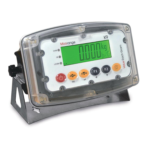
4.5.2 INPUT The terminal has one Input interface, which allows the user to connect with foot pedal or other mechanical switch to control the functions of ZERO, TARE, PRINT, F1 or F2 ( refer to F2.3 Example of connecting to pedal switch 4.5.3 OUTPUT The terminal has 3 output interface, which allows the user to connect with alarming light or other devices. - Page 10 6. Keypad K8 and K8S with membrane keypad, K9 with touch keypad which allows the user to operate it in faster way, even with hand gloves, there are 6 function keys: (keypad example of K9 model) On/Off key Zero key...
-
Page 11: Parameter Setting And Calibration
7. Parameter Setting and Calibration 7.1 Operating Method Keep pressing key for 3 seconds, it will enter the user parameter Setting mode, only F2-F5 available. Open the indicator, and keep pressing CAL switch (SW1) key on the I/O board, it can enter the full parameter Setting (F1-F5) and calibration mode, only authorized technician allows to do this Setting. - Page 12 7.2 F1-F5 Technical Setting F1 – Scale Parameter Setting F1.1 F1.1.1 - Approval mode Non-approval (default) OIML mode NTEP mode F1.1.2 - Full Scale (Capacity) 1 – 999999 (default = 000006) F1.1.3 - Decimal point 0 – 4 (default = 3) F1.1.4 - Division 1, 2, 5, 10, 20, 50...
- Page 13 F1.3 F1.3.1 - Auto Zero Track OFF, 0.5d 1d, 3d for selecting. (default), On OIML mode, 1d and 3d unavailable On NTEP mode, OFF unavailable F1.3.2 - Initial Zero Track OFF, 2%, 10% 20% for selecting. (default), On OIML & NTEP mode, 20% unavailable F1.3.3 - Zero Track by key operation OFF, 2% 10%, 20% for selecting.
- Page 14 F2.2 - F2 Setting (User Function 2) None = none HoLd = Hold function Count = Counting function Ti-da = Time and Date PHoLd = Peak hold function CHEC = Checkweigh function Live Weight Function ACCU = Accumulating function UNIT = Unit Exchange Resolution by 10 times F2.3 -...
- Page 15 F2.9 - OVER backlight selecting (it must be different from F3.3) OFF - no backlight for UNDER RGB - white green Blue RG - yellow RB - magenta GB - cyan F2.10 - Beeper for OVER/UNDER check OFF - no beeping ON - beeping F2.11 -...
- Page 16 F3.2 - Auto Power Off 0 – 10 0 = No auto power off 1-10 = 1 minute to 10 minutes (default of 5min) F3.3 - Backlight Color OFF - no backlight RGB - white green Blue RG - yellow RB - magenta GB -...
- Page 17 F4.2 - COM2 F4.2.1 - Protocol Selection for COM2 SM Continuous Output Format CA Continuous Output Format MT Continuous Output Format AN Continuous Output Format Demand Output (format = 4) MODBUS RTU Key Print Output Stable Output (format = 4) Bluetooth Output (format =4, baud rate=115200) 10 =...
- Page 18 F4.4.4 - New Line Enter Sign Default = 3 F5 – Maintenance F5.1 - Reset to Factory Set Reset Quit On OIML and NTEP mode, Geo factor will not reset to default value F5.2 - Keypad Test The terminal displays PrESS, press the keys from left to right, it will display ON/OFF, ZERO, TARE, UNIT, FUNC, for the last key, it will display PRINT for 1second and then quit.
- Page 19 8. MODBUS Output Format K9 indicator support MODBUS master-slave network communication protocol, has a wealth of switching capabilities, the module, as the slave station, can bi-directionally communicate with the host computer. The following table is K9 address mapping list in MODBUS: Mapping Address Description and Remarks (read only) 40001...
- Page 20 Function Set F2 (bit15~bit8) F1 (bit7~bit0) 0 = NONE 0 = NONE 1 = Hold Function 1 = Hold Function 2 = Count Function 2 = Count Function 40016 3 = Time and Date 3 = Time and Date 4 = Peak Hold Function 4 = Peak Hold Function 5 = Checkweigh Function 5 = Checkweigh Function...
-
Page 21: Main Functions
Mapping Address Description and Remarks (read & write) Communicating calibration, the input weight set to be WT (no decimal point). If WT=0, it’s zero calibration (keep the platform empty before zero calibration) 40070 If Capacity x 1% Capacity, it’s the load weight calibration point, WT is the ≦... - Page 22 Counting Press FN key to enter counting mode, it will display the quantity instead of weight. Press FN key again to quit counting and back to weighing mode Sampling Methods: On counting mode, keep pressing TARE key to enter sampling menu, for AUTO mode, just put the samples and input the quantity.
-
Page 23: Communication Protocols
x10 Resolution Press FN key to enlarge the resolution by 10 times, press FN key again to quit and back to normal weighing mode. Communication Protocols 11.1 SM Continuous Output Format <lf> <s> <r> <n> <m> <f> <xxxxxx.xxx> <uuu> <cr> Where: lf = Line Feed (hex 0A) s = Flags Z = center of Zero,... - Page 24 3. Weight value, could be gross weight or net weight, 6 digits, no sign and decimal point. 4. Tare value, 6 digits, no sign and decimal point. 5. <CR> ASCII return sign (ODH) 6. <CKS> Checksum Status number : A ,B ,C Bits 0 ,1 ,2 Decimal point XXXXX0...
- Page 25 11.4 AN Continuous Output Format S T , + 0 0 0 0 0 . 0 0 _ k g CR LF Four types of headers are available: ST : Stable weight data US : Unstable weight data (including counting data) QT : Stable counting data OL : Out of weighing range The data is always 9 digits including a sign and a decimal point.
- Page 26 F4.4.3 = 2:Flow Weighing Bill WEIGHING REPORT 17/05/2017 10:21:18 ---------------------------- No.0001: 100.1kg G No.0002: 100.1kg N No.0003: 100.1kg N ……… No.0100: 100.1kg G...
Need help?
Do you have a question about the K8 and is the answer not in the manual?
Questions and answers