Table of Contents
Advertisement
Quick Links
Advertisement
Table of Contents

Related Manuals for Olympus SLIDEVIEW VS200


Summary of Contents for Olympus SLIDEVIEW VS200
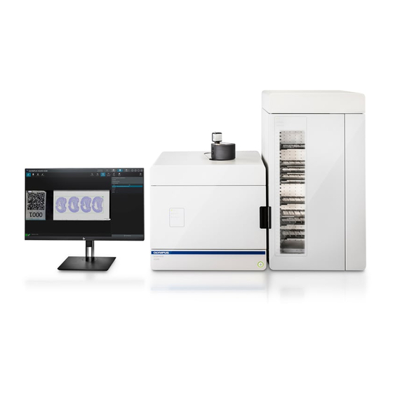
- Page 1 Instructions for use SLIDEVIEW VS200 Optical Microscope and Accessory...
- Page 2 Olympus Soft Imaging Solutions GmbH will from time to time revise the software described in this manual and reserves the right to make such changes without obligation to notify the purchaser.
-
Page 3: Table Of Contents
9.3 VS200 Loader 9.3.1 VS200 Trays 9.3.2 PC and monitor 9.4 VS200 loader transportation locks 9.4.1 Removing transportation lock from VS200 loader’s tray hotel 9.4.2 Removing transportation lock from SCARA robot arm OLYMPUS VS200 System Instructions for use - 3 -... - Page 4 13 Cabling 14 Assembly of the loader housing 14.1 Top panel 14.2 Back panel 14.3 Front panels 15 Verbindung VS200 Scanner und VS200 Loader 15.1 Mechanical Connection VS200 scanner and VS200 loader OLYMPUS VS200 System Instructions for use - 4 -...
- Page 5 19.1 How to insert a tray into the VS200 scanner 19.2 Insert a tray into the VS200 loader 20 Calibrate VS200 using the Olympus Calibration Slide 20.1 Stage limits - Z Axis 20.2 Camera adapter calibration for iDS (VS-264C) camera 20.3 Camera-To-Stage Rotation...
- Page 6 26.3 RoHS Conformity (Europe) 26.4 FCC conformity (USA) 26.5 For Korea only 26.6 China RoHS conformity (China) 26.7 RFID 26.7.1 RFID (Korea) 26.7.2 RFID (USA) 26.7.3 RFID (Canada) 26.7.4 RFID (Taiwan) 27 Support OLYMPUS VS200 System Instructions for use - 6 -...
-
Page 7: About This Manual
In addition, this manual describes how to unbox and install the system as well as how to install further components. These tasks must expressly only be performed by Olympus. As a user you are not allowed to unbox or install the VS200 system by your- self! -
Page 8: Other Applicable Documents
Familiarize yourself with all of the other manuals for the components of the system. Take special note of the safety instructions they contain. Symbols in this documentation Tools required for performing the steps Preconditions for the subsequent steps OLYMPUS VS200 System Instructions for use - 8 -... -
Page 9: Safety
Hands and fingers can get crushed. Sobald das System mit der Stromversorgung verbunden ist, Haare, Finger, Hände und andere Körperteile sowie Kleidung und Gegenstände aus dem Inneren des VS200 Systems fernhalten. OLYMPUS VS200 System Instructions for use - 9 -... -
Page 10: General Safety Instructions
1. Item caution for use 2. Installation prevent from strong vibrations and risk of explosion 3. Temperature prevent from direct sunlight or strong heat sources 4. Humidity prevent from splash water and moisture OLYMPUS VS200 System Instructions for use - 10 -... - Page 11 "over- loading" the sample with excitation light. OLYMPUS VS200 System Instructions for use - 11 -...
- Page 12 If anti-virus software is running while you are acquiring images, it can lead to the loss of individual acquisitions. It can also slow down the acquisition pro- cess or even cause it to be aborted altogether. OLYMPUS VS200 System Instructions for use - 12 -...
-
Page 13: Safety Instructions For The Laser
VS200 system. This will minimize the risk of exposure to the UV light. If the light source has a malfunction please contact Olympus or Excelitas cus- tomer support. If the light source is serviced always make sure that the power cord is disconnected. -
Page 14: Hinweise Zum Aufstellen
The devices must only be moved using the designated handles to avoid dam- ages on the device and personal injuries. The system should not be repositioned by the end user. If the system has to be repositioned an Olympus sales representative has to be contacted first. Betriebs- und Lagerbedingungen Positioning the system... - Page 15 The maximum permissible relative humidity range for storage is 10% to 95%. The maximum permissible temperature change rate for storage is 30°C/h. The maximum permissible atmospheric pressure for storage is 70 to 106 kPa. OLYMPUS VS200 System Instructions for use - 15 -...
-
Page 16: Tools And Accessories
4 Tools and accessories Tools and accessories 2,5 mm, 3 mm with ball end, 4 mm, 5 mm hex keys OLYMPUS VS200 System Instructions for use - 16 -... -
Page 17: Scope Of Supply
Additional box Power supply (not available in all countries) Optional hardware VS200 loader Pallet VS200 loader Housing panel back Housing panel top Housing back panel cover 4 1x4 inch tray Instruction manual OLYMPUS VS200 System Instructions for use - 17 -... - Page 18 The Fluorescence kit C is not available in all countries. IX3-RFACA IX3-RFALFE UPFLN4x U-FF filter cube 2x Black-out filter 1x Glas filter U-FFWO T3 X-Cite Turbo Fluorescence kit D The Fluorescence kit D is not available in all countries. OLYMPUS VS200 System Instructions for use - 18 -...
- Page 19 5 Scope of supply IX3-RFACA IX3-RFALFE UPFLN4x U-FF filter cube TV1XC X-Cite Turbo OLYMPUS VS200 System Instructions for use - 19 -...
-
Page 20: System Diagram
Filter sets and cameras are not part of the configuration. Remark: Configuration C and D are not available in all countries. Basic configuration Component IX3-RFACA IX3-RFALFE UPFLN4X object- U-FF, filter cube (empty) Individual components OLYMPUS VS200 System Instructions for use - 20 -... - Page 21 Optional - Filter sets Component Recommended single-band single-band single-band multi-band emit- filter set exciter exciter exciter multi-band emit- single-band emit- single-band emit- Monochrome cameras Component VS304M Orca Flash 4.0 ORCA Fusion VS200 OLYMPUS VS200 System Instructions for use - 21 -...
-
Page 22: Trays
VS200 MTL (Multi Tray Loader) system. By default every VS200 sys- tem is equipped with at least one tray for 6 1x3 inch slides (76 × 26 mm, DIN ISO 8037- OLYMPUS VS200 System Instructions for use - 22 -... - Page 23 7 Trays Additional tray types 3 slides in 2x3 inch (76 x 52 1 slide in 3x4 inch (76,3 x 10³ 1 slide in 4x5 inch (76,3 Add image x 128 mm) OLYMPUS VS200 System Instructions for use - 23 -...
-
Page 24: Specifications
Turbo, X-Cite Xylis) Camera sys- Brightfield 2/3” CMOS camera, 3.45 µm x 3.45 µm pixel size, high sensitivity, high resolution Fluorescence Olympus VS304 high sensitive, high resolution or Hamamatsu ORCA Flash4.0 V3 and Orca Fusion OLYMPUS VS200 System Instructions for use - 24 -... - Page 25 Temperature: 15 – 28 degree centigrade, humid- ity: 30 % – 80 % (non condensing) Power Power Consumption Power Supply Input 100-240 VAC; 50/60 Hz; 4 A Ratings Output 24VDC, 9,2 A, 221 W MAX. OLYMPUS VS200 System Instructions for use - 25 -...
-
Page 26: Unboxing
9 Unboxing Unboxing The units described below must be assembled and adjusted by Olympus. If these units are assembled or adjusted by the customer, the operations are not ensured. VS200 Scanner The units described below must be assembled and adjusted by Olympus. If these units are assembled or adjusted by the customer, the operations are not ensured. -
Page 27: Removing Transportation Lock From Stage
Demontieren Sie vor Inbetriebnahme des Scanners unbedingt alle Trans- portsicherungen! 9.2.1 Removing transportation lock from stage The units described below must be assembled and adjusted by Olympus. If these units are assembled or adjusted by the customer, the operations are not ensured. Hex screwdriver (size 2.5 mm) 1. -
Page 28: Removing Transportation Lock From Transmitted Light Condenser (Bx3-Ucd8A)
View from below 9.2.2 Removing transportation lock from transmitted light condenser (BX3-UCD8A) The units described below must be assembled and adjusted by Olympus. If these units are assembled or adjusted by the customer, the operations are not ensured. ATTENTION The transportation locks must be remounted each time before the unit is trans- ported. - Page 29 2. Remove the transportation lock from the transmitted light condenser. To do so, remove the 2 hex screws (size 3) indicated in the figure. 3. Pull the transportation lock forwards and down to remove it. OLYMPUS VS200 System Instructions for use - 29 -...
-
Page 30: Vs200 Loader
9 Unboxing VS200 Loader The units described below must be assembled and adjusted by Olympus. If these units are assembled or adjusted by the customer, the operations are not ensured. CAUTION Risk of injury and risk of device damage if components are dropped The loader or other components might drop when you are moving them. - Page 31 10. Remove the tape at the bottom left corner and take out the bubble foil pocket which contains the cable for the loader connection. 11. Open the door and remove the six desiccant bags. OLYMPUS VS200 System Instructions for use - 31 -...
-
Page 32: Vs200 Trays
2. Put the trays aside for later use. 9.3.2 PC and monitor The units described below must be assembled and adjusted by Olympus. If these units are assembled or adjusted by the customer, the operations are not ensured. 1. Take the PC out of it's cardboard packaging. -
Page 33: Removing Transportation Lock From Vs200 Loader's Tray Hotel
9.4.1 Removing transportation lock from VS200 loader’s tray hotel The units described below must be assembled and adjusted by Olympus. If these units are assembled or adjusted by the customer, the operations are not ensured. OLYMPUS VS200 System... -
Page 34: Removing Transportation Lock From Scara Robot Arm
4 hex screws (size 3 mm) indicated in the figure. 9.4.2 Removing transportation lock from SCARA robot arm The units described below must be assembled and adjusted by Olympus. If these units are assembled or adjusted by the customer, the operations are not ensured. -
Page 35: Removing Transportation Lock From Scara Robot Arm's Coun- Terweight
To do so, loosen the 8 hex screws (size 3 mm) indicated in the figure. 9.4.3 Removing transportation lock from SCARA robot arm’s coun- terweight The units described below must be assembled and adjusted by Olympus. If these units are assembled or adjusted by the customer, the operations are not ensured. OLYMPUS VS200 System... - Page 36 SCARA robot arm. To do this, loosen the 3 hex screws (size 3 mm) indicated in the figure. Make sure that the screws to do not fall inside the housing. The unit of SCARA robot arm and counterweight can now move freely. OLYMPUS VS200 System Instructions for use - 36 -...
-
Page 37: Mounting Of Components
By default a VS200 system is shipped with a 2x and 20x objective. Additionally recommended objectives are the 10x and 40x UPLXAPO. Basically, all other Olympus objectives that fit into the IX3-nosepiece can be used and are supported. 5. Remove the small plastic protection cover from the objective position. -
Page 38: Immersion Objectives
Pay attention to the following notes when using an immersion medium. CAUTION Certain immersion media can contain harmful substances. Make sure to read the manufacturer's safety data sheet before using your immersion medium. OLYMPUS VS200 System Instructions for use - 38 -... -
Page 39: Phase Contrast (Ph) Objectives
Otherwise damage can occur to the liquid dispenser. As the liquid dispenser was tested with Olympus immersion media the best performance will be obtained with Olympus immersion media (Olympus Type-F Immersion Oil or Olympus Silicon Immersion Oil SIL300CS-30SC). -
Page 40: Mounting Fluorescence Components
11 Mounting fluorescence components Mounting fluorescence components The units described below must be assembled and adjusted by Olympus. If these units are assembled or adjusted by the customer, the operations are not ensured. Skip this chapter if you have a brightfield system only. - Page 41 6. Remove the two 3 mm hex socket screws from the left and the right secur- ing brackets from the VS200 system as shown in the image below. OLYMPUS VS200 System Instructions for use - 41 -...
- Page 42 9. Insert the IX3-RFACA/ IX3-RFALFE unit into the system. Make sure that it fits into the rails on the left and the right side and flip down the brackets. OLYMPUS VS200 System Instructions for use - 42 -...
- Page 43 10. Tighten the two 3 mm hex socket screws to fix the brackets. 11. Attach the RFALFE supporting bracket again at the back of the system's frame. Insert the two 4 mm hex socket screws but don't tighten them. OLYMPUS VS200 System Instructions for use - 43 -...
- Page 44 13. Make sure the power is switched off and attach the IX3-RFACA cable to the socket at the back of the IX3-RFACA. 14. Attach the black tamper protection plate again and tighten the six hex socket screws. OLYMPUS VS200 System Instructions for use - 44 -...
-
Page 45: Fluorescence Filter Wheels Or Camera Adapter For Monochrome Camera
11.2 Fluorescence filter wheels or camera adapter for mono- chrome camera The units described below must be assembled and adjusted by Olympus. If these units are assembled or adjusted by the customer, the operations are not ensured. Depending on the customer’s configuration you either have to mount only one or two fast filter wheels. - Page 46 The orientation for Chroma emission filters is with the arrow pointing away from the camera. 1. Attach the U-FFWR to the flange of the IX3-RFALFE at the back of the sys- tem and tighten the two 3 mm headless hex screws. OLYMPUS VS200 System Instructions for use - 46 -...
-
Page 47: Add Or Replace Filter (U-Ffwr)
2. Remove the backside top panel. See Top panel auf Seite 3. To add or replace a 25mm emission filter in the U-FFWR open the cover of the filter wheel loosening the knurled head screw. OLYMPUS VS200 System Instructions for use - 47 -... - Page 48 8. At the top right, on the menu bar click the [Manual control] button. 9. Select the [Acquire] > [Devices] > [Device Settings] command to open the [Device Settings] dialog box. OLYMPUS VS200 System Instructions for use - 48 -...
-
Page 49: U-Ffwo T3 (Motorized Fast Observation Filter Wheel)
Device settings - filter auf Seite 11.2.3 U-FFWO T3 (Motorized fast observation filter wheel) The units described below must be assembled and adjusted by Olympus. If these units are assembled or adjusted by the customer, the operations are not ensured. - Page 50 Filters] for more information about filter insertion. 3. Mount the U-FFWO T3 with the cable connector facing to the left side onto the beam splitter and tighten the headless hex screw (3.0 mm) facing towards the front. OLYMPUS VS200 System Instructions for use - 50 -...
-
Page 51: Add Or Replace Filter (U-Ffwo)
2. To add or replace a 25 mm emission filter in the U-FFWO, open the cover of the filter wheel using a 3 mm hex key. 3. Insert the filter into an empty position. Make sure that you orient the filter correctly when you insert it. OLYMPUS VS200 System Instructions for use - 51 -... -
Page 52: Tv 1.0X Adapter
Device settings - filter auf Seite 11.2.5 TV 1.0x adapter The units described below must be assembled and adjusted by Olympus. If these units are assembled or adjusted by the customer, the operations are not ensured. 1. In case you have a TV1.0x adapter mount it onto the beam splitter and tighten the headless hex screw (3.0 mm) which is facing towards the front. -
Page 53: Orientation Of The Monochrome Camera
11.3.1 Orientation of the monochrome camera The units described below must be assembled and adjusted by Olympus. If these units are assembled or adjusted by the customer, the operations are not ensured. The orientation of the monochrome camera is very important! The orientation of the VS304M camera should be with the iDS logo to the front (angled USB-C cable port to the back). - Page 54 The counternut should be 1 turn away from the C-mount adapter. C-mount adapter counternut short side long side 2. Hand-tighten the short side of the C-mount adapter to the camera clock- wise. OLYMPUS VS200 System Instructions for use - 54 -...
- Page 55 4. Hand-tighten the camera and C-mount adapter to the U-FFWO. Be aware to tighten the camera orientation lock first to prevent slippage of the locking mechansism. To do so, tighten the rota- tion locking screw using a 2 mm hex key. OLYMPUS VS200 System Instructions for use - 55 -...
-
Page 56: X-Cite Adapter
Camera adapter auf Seite 139. 11.4 X-Cite adapter The units described below must be assembled and adjusted by Olympus. If these units are assembled or adjusted by the customer, the operations are not ensured. Hex key (3.0 mm) X-Cite adapter OLYMPUS VS200 System... -
Page 57: Objective
11.6 LED light source The units described below must be assembled and adjusted by Olympus. If these units are assembled or adjusted by the customer, the operations are not ensured. Two LED light sources (X-Cite Xylis and X-Cite Turbo) are available for the VS200 sys- tem. -
Page 58: Filter Set
11.7 Filter set The units described below must be assembled and adjusted by Olympus. If these units are assembled or adjusted by the customer, the operations are not ensured. Depending on the purchased filter set insert the single-band excitation filters into the U-FFWR filter wheel. -
Page 59: Add Or Replace Filter Cube (Ix3)
[Previously Used Layout] button at the top right in the nav- igation bar on the software's start page. 7. At the top right, on the menu bar click the [Manual control] button. OLYMPUS VS200 System Instructions for use - 59 -... -
Page 60: U-Fdict Filter Cube
Device settings - filter auf Seite 11.7.3 U-FDICT filter cube The units described below must be assembled and adjusted by Olympus. If these units are assembled or adjusted by the customer, the operations are not ensured. Mount an optional U-FDICT for polarized light acquisition. The U-FDICT should be placed into position 8 of the IX3-RFACA because this position is configured in the default device settings. -
Page 61: X-Cite Turbo
11 Mounting fluorescence components 11.7.4 X-Cite Turbo The units described below must be assembled and adjusted by Olympus. If these units are assembled or adjusted by the customer, the operations are not ensured. The excitation filters in the X-Cite Turbo have to be placed as indicated in the boxes in the picture below (the arrows show the filter orientation). -
Page 62: Assembly Of The Housing For Scanner
12.1 Left panel The units described below must be assembled and adjusted by Olympus. If these units are assembled or adjusted by the customer, the operations are not ensured. Before you install the left side panel make sure that the power switch of the U-CBM is switched on. - Page 63 3. Once the pins are inside the rubber rings push the panel towards the frame and finally push it down so that the black quick lock pins of the side panel fit OLYMPUS VS200 System Instructions for use - 63 -...
-
Page 64: Right Panel
12.2 Right Panel The units described below must be assembled and adjusted by Olympus. If these units are assembled or adjusted by the customer, the operations are not ensured. Depending on your system configuration (with or without loader) the VS200 system comes with two different right side panels. -
Page 65: Back Panel
The three knurled head screws at the top are part of the top panel and are tightened later. 1. Guide the three cables from the backside of the VS200 system through the back panel like shown in the image below. OLYMPUS VS200 System Instructions for use - 65 -... -
Page 66: Top Panel
On each side there is the connector (system side) for the grounding flag. 1. Connect the two grounding flags (left and right side) to the top panel. 2. Put the top panel parallel to the scanner. OLYMPUS VS200 System Instructions for use - 66 -... - Page 67 1. Put the round cover on top of the beam splitter flange and fix it by tight- ening the 3mm headless hex screw. Images Top panel - second part To attach the second part of the top panel follow the instructions below. OLYMPUS VS200 System Instructions for use - 67 -...
- Page 68 2. Open the front door and put the short top panel parallel on the scanner. 3. Gently push it towards the back of the system until the pins fit into the quick lock sockets. OLYMPUS VS200 System Instructions for use - 68 -...
- Page 69 If the top panels are mounted correctly, it should look like this: 5. Connect the two grounding flags to their counter plugs on the right and left side like shown in the image below. Left side Right side OLYMPUS VS200 System Instructions for use - 69 -...
-
Page 70: Cabling
13 Cabling Cabling The units described below must be assembled and adjusted by Olympus. If these units are assembled or adjusted by the customer, the operations are not ensured. The VS200 PC has a label on its backside indicating where to plug in the individual cables. - Page 71 CAN Bus VS200 internal HP LCD screen Display port Bottom of LCD screen HP LCD screen Power cord Bottom of LCD screen Display port HP mouse USB 2.0 HP keyboard USB 2.0 OLYMPUS VS200 System Instructions for use - 71 -...
-
Page 72: Assembly Of The Loader Housing
14 Assembly of the loader housing Assembly of the loader housing The units described below must be assembled and adjusted by Olympus. If these units are assembled or adjusted by the customer, the operations are not ensured. The VS200 loader is shipped with the two side panels already mounted. Follow the order of panel mounting as described in the chapter below. -
Page 73: Front Panels
2. Subsequently tighten all other knurled screws. 14.3 Front panels The units described below must be assembled and adjusted by Olympus. If these units are assembled or adjusted by the customer, the operations are not ensured. 1. Mount the horizontal and vertical front panel as described in the following steps. - Page 74 3. Connect the grounding flag to the vertical panel and push the panel towards the system so that the quick lock sockets of the panel fit onto the quick lock pins of the loader. OLYMPUS VS200 System Instructions for use - 74 -...
-
Page 75: Verbindung Vs200 Scanner Und Vs200 Loader
Verbindung VS200 Scanner und VS200 Loader 15.1 Mechanical Connection VS200 scanner and VS200 loader The units described below must be assembled and adjusted by Olympus. If these units are assembled or adjusted by the customer, the operations are not ensured. - Page 76 7. Tighten the 2 hex screws (size 5 mm) which attach the connector of the VS200 scanner to the VS200 loader. 8. Remove the remaining handles from the VS200 scanner and the VS200 loader. 9. Reconnect the VS200 system to the power supply. OLYMPUS VS200 System Instructions for use - 76 -...
-
Page 77: Pc Operating System Language
If you want to change the language of the operating system follow the instructions below. Japanese and Chinese are pre-installed on the VS200 PC. 1. Open the Windows Settings and select [Time & Language]. 2. Click on the language you would like to use. OLYMPUS VS200 System Instructions for use - 77 -... -
Page 78: Vs200 Asw Software Setup
17 VS200 ASW software setup VS200 ASW software setup The units described below must be assembled and adjusted by Olympus. If these units are assembled or adjusted by the customer, the operations are not ensured. This chapter describes the installation of VS200 ASW on a VS200 system PC. - Page 79 To activate the licences at customer site the PC needs internet access. If no internet access is available the licences can also be activated offline. In this case follow the instruction during the activation process. OLYMPUS VS200 System Instructions for use - 79 -...
- Page 80 7. Change language (English is default). Proceed with [Next]. 8. Change installation location (not recommended). Proceed with [Next]. 9. A change of the temporary file location (D:\Temp) is not recommended. Proceed with [Next]. OLYMPUS VS200 System Instructions for use - 80 -...
- Page 81 ORCA-Flash4.0 or ORCA-Fusion VS200 and proceed with [Next]. 11. Select [Add icon to the desktop] and [Add manuals shortcut to the desktop] and proceed with [Next]. 12. Start setup by clicking [Next]. OLYMPUS VS200 System Instructions for use - 81 -...
- Page 82 13. Finish the setup process by clicking the [Finish] button. 14. In the following dialog box, click the [Close] button and do not install any example data or tools. 15. Turn on the VS200 system. OLYMPUS VS200 System Instructions for use - 82 -...
- Page 83 The initialization process might need up to two minutes. Error messages If you see the error message below once the software is up and running please refer to Troubleshooting auf Seite 179. OLYMPUS VS200 System Instructions for use - 83 -...
- Page 84 If you see the following error message it means that you are using a VS200 loader which is not yet configured in the device list. Refer to chapter VS200 device configuration auf Seite 85 to add the loader to the system configuration. OLYMPUS VS200 System Instructions for use - 84 -...
-
Page 85: Vs200 Device Configuration
Depending on the configuration of your VS200 kit (FL light source, fast filter wheels and filter set) select one of the five. If you have a VS200 brightfield system there is only one (VS200) device configuration available. OLYMPUS VS200 System Instructions for use - 85 -... -
Page 86: Activate The Motorized Polarizer
1. Use the [Acquire] > [Devices] > [Device List] command to open the [Device List] dialog box. 2. Select the [Microscope] tab. 3. Make sure that the check box [VS200 Liquid Dispenser] is selected. OLYMPUS VS200 System Instructions for use - 86 -... -
Page 87: Device Settings - Objectives
2. To add a phase contrast objective select the [Magnification] entry and the correct [Objective Type] entry for e.g. position 5 and add e.g. [PH] in the [Description] field to distinguish between ‘normal’ 20x and ‘PH’ 20x. Beispiel OLYMPUS VS200 System Instructions for use - 87 -... -
Page 88: Device Settings - Filter
Filter type VS200 device IX3 filter cube IX3 Mirror turret 25 mm excitation filter U-FFWR 25 mm emission filter U-FFWO 2. In the [Pos.] options, select the position where you inserted the new filter. OLYMPUS VS200 System Instructions for use - 88 -... -
Page 89: Manual Device Configuration
Customization] dialog box to be able to use the new filter. See Create or adjust an observation method auf Seite 18.5 Manual device configuration This chapter describes the manual configuration of VS200 hardware devices. OLYMPUS VS200 System Instructions for use - 89 -... -
Page 90: Orca Monochrome Camera
In the [Device Customization] dialog box you can make changes to existing obser- vations methods. For example, you can add a different monochrome camera or you can add new observation methods. OLYMPUS VS200 System Instructions for use - 90 -... -
Page 91: Orca Camera Adjustments
4. In the [Status] picklist, set the Orca camera to the status [Use]. 5. In the [Image type] picklist, change the [Current] entry to the [16-bit gray- scale] entry. 6. Do this for all other mono camera-related observation methods. OLYMPUS VS200 System Instructions for use - 91 -... -
Page 92: Setup Phase Contrast (Ph) Observation Method
4. Type in a name, e.g. "Phase Contrast". 5. In the [Type] picklist select [Phase Contrast]. 6. Select the [BX3 Condenser] entry from the available components and choose the [Adjust per objective] entry in the [Status] pick list. OLYMPUS VS200 System Instructions for use - 92 -... - Page 93 [Top Lens] > [In] option for the 20x PH objective. Refer to chapter VS200 LED lamp voltages auf Seite 97 for the correct lamp voltages for phase contrast acquisition. OLYMPUS VS200 System Instructions for use - 93 -...
-
Page 94: Setup Polarization (Pol) Observation Method
[IX3 Mirror Turret] entry from the available components and choose the [Adjust] entry in the [Status] pick list. 7. In the [All objectives] tab select the [U-FDICT] analyzer for all objectives. OLYMPUS VS200 System Instructions for use - 94 -... -
Page 95: Create Or Adjust An Observation Method
2. At the top right, on the menu bar click the [Manual control] button. 3. Use the [Acquire] > [Devices] > [Device Settings] command to open the [Device Settings] dialog box. OLYMPUS VS200 System Instructions for use - 95 -... - Page 96 IX3 filter cube in the IX3 Mirror Turret. 10. Click [OK] to save the changes. 11. As you created a new observation method you now have to carry out the OLYMPUS VS200 System Instructions for use - 96 -...
-
Page 97: Vs200 Led Lamp Voltages
2x PLN not defined not defined 4x UPLFLN not defined 10x UPlanXApo 20x UPlanXApo not defined 40x UPlanXApo not defined 40xUplanXApoS not defined 60x UPlanXApoO not defined 100x UPlanXApoO not defined OLYMPUS VS200 System Instructions for use - 97 -... -
Page 98: Vs-304M Voltages (%)
(AS max) (AS 75%) 2x PLN not defined 4x UPLFLN 10x UPlanXApo 20x UPLXAPO not defined 40x UPLXAPO not defined 40x UPlanXApoS not defined 60x UPLXAPO not defined 100x UPLXAPO not defined OLYMPUS VS200 System Instructions for use - 98 -... -
Page 99: How To Insert A Slide Into A Tray
2. Insert the tray horizontally following the orientation which is printed on the tray: [Insert this way] into the rails and push it inside (about 6cm) until you cannot push it any further. OLYMPUS VS200 System Instructions for use - 99 -... -
Page 100: Insert A Tray Into The Vs200 Loader
[Select Slide for Calibration] on the start page of the software to select a slide and tray for calibration or select any scan mode to select and load a tray into the scanner. OLYMPUS VS200 System Instructions for use - 100 -... -
Page 101: Calibrate Vs200 Using The Olympus Calibration Slide
The VS200 ASW software offers a dedicated calibration wizard for all necessary cal- ibrations. The image shows the [Calibrations] dialog box. In order to get optimal results, we recommend using the VS Olympus Calibration Slide v2.0 to calibrate the system. Layout of the Calibration Slide (Version 2.0) The image shows the layout of the VS Olympus Calibration Slide v2.0. - Page 102 20 Calibrate VS200 using the Olympus Calibration Slide 1. Insert the VS-calibration slide into position 3 of the slide tray. 2. Click the [Exchange Trays] button on the start page of the VS200 ASW soft- ware to insert the tray.
-
Page 103: Stage Limits - Z Axis
20 Calibrate VS200 using the Olympus Calibration Slide 20.1 Stage limits - Z Axis The X and Y axes do not have to be calibrated again. However, the Z axis calibration is dependent on the glass slide thickness. Therefore it is neces- sary to calibrate the Z axis. - Page 104 20 Calibrate VS200 using the Olympus Calibration Slide 3. Select the Axis] check box and continue with [Next]. 4. At the top right in the menu bar click the [Manual control] entry to switch the layout. 5. In the [Manual Control] layout, change to the 20x objective.
- Page 105 20 Calibrate VS200 using the Olympus Calibration Slide 10. Click the [Finish] button to finalize the calibration process. OLYMPUS VS200 System Instructions for use - 105 -...
Need help?
Do you have a question about the SLIDEVIEW VS200 and is the answer not in the manual?
Questions and answers