
Related Manuals for U-Line UOCL115


Summary of Contents for U-Line UOCL115
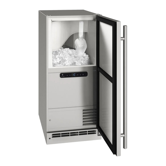
- Page 1 USER GUIDE & SERVICE MANUAL Outdoor Collection UOCL115 / UOCP115 15” Clear Ice Maker ● ●...
-
Page 2: Table Of Contents
USER GUIDE & SERVICE MANUAL u-line.com Table of Contents Intro Wire Diagram Product Liability Safety Warranty Claims Safety and Warning Parts Disposal And Recycling Ordering Replacement Parts System Diagnosis Guide Installation Compressor Specifications Environmental Requirements Troubleshooting Extended Electrical Control Operation - Service Cutout &... - Page 3 ® to preserve the right product, in the right place, at the right temperature. Since 2014, U-Line has been part of the Middleby family of brands. All products are designed, engineered, and assembled in Milwaukee, Wisconsin, USA, and select products are available worldwide.
-
Page 4: Safety And Warning
USER GUIDE u-line.com Safety and Warning WARNING NOTICE CALIFORNIA PROPOSITION 65 Please read all instructions before installing, This product contains chemicals known to the operating, or servicing the appliance. state of California to cause cancer and birth defects or other reproductive harm. -
Page 5: Disposal And Recycling
USER GUIDE u-line.com Disposal and Recycling DANGER RISK OF CHILD ENTRAPMENT. Before you throw away your old refrigerator or freezer, take off the doors and leave shelves in place so children may not easily climb inside. If the unit is being removed from service for disposal,... -
Page 6: Environmental Requirements
USER GUIDE u-line.com Environmental Requirements This unit is designed to operate between 50°F (10°C) and 100°F (38°C). Higher ambient temperatures may reduce the unit’s ability to reach low temperatures and/or reduce ice production on applicable models. For best performance, keep the unit out of direct sunlight and away from heat generating equipment. -
Page 7: Electrical
USER GUIDE u-line.com Electrical WARNING SHOCK HAZARD — Electrical Grounding Required. Never attempt to repair or perform maintenance on the unit until the electricity has been disconnected. Never remove the round grounding prong from the plug and never use a two-prong grounding adapter. -
Page 8: Cutout & Product Dimensions
14 15⁄16” (379 mm) PREPARE SITE Your U-Line product has been designed for either free- standing or built-in installation. When built-in, your unit does not require additional air space for top, sides, or rear. However, the front grille must NOT be obstructed, FRONT 28”... -
Page 9: Side By Side Installation
USER GUIDE u-line.com Side-by-Side Installation 3. Place bracket over holes and attach to unit with two screws removed in step 2 using a T-25 Torx driver. Two units may be installed side-by-side. Tighten screws fully. Cutout width for a side-by-side installation is the cutout 4. -
Page 10: Water Hookup
Plastic may crack compression fitting. or rupture with age and cause damage to your U-Line recommends using accessory water hookup kit - home. Part # 80-54674-00. The kit includes a 10’ (3 m) braided flexible water supply line and a brass hose fitting. - Page 11 USER GUIDE u-line.com 3. Locate water 8. Install retaining clip. valve in the front of the unit and thread water supply line through. NOTICE Route the water supply line through the unit so it does not come into contact with any internal components other than the solenoid valve.
-
Page 12: Drain
DRAIN CONNECTION CAUTION With Trap and Vent Proper Drain If your U-Line unit did not come with a factory installed drain pump you must use a gravity A gravity drain may be used if: style drain connection. For assistance in Drain line has at least a 1”... - Page 13 Air Gap (Optional Hook-Up) requirements for a gravity drain, you may have ordered a pre-installed U-Line P60 drain pump. Waste If you need to install a P60 drain pump into your unit, see Shut-Off...
-
Page 14: Anti-Tip Bracket
USER GUIDE u-line.com Anti-Tip Bracket Slide unit out so screws on top of unit are easily accessible. Remove the two screws from the opposite side of the hinge assembly using a T-25 Torx driver (see below). Place bracket over holes and attach to unit with two screws removed in step 2 using a T-25 Torx driver. -
Page 15: General Installation
USER GUIDE u-line.com General Installation INSTALLATION Plug in the power/electrical cord. LEVELING INFORMATION Gently push the unit into position. Be careful not Use a level to to entangle the cord or water and drain lines, if confirm the unit is applicable. -
Page 16: Grille Installation
USER GUIDE u-line.com Grille Installation REMOVING AND INSTALLING GRILLE WARNING Disconnect electric power to the unit before removing the grille. When using the unit, the grille must be installed. Removing the grille 1. Disconnect power to the unit. 2. Remove three screws (1). -
Page 17: Door Swing
USER GUIDE u-line.com Door Swing Wall 2-1/8" Min. (54 mm) 90° Door Swing Units have a zero clearance for the door to open 90°, when installed adjacent to cabinets. Stainless Steel models require 2-1/8" (54 mm) door clearance to accommodate the handle if installed next to a wall. -
Page 18: Door Adjust
USER GUIDE u-line.com Door Adjustments 3. Align door squarely with cabinet. 4. Make sure gasket is firmly in contact with cabinet all HINGE COVER the way around the door (no gaps). The hinge cover included with the literature bag is optional. - Page 19 USER GUIDE u-line.com Install top hinge and door: 1. Rotate door 180 and lift the door on to the bottom hinge. Remove door by tilting forward and lifting door off bottom hinge. Retain shoulder washers; they will be 2. Install hinge that was used on the opposite side of reused.
- Page 20 USER GUIDE u-line.com Control Operation CONTROL FUNCTION GUIDE FUNCTION COMMAND NOTES ON/OFF Press and release Unit will immediately turn On or OFF Adjust ice thickness See “Ice” section The o F / o C symbol will flash briefly after 5 seconds.
- Page 21 USER GUIDE u-line.com Your clear ice machine is pre-set to produce ice between the optimal dimensions illustrated below: ICE CUBE THICKNESS ADJUSTMENT Cube Details NOTICE 1/4" TO 1/2" 1/16" TO 1/8" Ice thickness adjustment should only be made (6.4 mm to 12.7 mm) (1.6 mm to 3.2 mm)
- Page 22 USER GUIDE u-line.com Airflow and Product Loading NOTICE The unit requires proper airflow to perform at its highest efficiency. Do not block the front grille at any time, or the unit will not perform as expected. Do not install the unit behind a door.
-
Page 23: Cleaning
Do not use stainless steel cleaners or polishes on any glass surfaces. CLEAR ICE MACHINE CLEANING CYCLE Your U-Line clear ice machine has an automatic clean Clean any glass surfaces with a non-chlorine glass alert function. Cleaning cycles should be run as notified. - Page 24 Standpipe 6. Clean the Interior Bin as follows: U-Line Ice Machine Cleaner is used to remove lime scale and other mineral deposits. Refer to the following steps to initiate the self-cleaning cycle. • Dilute one packet of CLR cleaner into two quarts of water.
- Page 25 Due to variations in water quality or inadequate maintenance your unit may become excessively coated in lime scale or calcium. U-Line offers a cost effective refresh kit which replaces many interior components and will return your unit to like new condition. Refresh kits may be ordered from your local distributor and installed by your local service company.
-
Page 26: Cleaning Condenser
USER GUIDE u-line.com Cleaning Condenser INTERVAL - EVERY SIX MONTHS To maintain operational efficiency, keep the front grille free of dust and lint, and clean the condenser when necessary. Depending on environmental conditions, more or less frequent cleaning may be necessary. - Page 27 USER GUIDE u-line.com Extended Non-Use VACATION/HOLIDAY, PROLONGED SHUTDOWN For questions regarding winterization, please call U-Line at 800.779.2547. The following steps are recommended for periods of extended non-use: CAUTION 1. Remove all consumable content from the unit. Damage caused by freezing temperatures is not 2.
-
Page 28: Ice
• Evaporator: Refrigerant flowing through an evaporator may sound like boiling liquid. BEFORE CALLING FOR SERVICE If you think your U-Line product is malfunctioning, read • Condenser Fan: Air moving through a condenser may the CONTROL OPERATION section to clearly understand be heard. -
Page 29: Wire Diagram
USER GUIDE u-line.com Wire Diagram Wire Diagram... -
Page 30: Product Liability
The part that caused the damage must be returned to U-Line in its entirety. The part must be clearly labeled with the serial number of the unit it was removed from, the date, and the servicer who removed the part. -
Page 31: Warranty Claims
Claims must be submitted online at • Final billing - Remodel www.U-LineService.com Warranty parts will be shipped at no charge after U-Line • 60 day submittal deadline from date of completed confirms warranty status. Please provide the model, serial service number, part number and part description. -
Page 32: Parts
USER GUIDE u-line.com Parts UOCP115-SS01A BACK PANEL 80-54335-00 BRAIDED WATER SUPPLY KIT ULAWATERHOOKUP BYPASS VALVE ASSEMBLY 80-55516-00 CIRCULATION PUMP 80-54137-00 CLEAR ICE MACHINE CLEANER ULACLRCLEAN COMPRESSOR 80-54140-00 COMPRESSOR ELECTRICALS 80-55202-00 CONDENSER ASSEMBLY 80-54293-00 CONDENSER FAN BLADE 80-54379-00 CONDENSER FAN MOTOR... -
Page 33: Ordering Replacement Parts
Warranty parts will be shipped at no charge after U-Line confirms warranty status. Please provide the model, serial number, part number and part description. Some parts will require color or voltage information. -
Page 34: System Diagnosis Guide
USER GUIDE u-line.com System Diagnosis Guide REGRIGERATION SYSTEM DIAGNOSIS GUIDE System Suction Suction Compressor Condenser Capillary Evaporator Wattage Condition Pressure Line Discharge Tube Normal Normal Slightly Very hot Very hot Warm Cold Normal below room temperature Overcharge Higher than Very cold... -
Page 35: Compressor Specifications
USER GUIDE USER GUIDE u-line.com u-line.com SAFETY • INSTALLATION & INTEGRATION • OPERATING INSTRUCTIONS • MAINTENANCE • SERVICE Compressor Specifications DANGER OVERLOAD PROTECTOR Electrocution can cause death or serious injury. Burns from hot or cold surfaces can cause serious injury. Take precautions when servicing this unit. -
Page 36: Troubleshooting Extended
DC outputs located on the relay/power board. Included in this section are some diagnostic tips and of course, if additional help is required, please contact the U-Line Corp, “Customer Care Facility” at +1.800.779.2547 for assistance. NORMAL OPERATING SOUNDS All models incorporate rigid foam insulated cabinets to provide high thermal efficiency and maximum sound reduction for its internal working components. - Page 37 Go to component testing and turn on fill valve and verify Production 120V at the valve. Low Ice Dirty evaporator, dirty condenser, faulty Clean the evaporator using U-Line cleaner, clean the Production bin thermistor condenser coil if needed, check bin thermistor reading in service mode.
- Page 38 USER GUIDE u-line.com Relay & DC Outputs PLUNGER SWITCH A plunger switch is used to monitor door state. When the One of the primary functions of the main control is to door is closed it comes into contact with the plunger which operate the multiple relay and DC outputs during each closes a circuit which turns the light and display off.
-
Page 39: Control Operation-Service
USER GUIDE u-line.com Control Operation-Service CONTROL FUNCTION GUIDE FUNCTION COMMAND DISPLAY/OPTIONS UI BUTTON LAYOUT and release Unit will immediately Press ON/OFF turn ON or OFF Sabbath Mode See “Sabbath Mode” section Silent Mode (ice production Display will shw “3H” Hold... - Page 40 USER GUIDE u-line.com SERVICE MODE GUIDE SERVICE MODE GUIDE 0. Exit THERMISTOR 1 - BIN 1. Thermistor 1 temperature not including offsets. This shows the pure thermistor reading with no off- 2. Thermistor 2 temperature not including offsets. sets taken into account.
- Page 41 USER GUIDE u-line.com 15. CLEAR ERROR LOG To clear errors, press and hold (5 seconds) when CLR is flashing. 16. THERMISTOR - 1 DIFFERENTIAL This number should not be adjusted 17. Does not apply to this model 18. Does not apply to this model 19.
- Page 42 MODEL NUMBER 1. Disconnect the unit from power source. 2. Push and hold the U-Line button. 3. While still holding the U-Line button, plug the unit into the appropriate power source. 4. When the flashing digits appear (3-5 seconds), use the up and down arrow buttons to select the appropriate model number*.
- Page 43 USER GUIDE u-line.com Control Operation-Service...
-
Page 44: Thermistor
USER GUIDE u-line.com Thermistor Thermistor Resistance Data Nominal Resistance Thermistors are used for various temperature readings. Temp (F) Temp (C) (OHMS)* Thermistors provide reliable temperature readings using a 169157 resistance which varies based on surrounding temperatures. 121795 If a faulty thermistor is suspected, it may be tested using 88766 an accurate ohmmeter. - Page 45 For products installed and used for normal residential use, material cosmetic defects are included in this warranty, with coverage limited to 60 days from the date of original purchase. All service provided by U-Line under the above warranty must be performed by a U-Line factory authorized servicer, unless otherwise specified by U-Line.
Need help?
Do you have a question about the UOCL115 and is the answer not in the manual?
Questions and answers