Table of Contents
Advertisement
Advertisement
Table of Contents

Related Manuals for 3nStar RPT006


Summary of Contents for 3nStar RPT006
- Page 1 RECEIPT THERMAL PRINTER USER MANUAL RPT006...
- Page 2 Change Record Version Date Change content Formulated Approved Admitted - 2 -...
-
Page 3: Table Of Contents
Content Maintenance Attentions ........................... 5 1. Printer features ............................. 6 1.1 Overview ............................6 1.2 Main features ..........................1.3 Technical parameters ........................2. Appearance and components ......................2.1 Product appearance ........................2.2 Connection diagram of control board components ................ 2.3 Printer interface .................... - Page 4 6. Dis-assembly and assembly of main components ................18 6.1 Printer dis-assembly ..........................18 6.1.1 Remove printer base ........................18 6.1.2 Remove the main board and interface board of the printer ............19 6.1.3 Remove the flap and front cover of the printer ................. 20 6.1.4 Remove the printer engine ......................
-
Page 5: Maintenance Attentions
Maintenance Attentions Please read the following attentions carefully before operating the printer: 1. Safety warning Warning: the print head is a hot component. Do not touch the print head or the surrounding components during and after printing. Warning: do not touch the print head and connection plug-in to avoid damage of the print head due to static electricity. -
Page 6: Printer Features
1. Printer features 1.1 Overview This printer is a thermal note printer with automatic cutter. With high printing quality, high speed, high stability and other characteristics, it can be widely used in commercial POS system, catering industry and other occasions requiring on-site real-time printing of receipts. It can be connected to other equipment via serial, USB and Ethernet interfaces, while providing drivers for operating systems such as Windows XP/Windows 7/Windows 8/Windows 10/Linux, etc. -
Page 7: Technical Parameters
1.3 Technical parameters Model: RPT006 Color: Black Printing way: Thermal sensitivity of direct row-type Print speed: 200mm/s Paper roll width: 80mm(79.5±0.5mm) Minimum inner diameter is Ф13mm, and maximum outer diameter is Ф83mm Paper roll: Paper thickness: 0.06-0.08mm Print width: 72±0.5mm... -
Page 8: Appearance And Components
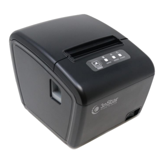
2. Appearance and components 2.1 Product appearance 1--Flap 2--Middle frame 3--Uncapping button 4--Base 5--Power switch 6--Paper feed key (FEED) 7--Paper shortage indicator light (PAPER) 8--Error indicator light (ERROR) 9--Power indicator light (POWER) 10--Front cover 11--Flap bracket 12--Rubber roller component 13--Power interface 14--Cash-box interface 15--Serial interface 16--USB interface... -
Page 9: Connection Diagram Of Control Board Components
2.2 Connection diagram of control board components The main control board, printing engine, cutter, keys, etc. are adopted for the printer to connect to the main control board through the connector or transfer board. The following is the connection diagram of the serial port +USB+ network port control board components: 2.2.1 Connection diagram of serial port +USB+ network port control board - 9 -... -
Page 10: Printer Interface
2.3 Printer interface 2.3.1 Power interface SIGNAL NAME +24V SHELL 2.3.2 Cash-box interface Cash-box control: 6-wire RJ-11 socket, output DC 24V/1A power signal to drive the cash-box for action. SIGNAL NAME FGND Drawer 1 CASH 654321 2.3.3 USB interface SIGNAL NAME VBUS D- (DATA-) D+ (DATA+) -
Page 11: Serial Interface
2.3.4 Serial interface SIGNAL NAME 2.3.5 Ethernet interface SIGNAL NAME GREEN+ GREEN - YELLOW+ YELLOW- - 11 -... -
Page 12: Buttons, Indicator Lights And Functions
3. Buttons, indicator lights and functions ) 3.1 Paper feed button( Under the condition that the printer does not alarm, press this key to deliver paper, and press this key continuously to deliver paper continuously. ) 3.2 Power indicator light( The color of the indicator light is blue. -
Page 13: Installation And Use
4. Installation and use 4.1 Interface connection Power Line Power Adapter Cash Box Line USB Cable Fig. 4.1.1 Interface connection diagram Note: the printer transmission interface in the picture will vary according to the type of machine you purchased. Please refer to the actual interface. -
Page 14: Paper Roll Installation
Warning: the cash-box interface can only be connected to the cash-box devices with a voltage of 24V/1A (it shall not be connected to telephone lines, etc.). 4.2 Paper roll installation After the connection between the power adapter and the interface cable is completed, the medium can be installed for printing. -
Page 15: Fault Treatment Guidelines
5. Fault treatment guidelines In case of printer failure, please refer to this chapter for corresponding treatment. If you still can't fix the problem, please contact the agent or manufacturer. 5.1 Power Fault Possible cause Solution The AC/DC power adapter is not Reconnect the power adapter connected properly AC/DC power adapter is in fault... -
Page 16: Paper Feed
5.3 Paper feed Fault Possible cause Solution Clear the blocked paper and install the printing Paper is blocked in the printer paper according to the operation instructions There is no paper Gear is damaged Replace the gear feed or paper feed The main board is damaged Repair or replace the main control board is abnormal... -
Page 17: Communication
5.6 Communication Fault Possible cause Solution The communication cable is not Reconnect the communication cable reliably connected to the printer The communication cables used do Use a communication cable that matches the The printer is in not match printer normal condition Communication cable or connector Replace communication cables or connectors but does not print... -
Page 18: Dis-Assembly And Assembly Of Main Components
6. Dis-assembly and assembly of main components Attentions during operation: 1) When the printer is working normally, do not remove any components of the printer or loosen any screws of the printer; 2) When you are disassembling and assembling components, please carefully check whether the connecting wires are damaged;... -
Page 19: Remove The Main Board And Interface Board Of The Printer
A. Remove the battery cover from the base. B. Remove the power switch from the base. 6.1.2 Remove the main-board, lamp board and interface iron plate of the printer Explanatory chart Diagram Remove the three PA3*8mm screws fixing the main-board with a cross screwdriver and then remove the main-board. -
Page 20: Remove The Flap And Front Cover Of The Printer
Remove the two PA3*8mm screws fixing the interface iron plate with a cross screwdriver and then remove the interface iron plate. 6.1.3 Remove the flap and front cover of the printer Explanatory chart Diagram A. First remove the pin on the right of the flap bracket from the right fixing hole of the middle frame, then remove the pin on the left from the left fixing hole, and then... - Page 21 Remove the two H3*6mm screws fixing the rubber roller component with a cross screwdriver and then remove the rubber roller component. Remove the two PA3*8mm screws fixing the flap bracket with a cross screwdriver and then remove the flap bracket. Remove the front cover according to the direction.
-
Page 22: Remove The Printer Engine
Remove the key label. Remove the two PA3*8mm screws fixing the lamp board with a cross screwdriver and then remove the lamp board. 6.1.4 Remove the printer engine Explanatory chart Diagram A. Remove the cover button according to the direction. B. -
Page 23: Printer Assembly
6.2 Printer assembly When you are assembling, simply assemble in the reverse order of dis-assembly. 7. Cleaning the printer Dust, foreign matter, stickum or other contaminants that stick to inside print head or printer may degrade the print quality. At the time of decontamination, please clean the print head according to the following methods. -
Page 24: Cleaning The Print Head
Appendix: printer explosion diagram 1. List of printer components Material name The key label Front cover Flap Flap bracket Rubber roller components Print head Lamp board Roller Middle frame Uncapping button The interface iron plate Main-board Base Battery cover Power switch Cutter Cutter holder Stepping motor... -
Page 25: Appendix: Printer Explosion Diagram
2. Explosion diagram of the whole printer - 25 -... -
Page 26: Decomposition Diagram Of Printer Engine
3. Decomposition diagram of printer engine - 26 -...
Need help?
Do you have a question about the RPT006 and is the answer not in the manual?
Questions and answers
La impresora apenas se enciende empieza a botar el papel y el boton feed no esta presionado, que puede ser?
Possible causes for the 3nStar RPT006 printer ejecting paper immediately upon turning on without the feed button being pressed could include:
1. Blocked Paper or Misalignment – Ensure there is no paper jam or misaligned paper inside the printer.
2. Damaged Gear or Paper Feed Mechanism – A damaged gear or malfunctioning paper feed mechanism could cause unintended paper ejection.
3. Main Control Board Issue – A faulty main control board may send incorrect signals to the printer, leading to unintended paper feeding.
4. Foreign Matter in Gears – Dust or debris in the gears could interfere with normal operation and cause continuous paper ejection.
5. Faulty Print Head Motor – If the print head motor is malfunctioning, it may trigger the paper feed unintentionally.
To resolve the issue, check for paper jams, clean the gears, inspect the feed mechanism, and consider repairing or replacing faulty components like the main control board or print head motor.
This answer is automatically generated
La impresora apenas se prende imprime sin parar
The 3nStar RPT006 printer may keep printing continuously when turned on due to the paper feed button being pressed continuously. According to the manual, pressing this button delivers paper, and holding it continuously results in continuous paper feeding. If the button is stuck or malfunctioning, it could cause the printer to keep printing non-stop.
This answer is automatically generated