
Related Manuals for Stack ST8130 Series


Summary of Contents for Stack ST8130 Series
- Page 1 ST8130 Series ST8130 Series Road Car Display Systems Road Car Display Systems Users Guide Users Guide Part No 542032-005...
- Page 3 Purpose of this manual Purpose of this manual This manual will help you install and use either model in the Stack ST8130 Series Road Car Display Systems. It explains how to set up and configure the system for your vehicle. Users Guide...
- Page 4 Edition Notice Edition Notice This edition is for all versions of the ST8130 Series Road Car Display Systems distributed to customers world-wide. The units of measurement used to illustrate the use of the display systems in this edition are for the UK version.
-
Page 5: Preface
Stack is a registered trademark of Stack Limited. Information in this publication is subject to change without notice and does not represent a commitment on the part of Stack Limited. No responsibility is accepted for error or omission. Copyright © 1994, 1995, 1996 Stack Limited... - Page 6 Preface STACK ST8130 Road Car Display System Fax: 01 869 245500 Users Guide...
-
Page 7: Who To Contact At Stack In Case Of Difficulty
Who to Contact at Stack in Case of Difficulty Who to Contact at Stack in Case of Difficulty Stack and its approved distributors provide a comprehensive Technical Help service to assist with your enquiries. Contact your local Stack branch or distributor. Approved Stack Distributors... - Page 8 Preface STACK ST8130 Road Car Display System Japan SARD Co, 50 Kamisotone, Higashimachi Wakabayashi, Toyotashi, Aichiken 473. Tel: 0565 53 1166 Fax: 0565 52 5482 Users Guide...
- Page 9 STACK ST8130 Series Road Car Display Systems Preface New Zealand Allport Motorsport, 5B Olive Road, P.O. Box 12-051, Penrose, Auckland. Tel: (9) 579-0113 Fax: (9) 579-0114 South Africa Automotive Technology Specialists (Pty) Limited, Private Bag, X26, Auckland Park 2006. Tel: (011) 726-6314 Fax (011) 726 2160...
- Page 10 Preface STACK ST8130 Road Car Display System Road & Racing Accessories Limited, 75-77 Moore Park Road, London SW6 2HH. Tel: 0171.736 2881 Fax 0171 736 6116 V & M Racing, Lower Place Mill, Shaw Road, Newhey, Rochdale, OL6 3SR. Tel: 01706 840066 Fax 01706 882437 U.S.A.
-
Page 11: Table Of Contents
STACK ST8130 Series Road Car Display Systems Contents Contents Contents PREFACE Related Products From Stack Limited Who to Contact at Stack in Case of Difficulty Approved Stack Distributors CONTENTS Chapter 1. Introducing the Display Systems ST8130 Model ST8131 Model How to Use this Manual Chapter 2. -
Page 12: Contents
STACK ST8130 Series Road Car Display SystemsError! Main Document Only. Contents Engine Speed (RPM) Measurement Connecting the Display System to the Ignition System Pressure sensor Temperature sensors Wheel speed sensor Pulse Amplifier Interface (ST492) Fuel Tank Sender Lap timing sensor (optional) -
Page 13: Chapter 1. Introducing The Display Systems
Chapter 1. Introducing the Display Systems Chapter 1. Introducing the Display Systems The two models in the Stack ST8130 Series Road Car Display Systems monitor and display a range of values, known as performance parameters, needed for effective car and driver management in most driving situations. -
Page 14: St8130 Model
How to Use this Manual How to Use this Manual Stack recommends that you unpack and connect the components in the system before you install it in your vehicle. This will enable you to familiarise yourself with operating the display and configuring it for the vehicle in which you intend to install it. - Page 15 STACK ST8130 Series Road Car Display Systems Chapter 1. Introducing the Display System system and setting the alarm values, and installing it in the vehicle. By the end of chapter 2, you will have set up the system so that you will be assured that it is functioning normally.
-
Page 16: Chapter 2. Getting Started
Chapter 2. Getting Started STACK ST8130 Series Road Car Display Systems Chapter 2. Getting Started Chapter 2. Getting Started This chapter guides you through the initial unpacking and setting up of the equipment for pre-installation checks and familiarisation with its operation. -
Page 17: The Display Module
STACK ST8130 Road Car Display System Chapter 2. Getting Started Optional ST8130/ST8131 Road Car Display System Items Optional ST8130/ST8131 Road Car Display System Items The optional air temperature sensor consists of the following component: Quantity Description Air Temperature Sensor (ST765) -
Page 18: Wiring Harness
Chapter 2. Getting Started STACK ST8130 Series Road Car Display Systems Wiring Harness Wiring Harness Each of the wires in the harness is labelled. Labels on short cables Connection To S1 to S4 Switches 1 to 4 Wheel speed sensor (ST8130) or pulse... -
Page 19: Connecting The Components
STACK ST8130 Road Car Display System Chapter 2. Getting Started Connecting the Components Connecting the Components 1. Connect the wiring harness to the display module. 2. Connect the four switches to the cables labelled S1 to S4. 3. Connect each of the sensors that you have purchased to the appropriate wire in the wiring harness, as shown above. -
Page 20: Chapter 3. Operating The Display System
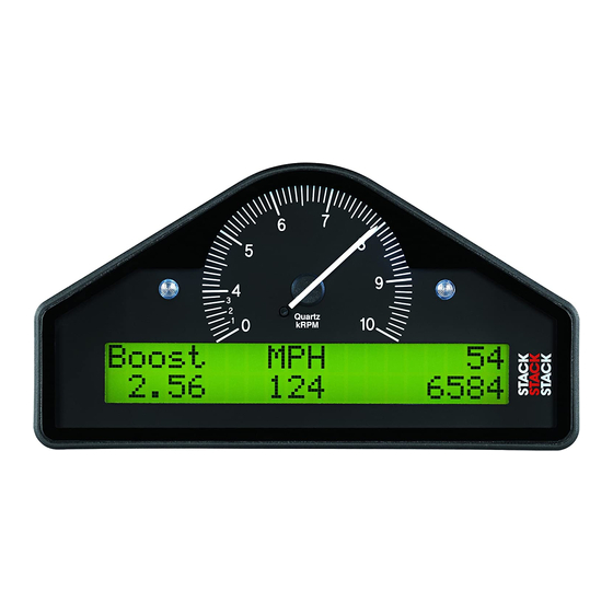
Chapter 3. Operating the Display System STACK ST8130 Series Road Car Display Systems Chapter 3. Operating the Display System Chapter 3. Operating the Display System This chapter takes you through the operation of the system so that you can familiarise yourself with its use before you install it in the vehicle. - Page 21 STACK ST8130 Series Road Car Display Systems Chapter 3. Operating the Display System Display Layer 1 Display Layer 1 Display layer 1 shows: Fuel level (Note when the amount of fuel in the tank is changed that • the displayed value changes slowly ~1ltr/5sec.) Current speed (MPH or km/h) •...
- Page 22 Chapter 3. Operating the Display System STACK ST8130 Series Road Car Display Systems Oil pressure (Oil P) • Note that the minimum oil and water temperature for which the display gives a true reading is 12°C or 53°F. The unit displays temperatures that are less than this as 0°C or 32°F.
-
Page 23: Peak Values (Tell Tales)
STACK ST8130 Series Road Car Display Systems Chapter 3. Operating the Display System Display Layer 5 Display Layer 5 Lap 12 Lap 12 Best Best 1:35.10 135 1:35.10 135 1:35.06 1:35.06 Display layer 5 shows: • Number of the current lap •... - Page 24 Chapter 3. Operating the Display System STACK ST8130 Series Road Car Display Systems Parameter Type of Peak Gated to RPM Value Engine Speed (RPM) Maximum Oil Temperature Maximum Water Temperature Maximum Oil Pressure Minimum Fuel Level Value @ Reset Battery Voltage...
-
Page 25: Alarms
STACK ST8130 Series Road Car Display Systems Chapter 3. Operating the Display System If the engine is running below its gate value, the peak values are not reset to the current values but are set to the values in the following... - Page 26 Chapter 3. Operating the Display System STACK ST8130 Series Road Car Display Systems from being triggered when, for example, the engine is either not running, is idling, or is being warmed up. Once the engine has been running above the gated RPM for one second, any problems will trigger an immediate warning.
- Page 27 STACK ST8130 Series Road Car Display Systems Chapter 3. Operating the Display System Displaying an Alarm Displaying an Alarm When an alarm condition occurs, the built-in red warning light turns on, and the digital display gives a warning message to show the type of alarm: Note that the low fuel warning is indicated by the amber light.
-
Page 28: Lap Times
Chapter 3. Operating the Display System STACK ST8130 Series Road Car Display Systems Lap times Lap times The lap time for each lap is recorded either by the infra-red lap time sensor when passing the lap time beacon or when the driver presses Switch 4. -
Page 29: Chapter 4. Configuring The Display System
STACK ST8130 Series Road Car Display Systems Chapter 4. Configuring the Display System Chapter 4. Configuring the Display System Chapter 4. Configuring the Display System Configuration mode Configuration mode You put the Display System into configuration mode by pressing Switches 1 and 2 together. This should give a display similar to the... - Page 30 Chapter 4. Configuring the Display System STACK ST8130 Series Road Car Display Systems Switching Alarms on or off Switching Alarms on or off You can enable (switch on) or disable (switch off) each of the alarm warnings by pressing and holding Switch 1 and then pressing Switch 2.
- Page 31 STACK ST8130 Series Road Car Display Systems Chapter 4. Configuring the Display System Configurable Parameters Configurable Parameters The configurable parameters are displayed in the following order: Configurable Setting Required Switchable Parameter Parameter Shift RPM RPM at or above which the gear shift light is to...
- Page 32 Chapter 4. Configuring the Display System STACK ST8130 Series Road Car Display Systems Examples of the displays for each of the configuration items are shown below. Shift RPM: Shift RPM: EDIT TEST EDIT TEST Shift RPM Shift RPM 7000 7000...
- Page 33 STACK ST8130 Series Road Car Display Systems Chapter 4. Configuring the Display System Low battery voltage: Low battery voltage: EDIT TEST EDIT TEST Low Batt Low Batt 10.0 10.0 Low oil pressure: Low oil pressure: EDIT TEST EDIT TEST Low Oil...
- Page 34 Chapter 4. Configuring the Display System STACK ST8130 Series Road Car Display Systems Wheel speed pulses: Wheel speed pulses: W.S. Pulses/Rev W.S. Pulses/Rev Wheel circumference: Wheel circumference: Wheel Cir Wheel Cir (mm) (mm) 1000 1000 Users Guide...
-
Page 35: Wheel Pulses And Circumferences
STACK ST8130 Series Road Car Display Systems Chapter 4. Configuring the Display System Wheel Pulses and Circumferences Wheel Pulses and Circumferences Calculations for the ST8130 (ST492 Pulse Amplifier) Calculations for the ST8130 (ST492 Pulse Amplifier) You must supply a value for the wheel circumference that you obtain from one of the following calculations: 1. - Page 36 Chapter 4. Configuring the Display System STACK ST8130 Series Road Car Display Systems 3. If you know the number of pulses generated for one mile (UK/EU version only): 1609344 ÷ pulses per mile = wheel circumference Set the number of pulses per rev to 1.
- Page 37 STACK ST8130 Series Road Car Display Systems Chapter 4. Configuring the Display System If the sensor is mounted on a driveshaft or the propshaft, set the circumference to: Actual wheel circumference ÷ differential ratio -where the differential ratio is calculated as: crownwheel (ring) teeth ÷...
-
Page 38: Calibrating The Fuel Level
You may wish to enter these values into the table on p30. If you ever have to return the unit for servicing, supplying the values from this table will allow Stack to automatically recalibrate the fuel display so that you will not have to repeat this process. - Page 39 STACK ST8130 Series Road Car Display Systems Chapter 4. Configuring the Display System Note: The petrol (gas) pumps may shut off, if the petrol delivery is interrupted for a time. 2. Select the Fuel Tank Sender calibration display. Hold Switch 1 down and press Switch 2. This gives a display similar...
- Page 40 Chapter 4. Configuring the Display System STACK ST8130 Series Road Car Display Systems The flowchart on the next page summarises the steps in the calibration process. Users Guide...
- Page 41 STACK ST8130 Series Road Car Display Systems Chapter 4. Configuring the Display System Start fuel tank calibration process: Press Switches 1 and 2. Switch 1 and 2 Set initial Tank Qty value using Switch 1 to decrease value or Switch 2 to increase value.
- Page 42 ST8130 or ST8131 Road Car Display System. Check with your Stack dealer if this is the case. When you wish to return to the normal display, press Switch 4.
-
Page 43: Chapter 5. Installing The Display System
STACK ST8130 Series Road Car Display SystemsError! Main Document Only.Chapter 5. Installing the Display Sys Chapter 5. Installing the Display System Chapter 5. Installing the Display System Who can install the Display System? Who can install the Display System? The Display System can be installed by anyone competent in fitting electrical and mechanical accessories to cars. -
Page 44: Fitting The Display Module
Error! Main Document Only.Chapter 5. Installing the Display SystemSTACK ST8130 Series Road Car Display Systems Fitting the Display Module Fitting the Display Module The Display Module is fitted into a cut-out in the instrument panel/dashboard and secured using the two U-brackets at the rear. The dimensions for the cut-out are shown below. -
Page 45: Switches
STACK ST8130 Series Road Car Display SystemsError! Main Document Only.Chapter 5. Installing the Display Sys Switches Switches The four switches are used to control the functions of the Display System. The normal functions of the four switches are: Switch Functions Switch 1 Show the peak values. -
Page 46: Warning Lights
Error! Main Document Only.Chapter 5. Installing the Display SystemSTACK ST8130 Series Road Car Display Systems Warning lights Warning lights The Display Module has two built-in warning lights. The left-hand (amber) light is the fuel level warning light and the right-hand (red) light alerts the driver whenever an alarm has been triggered. -
Page 47: Connecting The Display System To The Ignition System
STACK ST8130 Series Road Car Display SystemsError! Main Document Only.Chapter 5. Installing the Display Sys Connecting the Display System to the Ignition System Connecting the Display System to the Ignition System The Display System can be connected to engines with a variety of ignition systems. - Page 48 Error! Main Document Only.Chapter 5. Installing the Display SystemSTACK ST8130 Series Road Car Display Systems Standard contact breaker system Standard contact breaker system Connect the ES (Engine Speed) wire to the negative terminal on the coil. Series Resistor Connection Series Resistor Connection...
-
Page 49: Pressure Sensor
STACK ST8130 Series Road Car Display SystemsError! Main Document Only.Chapter 5. Installing the Display Sys Pressure sensor Pressure sensor Fitting the pressure sensor Fitting the pressure sensor The Display System is supplied with one of the following types of pressure sensors: the Stack ST744, the ST745, or the ST746. -
Page 50: Temperature Sensors
Error! Main Document Only.Chapter 5. Installing the Display SystemSTACK ST8130 Series Road Car Display Systems Temperature sensors Temperature sensors The Display System is supplied with two each of one of the following types of temperature sensor: Stack ST760, ST761, ST762 or ST764: ST760 has a 1/8 BSP (Taper) thread ST761 has a M14 x 1.5mm thread. -
Page 51: Wheel Speed Sensor
STACK ST8130 Series Road Car Display SystemsError! Main Document Only.Chapter 5. Installing the Display Sys Wheel speed sensor Wheel speed sensor The ST8131 Display System is supplied with one Stack ST670 proximity sensor as a standard feature which must be fitted if the vehicle is to comply with the legal requirement for an on-road speedometer. -
Page 52: Pulse Amplifier Interface (St492)
Error! Main Document Only.Chapter 5. Installing the Display SystemSTACK ST8130 Series Road Car Display Systems Pulse Amplifier Interface (ST492) Pulse Amplifier Interface (ST492) Introduction Introduction This amplifier is designed to convert the output of an existing sensor, which generates a pulsed signal which is not compatible with the ST8130 system’s channel input requirements. - Page 53 STACK ST8130 Series Road Car Display SystemsError! Main Document Only.Chapter 5. Installing the Display Sys For best performance, the following precautions should be taken: Bond strength is dependent upon the amount of adhesive to surface contact development. Firm application pressure develops better adhesive contact and thus improves bond strength.
- Page 54 Error! Main Document Only.Chapter 5. Installing the Display SystemSTACK ST8130 Series Road Car Display Systems Electrical Electrical The amplifier connects into the ST8130 system via a four way Mini Sure Seal (MSS) socket, the larger of the two connectors on the amplifier. Use the extender cable with an MSS connector at each end to connect the amplifier to the WS input on the harness.
-
Page 55: Fuel Tank Sender
STACK ST8130 Series Road Car Display SystemsError! Main Document Only.Chapter 5. Installing the Display Sys ST492 Technical Specification ST492 Technical Specification Supply : From ST8130 input Output characteristics : ST8130 compatible Input impedance : >50K Ohms Operating temperature range : -20 to +80 ºC / -4 to 176 ºF... -
Page 56: Lap Timing Sensor (Optional)
Error! Main Document Only.Chapter 5. Installing the Display SystemSTACK ST8130 Series Road Car Display Systems Lap timing sensor (optional) Lap timing sensor (optional) The lap timing sensor is actuated by an infra-red beacon positioned at the side of the circuit. The sensor is fixed to a rigid bracket mounted at a convenient position on the outside of the vehicle where it is able to detect the signals from the beacon. -
Page 57: Trackside Infra-Red Lap Beacon (Optional)
STACK ST8130 Series Road Car Display SystemsError! Main Document Only.Chapter 5. Installing the Display Sys Trackside Infra-Red Lap Beacon (optional) Trackside Infra-Red Lap Beacon (optional) The ST544 trackside infra-red lap beacon should be located as follows: As near to the start-finish line as possible •... -
Page 58: Air Temperature Sensor (Optional)
Error! Main Document Only.Chapter 5. Installing the Display SystemSTACK ST8130 Series Road Car Display Systems Power supply to Trackside beacon Power supply to Trackside beacon The beacon operates from a 12v DC supply. A sealed lead-acid battery with a minimum rating of 2.5 Amp/hour is recommended. This provides about 15 hours of operation. - Page 59 STACK ST8130 Series Road Car Display SystemsError! Main Document Only.Chapter 5. Installing the Display Sys you are installing, you should not need to extend any of the individual wires in the harness. Users Guide...
- Page 60 Error! Main Document Only.Chapter 5. Installing the Display SystemSTACK ST8130 Series Road Car Display Systems Extender wires for connecting the air temperature and wheel speed sensors to the wiring harness are available in the following lengths: • 700mm / 2’3”...
-
Page 61: Checks And Alarms
STACK ST8130 Series Road Car Display SystemsError! Main Document Only.Chapter 5. Installing the Display Sys Connect the wires when all the sensors are in position and you have • secured the wiring harness. Wiring labels Wiring labels See Chapter 2 if you need to check the labels used to identify the... -
Page 62: Chapter 6. Troubleshooting
Chapter 6. Troubleshooting STACK ST8130 Road Car Display System Chapter 6. Troubleshooting Chapter 6. Troubleshooting Symptom Possible Cause Remedy Notes Display is dead Ignition is off Turn ignition on B + is 19w connector pin (no backlight, Battery is dead... - Page 63 STACK ST8130 Series Road Car Display Systems Chapter 6. Troubleshooting Symptom Possible Cause Remedy Notes The Low Oil P Pressure sensor Replace sensor message does has failed NOT appear on power up. The warning light Sensor connections Check for continuity A reading of is not turned on.
- Page 64 Chapter 6. Troubleshooting STACK ST8130 Road Car Display System Symptom Possible Cause Remedy Notes Water or Oil A temperature Disconnect sensor temperature sensor has failed and short its leads display gives a together. If the fixed temperature reading changes, reading of 0 ° C or replace the sensor 0 °...
- Page 65 STACK ST8130 Series Road Car Display Systems Chapter 6. Troubleshooting Symptom Possible Cause Remedy Notes Fixed pressure Pressure sensor Replace sensor reading of 0 PSI or has failed 0.0 Bar or suspected low/slow reading Faulty sensor Check pressure Check plumbing...
- Page 66 Chapter 6. Troubleshooting STACK ST8130 Road Car Display System Symptom Possible Cause Remedy Notes Switch 1: Show Switch 1 faulty Replace switch Disconnect peak values does switch and not work short its leads. If display changes, replace Switch 1. Otherwise check wiring.
- Page 67 STACK ST8130 Series Road Car Display Systems Chapter 6. Troubleshooting Symptom Possible Cause Remedy Notes Switch 3: Switch 3 faulty Replace switch Disconnect switch Change and short its leads. display layer If display changes, function does replace Switch 3. not work Otherwise check wiring.
- Page 68 Chapter 6. Troubleshooting STACK ST8130 Road Car Display System Symptom Possible Cause Remedy Notes External Bulb has burnt out Replace bulb Swap with the other warning light light to confirm dead when the burnt-out bulb. If display not burnt out, check warning light is wiring.
- Page 69 STACK ST8130 Series Road Car Display Systems Chapter 6. Troubleshooting Symptom Possible Cause Remedy Notes No RPM Incorrect wiring Check the See instructions speed reading connection of the supplied in this engine speed wire manual. If to the ignition connected directly...
- Page 70 Chapter 6. Troubleshooting STACK ST8130 Road Car Display System Symptom Possible Cause Remedy Notes Displayed speed System configured Reconfigure the value too high or with wrong number system with correct too low by a of targets per wheel values constant %-age revolution amount.
- Page 71 STACK ST8130 Series Road Car Display Systems Chapter 6. Troubleshooting Symptom Possible Cause Remedy Notes No alarms for All the alarms have Switch on the Alarms only water, oil, or fuel been switched off required alarms operate when (temperatures and...
- Page 72 Chapter 6. Troubleshooting STACK ST8130 Road Car Display System Symptom Possible Cause Remedy Notes Lap time is not Lap marker Check lap marker Press lap displayed receiver lead faulty wiring switch 4. automatically (Automatic Lap marker Replace lap marker If display...
-
Page 73: Appendix A. Template For The Display Module
STACK ST8130 Series Road Car Display Systems Appendix A. Template for the Display Module Appendix A. Template for the Display Module Appendix A. Template for the Display Module Use the template on the following page for cutting out an aperture for the Display System. - Page 74 Appendix A. Template for the Display Module STACK ST8130 Series Road Car Display Systems Users Guide...
- Page 75 STACK ST8130 Series Road Car Display Systems Appendix A. Template for the Display Module Reverse template Users Guide...
-
Page 76: Appendix B. Wiring Harness Diagram
Appendix B. Wiring Harness Schematic Diagram STACK ST8130 Road Car Display System Appendix B. Wiring Harness Diagram Appendix B. Wiring Harness Diagram Users Guide... -
Page 77: Appendix C. Summary Of Switch Functions
STACK ST8130 Series Road Car Display Systems Appendix C. Summary of Switch Functions Appendix C. Summary of Switch Functions Appendix C. Summary of Switch Functions Normal Operation Normal Operation Switch or Functions Switches Switch 1 Show the peak values Switch 2... - Page 78 Appendix C. Summary of Switch Functions STACK ST8130 Series Road Car Display Systems System Configuration Mode System Configuration Mode Switch or Functions Switches Switch 1 Decrease the alarm value of the parameter being displayed Switch 2 Increase the alarm value of the parameter being displayed Switches 1 &...
-
Page 79: Returned Goods Form
Appendix C. Summary of Switch Functions Returned Goods Form Returned Goods Form In the unlikely event of a Stack part developing a fault and requiring repairs, you are kindly requested to send the part back to Stack Ltd with a completed Returned Goods Form. -
Page 80: Index
Index STACK 8130 Series Road Car Display Systems Index Index Air temperature Custom configured ST8130, 29 alarm, 19 Datalogging subsystem display, 10 wiring label, 6 wiring label, 6 Digital display panel, 5 Air temperature sensor Dimensions, 30 installation, 44 Display... - Page 81 STACK ST8130 Series Road Car Display Systems Index Gear shift RPM, 19 Performance parameters, 1 Gear shift warning light, 16 Points connection, 34 wiring label, 6 Power supply, 6, 7 High oil temperature alarm, 19 Pressure sensor. See Oil pressure sensor...
- Page 82 Index STACK 8130 Series Road Car Display Systems Template for the Display Module, 58 alarm, 14, 19 Tools needed, 29 display, 10 Trackside infra-red beacon. See Beacon Water temperature sensor Trip meter installation, 36 display, 9 wiring label, 6 resetting, 31...
Need help?
Do you have a question about the ST8130 Series and is the answer not in the manual?
Questions and answers