
Related Manuals for Stack ST8100


Summary of Contents for Stack ST8100
- Page 1 ST8100 Display System ST8100 Display System Users Guide Users Guide Part No./IssueNo. 542030-004...
- Page 3 This will allow us to keep you up to date on the latest developments from Stack. Purpose of this manual Purpose of this manual This manual will help you install and use the Stack ST8100 Display System. It explains how to set up and configure the system for your vehicle. Edition Notice...
-
Page 4: Preface
Stack is a registered trademark of Stack Limited. Information in this publication is subject to change without notice and does not represent a commitment on the part of Stack Limited. No responsibility is accepted for error or omission. Copyright © 1994, 1995, 1996 Stack Limited... -
Page 5: Who To Contact At Stack In Case Of Difficulty
Who to Contact at Stack in Case of Difficulty Who to Contact at Stack in Case of Difficulty Stack and its approved distributors provide a comprehensive Technical Help service to assist with your enquiries. Contact your local Stack branch or distributor. Approved Stack Distributors... - Page 6 Preface STACK ST8100 Display System Japan SARD Co, 50 Kamisotone, Higashimachi Wakabayashi, Toyotashi, Aichiken 473. Tel: 0565 53 1166 Fax: 0565 52 5482 New Zealand Allport Motorsport, 5B Olive Road, P.O. Box 12-051, Penrose, Auckland. Tel: (9) 579-0113 Fax: (9) 579-0114 South Africa Automotive Technology Specialists (Pty) Limited, Private Bag, X26, Auckland Park 2006.
- Page 7 STACK ST8100 Display System Preface Prodrive Ltd, Acorn Way, Banbury, Oxon, OX16 7XS. Tel: 01295 273355 Fax 01295 271188 Road & Racing Accessories Ltd, 75-77 Moore Park Road, London SW6 2HH. Tel: 0171.736 2881 Fax 0171 736 6116 V & M Racing, Lower Place Mill, Shaw Road, Newhey, Rochdale, OL6 3SR.
- Page 8 Preface STACK ST8100 Display System Users Guide...
-
Page 9: Table Of Contents
STACK ST8100 Display System Contents Contents Contents PREFACE Related Products From Stack Limited Who to Contact at Stack in Case of Difficulty Approved Stack Distributors CONTENTS Chapter 1. Introducing the Display System How to Use this Manual Chapter 2. Getting Started... -
Page 10: Contents
Contents STACK ST8100 Display System Pressure sensors Temperature sensors Wheel speed sensor (optional) Lap timing sensor (optional) Trackside Infra-Red Lap Beacon (optional) Lateral Acceleration sensor (optional) Wiring harness Checks and Alarms Chapter 6. Troubleshooting Appendix A. Template for the Display Module Appendix B. -
Page 11: Chapter 1. Introducing The Display System
Chapter 1. Introducing the Display System Chapter 1. Introducing the Display System Chapter 1. Introducing the Display System The Stack ST8100 Display System monitors and displays a range of values, known as performance parameters, needed for effective car and driver management in most competitive situations. -
Page 12: How To Use This Manual
Please note that this manual does not attempt to explain how to interpret or use the information from the ST8100 Display System, as this is very specific to the type of vehicle in which it is installed and the type of competition in which the vehicle is engaged. -
Page 13: Chapter 2. Getting Started
Switches (supplied with and to be connected to the wiring harness) Optional ST8100 Display System Items Optional ST8100 Display System Items The ST8100 Display System can be used with the following optional components: Quantity Description RPM Sensor (ST696 Opto Isolator or ST697 H.T. Pick-up) -
Page 14: The Display Module
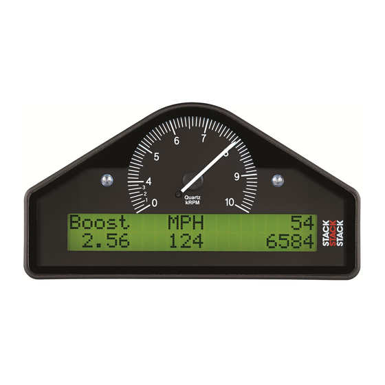
Chapter 2. Getting Started STACK ST8100 Display System The Display Module The Display Module The Display Module consists of an analog tachometer and a digital display panel. The Display Module is connected to a variety of sensors by a wiring harness. -
Page 15: Connecting The Components
STACK ST8100 Display System Chapter 2. Getting Started Labels on Long Cables: Connection To Engine Speed (RPM) Oil temperature sensor Water temperature sensor Oil pressure sensor Fuel pressure sensor Lateral Acceleration sensor Battery Positive Battery Negative (Earth) Connecting the Components Connecting the Components 1. -
Page 16: Chapter 3. Operating The Display System
Chapter 3. Operating the Display System STACK ST8100 Display System Chapter 3. Operating the Display System Chapter 3. Operating the Display System This chapter takes you through the operation of the system so that you can familiarize yourself with its use before you install it in the vehicle. - Page 17 STACK ST8100 Display System Chapter 3. Operating the Display System The format of the values in these displays will vary for ð systems supplied outside the UK, as the parameters are displayed in different units. Display Layer 1 Display Layer 1...
- Page 18 Chapter 3. Operating the Display System STACK ST8100 Display System Oil Pressure (OIL P) • Note: The fuel pressure is displayed as 0.1 PSI (US and UK) and as 0.01 Bar (EU) on the Low Fuel Pressure version of the display system.
- Page 19 STACK ST8100 Display System Chapter 3. Operating the Display System Press Switch 3 to change the display back either to layer 1 or to layer 5 if you have the Corner Speed option. Users Guide...
- Page 20 Chapter 3. Operating the Display System STACK ST8100 Display System Display Layer 5 Display Layer 5 This display is available when the optional Corner Speed feature is installed. Display layer 5 shows: Current speed (SPEED) • Maximum speed straight (MAX) •...
-
Page 21: Peak Values (Tell Tales)
STACK ST8100 Display System Chapter 3. Operating the Display System Peak Values (Tell Tales) Peak Values (Tell Tales) The system can display the peak values (sometimes called ‘tell-tales’) that have been recorded during a run for all the monitored parameters. - Page 22 Chapter 3. Operating the Display System STACK ST8100 Display System Resetting the Peak Values Resetting the Peak Values You can reset all of the peak values, except the fastest lap time, manually. All peak values are reset at the same time. If the engine is running at or above its gate value when the peak values are reset, they are set to the current value of each performance parameter.
-
Page 23: Alarms
STACK ST8100 Display System Chapter 3. Operating the Display System Alarms Alarms The Display System has built-in warnings to alert the driver when certain parameters either exceed or fall below their alarm values. For example, a warning is signalled if the fuel pressure falls below its alarm value or if the oil temperature rises above its alarm value. - Page 24 Chapter 3. Operating the Display System STACK ST8100 Display System Displaying an Alarm Displaying an Alarm When an alarm condition occurs, the built-in amber warning light turns on, and the digital display gives a warning message to show the type of...
-
Page 25: Lap Times
STACK ST8100 Display System Chapter 3. Operating the Display System Lap times Lap times The lap time is displayed for eight seconds either when triggered by the infra-red lap time sensor on passing the lap time beacon or when the driver presses Switch 4. -
Page 26: Gear Shift Light
Chapter 3. Operating the Display System STACK ST8100 Display System Gear shift light Gear shift light The gear shift light comes on when the engine RPM exceeds a predefined value. See "Configuring the Display System" for information about setting this value. -
Page 27: Chapter 4. Configuring The Display System
STACK ST8100 Display System Chapter 4. Configuring the Display System Chapter 4. Configuring the Display System Chapter 4. Configuring the Display System Configuration mode Configuration mode You put the Display System into configuration mode by pressing Switches 1 and 2 together. You then work through the configurable parameters in a preset sequence. - Page 28 Chapter 4. Configuring the Display System STACK ST8100 Display System Setting or resetting configuration values Setting or resetting configuration values Use Switch 1 to decrease the value being configured and Switch 2 to increase it. The rate at which the value increases or decreases itself increases while the switch is being held down.
- Page 29 STACK ST8100 Display System Chapter 4. Configuring the Display System High water temperature: High water temperature: High oil temperature: High oil temperature: Low fuel pressure: Low fuel pressure: Low oil pressure: Low oil pressure: Low battery voltage Low battery voltage...
-
Page 30: Leaving Configuration Mode
Chapter 4. Configuring the Display System STACK ST8100 Display System Switching Alarms on or off Switching Alarms on or off You can enable (switch on) or disable (switch off) each of the alarm warnings by pressing and holding Switch 1 and then pressing Switch 2. -
Page 31: Chapter 5. Installing The Display System
No special tools other than normal workshop tools are needed. Preconfigured Display Systems Preconfigured Display Systems Use the instructions in the previous chapters to set up, operate, and configure the ST8100 before installing it in the vehicle. Custom Configured Custom Configured Display Systems Display Systems If you have purchased a Display System that has been custom configured for you, the system may include components not described in this book. -
Page 32: Fitting The Display Module
Error! Main Document Only.Chapter 5. Installing the Display System STACK ST8100 Display System Fitting the Display Module Fitting the Display Module The Display Module is fitted into a cut-out in the instrument panel/dashboard and secured using the two U-brackets at the rear. The dimensions for the cut-out are shown below. -
Page 33: Switches
Error! Main Document Only.Chapter 5. Installing the Display System STACK ST8100 Display System Switches Switches The four switches are used to control the functions of the Display System. The normal functions of the four switches are: Switch Functions Switch 1 1. -
Page 34: Warning Lights
Stack can supply suitable external warning lights for installation in the dashboard as well as shrouded versions that can be mounted on top of the dashboard. -
Page 35: Connecting The Display System To The Ignition System
Error! Main Document Only.Chapter 5. Installing the Display System STACK ST8100 Display System Connecting the Display System to the Ignition System Connecting the Display System to the Ignition System The Display System can be connected to engines with a variety of ignition systems. - Page 36 Error! Main Document Only.Chapter 5. Installing the Display System STACK ST8100 Display System Ignition System Normally Fitted To Connection Point Bosch Citroen AX 'Sport' and Tacho output (coil negative) with 'GT' 100K series resistor Bosch 3-pin CD Porsche 911 Carrera...
- Page 37 Error! Main Document Only.Chapter 5. Installing the Display System STACK ST8100 Display System The following connections are shown in greater detail: Standard contact breaker system • Series Resistor Connection • Contactless system • Lucas CD (Spark box) system • The connection of the Display System to these types of ignition system is...
- Page 38 Error! Main Document Only.Chapter 5. Installing the Display System STACK ST8100 Display System Contactless system Contactless system Connect the E.S. (Engine Speed) wire to the contactless ignition system as shown in the diagram below. Lucas CD (Spark box) system Lucas CD (Spark box) system Connect the E.S.
-
Page 39: Pressure Sensors
Fitting the pressure sensors The Display System is supplied with two each of the following types of pressure sensors: the Stack ST744, the ST745, or the ST746. The ST744 pressure sensor has an M10 x 1 thread (UK, EC). The ST745 pressure sensor has a 1/8" NPTF thread (USA). -
Page 40: Temperature Sensors
Temperature sensors Temperature sensors The Display System is supplied with two each of one of the following types of temperature sensor: Stack ST 760, ST761, ST762, ST763, or ST764: The ST760 temperature sensor has two terminals and a 1/8" BSP taper thread. - Page 41 Error! Main Document Only.Chapter 5. Installing the Display System STACK ST8100 Display System The ST763 temperature sensor is connected by the red WT or OT wire. • The unused black wire should be tied back to the harness. If this type...
-
Page 42: Wheel Speed Sensor (Optional)
Wheel speed sensor (optional) The Display System is supplied with one Stack ST670 proximity sensor as an optional feature. This sensor is used to measure wheel speed in order to display the vehicle's speed in MPH or km/h. The sensor provides an electrical pulse to the system each time a ferrous object, such as a wheel bolt, passes near to the end of the sensor. -
Page 43: Lap Timing Sensor (Optional)
Error! Main Document Only.Chapter 5. Installing the Display System STACK ST8100 Display System Lap timing sensor Lap timing sensor (optional) (optional) The lap timing sensor is actuated by an infra-red beacon positioned at the side of the circuit. The sensor is fixed to a rigid bracket mounted at a convenient position on the outside of the vehicle where it is able to detect the signals from the beacon. -
Page 44: Trackside Infra-Red Lap Beacon (Optional)
Error! Main Document Only.Chapter 5. Installing the Display System STACK ST8100 Display System Trackside Infra-Red Lap Beacon (optional) Trackside Infra-Red Lap Beacon (optional) The ST544 trackside infra-red lap beacon should be located as follows: As near to the start-finish line as possible •... -
Page 45: Lateral Acceleration Sensor (Optional)
The most suitable place to fit the lateral Acceleration sensor is as close as possible to the vehicle's centre of gravity. The sensor must be positioned vertically with its side with the Stack label facing the left side of the vehicle. The side from which its cable emerges can be positioned at any angle. -
Page 46: Wiring Harness
Occasionally, an individual branch may need to be extended or significantly shortened. If the standard harness is totally unsuitable for your vehicle, contact Stack for details of custom harnesses. Provided that you have chosen suitable... -
Page 47: Checks And Alarms
Error! Main Document Only.Chapter 5. Installing the Display System STACK ST8100 Display System heatshrink sleeving, to provide additional strain relief for the cable where it enters the 19-way connector. Connect the wires when all the sensors are in position and you have •... -
Page 48: Chapter 6. Troubleshooting
Chapter 6. Troubleshooting STACK ST8100 Display System Chapter 6. Troubleshooting Chapter 6. Troubleshooting Symptom Possible Cause Remedy Notes Display is dead Ignition is off Turn ignition on The power lead is labelled B+ & (no backlight, Battery is dead Recharge or... - Page 49 STACK ST8100 Display System Chapter 6. Troubleshooting Symptom Possible Cause Remedy Notes The !! LOW OIL P Pressure sensor Replace sensor Swap with the !! message does has failed fuel pressure NOT appear on sensor to power up. confirm fault...
- Page 50 Chapter 6. Troubleshooting STACK ST8100 Display System Symptom Possible Cause Remedy Notes Display gives a A temperature Replace sensor Disconnect fixed temperature sensor has failed sensor and reading of 0 ° C or short its leads 0 ° F when engine together.
- Page 51 STACK ST8100 Display System Chapter 6. Troubleshooting Users Guide...
- Page 52 Chapter 6. Troubleshooting STACK ST8100 Display System Symptom Possible Cause Remedy Notes Fixed pressure Pressure sensor has Replace sensor Swap with the reading of 0 PSI or failed other pressure 0.0 Bar or sensor to confirm suspected low/slow fault reading...
- Page 53 STACK ST8100 Display System Chapter 6. Troubleshooting Symptom Possible Cause Remedy Notes Switch 1: Show Switch 1 faulty Replace switch Disconnect peak values does switch and not work short its leads. If display changes, replace Switch 1. Otherwise check wiring.
- Page 54 Chapter 6. Troubleshooting STACK ST8100 Display System Symptom Possible Cause Remedy Notes Switch 3: Switch 3 faulty Replace switch Disconnect switch Change and short its leads. display layer If display changes, function does replace Switch 3. not work Otherwise check wiring.
- Page 55 STACK ST8100 Display System Chapter 6. Troubleshooting Symptom Possible Cause Remedy Notes External Bulb has burnt out Replace bulb Swap with the other warning light light to confirm dead when the burnt-out bulb. If display not burnt out, check warning light is wiring.
- Page 56 Chapter 6. Troubleshooting STACK ST8100 Display System Symptom Possible Cause Remedy Notes No RPM Incorrect wiring Check the See instructions speed reading connection of the supplied in this engine speed wire manual. If to the ignition connected directly system (or sensor,...
- Page 57 STACK ST8100 Display System Chapter 6. Troubleshooting Symptom Possible Cause Remedy Notes Displayed speed System configured Reconfigure the Typical wheel value too high or with wrong number system with correct circumference too low by a of targets per wheel values...
- Page 58 Chapter 6. Troubleshooting STACK ST8100 Display System Symptom Possible Cause Remedy Notes No alarms for All the alarms have Switch on the Alarms only water, oil, or fuel been switched off required alarms operate when (temperatures and the engine is...
-
Page 59: Appendix A. Template For The Display Module
STACK ST8100 Display System Appendix A. Template for the Display Module Appendix A. Template for the Display Module Appendix A. Template for the Display Module Use the template on the following page for cutting out an aperture for the Display System. - Page 60 Appendix A. Template for the Display Module STACK ST8100 Display System...
- Page 61 STACK ST8100 Display System Appendix A. Template for the Display Module...
-
Page 62: Appendix B. Wiring Harness Schematic Diagram
Appendix B. Wiring Harness Schematic Diagram STACK ST8100 Display System Appendix B. Wiring Harness Schematic Diagram Appendix B. Wiring Harness Schematic Diagram Users Guide... -
Page 63: Returned Goods Form
Returned Goods Form Returned Goods Form In the unlikely event of a Stack part developing a fault and requiring repairs, you are kindly requested to send the part back to Stack Ltd with a completed Returned Goods Form. Returning a part without this form will lengthen the repair time and possibly increase the cost of the repair. -
Page 64: Appendix D. Summary Of Switch Functions
Appendix D. Summary of Switch Functions STACK ST8100 Display System Appendix D. Summary of Switch Functions Appendix D. Summary of Switch Functions Normal Operation Normal Operation Functions Switch or Switches Show Peak Values Switch 1 Change Display Layer Switch 3... -
Page 65: Index
Water Temperature, 12 HIGH OIL T, 16 alarm warning light, wiring label, 4 HIGH WATER, 16 alarms, 12 Installing the Stack ST8100, 20 alarms, switching on or off, 19 labels on wiring, 4 analog tachometer, 4 lap number, 8... - Page 66 Index STACK ST8100 Display System performance parameters, 1 Template for the Display Module, 45 power supply, 5 tools needed, 20 power supply to trackside beacon, 31 trackside infra-red lap beacon, 31 pressure sensors, 27 unpacking, 3 resetting the peak values, 11...
Need help?
Do you have a question about the ST8100 and is the answer not in the manual?
Questions and answers