Table of Contents
Advertisement
Advertisement
Table of Contents

Related Manuals for Stack ST8100


Summary of Contents for Stack ST8100
-
Page 1: Users Guide
ST8100 Display System Users Guide Users Guide PART NO. ST54030-007... -
Page 2: Edition Notice
This will allow us to keep you up to date on the latest developments from Stack. Edition Notice This edition is for all versions of the ST8100 Display System distributed to customers worldwide. The units of measurement used to illustrate the use of the Display System in this edition are for the UK version. -
Page 3: Related Products From Stack Limited
Technical Help service to assist with your enquiries. Contact your local Stack branch or distributor. For a current list of distributors log onto the Stack websites and click on the WHERE TO BUY TAB at the top of the home page. -
Page 4: Table Of Contents
Related Products From Stack Limited..........ii alarm for fuel pressure, 12 lateral G-force sensor, wiring label, 5 Who to Contact at Stack in Case of Difficulty ........ii alarm for oil pressure, 12 maximum water temperature alarm, 17, 18 alarm for oil temperature, 12 oil pressure, 7 CONTENTS.................. -
Page 5: Normal Operation
Preface STACK ST8100 Display System STACK ST8100 Display System Appendix D. Summary of Switch Functions The Stack ST8100 Display System monitors and displays Appendix D. Summary of Switch Functions a range of values, known as performance parameters, Normal Operation needed for effective car and driver management in most competitive situations. -
Page 6: Chapter 1. Introducing The Display System
Returned Goods Form System In the unlikely event of a Stack part developing a fault and requiring repairs, you are kindly requested to send the part back to Stack Ltd with a The Stack ST8100 Display System monitors and displays completed Returned Goods Form. -
Page 7: How To Use This Manual
Appendix B. Please note that this manual does not attempt to explain how to interpret or use the information from the ST8100 Display System as this is very specific to the type of vehicle in which it is installed and the type of competition in which the vehicle is engaged. -
Page 8: Chapter 2. Getting Started
Pressure Sensors (ST747 + thread adapters) Temperature Sensors (ST760, ST761, ST762 or ST764) Switches (ST514) Optional ST8100 Display System Items The ST8100 Display System can be used with the following optional components. Quantity Description RPM Sensor (ST696 Opto Isolator or ST697 H.T. Pick-... -
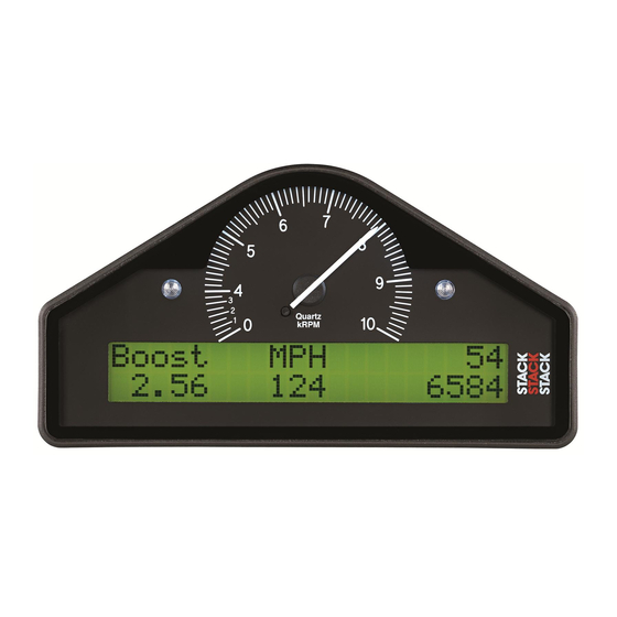
Page 9: The Display Module
STACK ST8100 Display System Appendix A. Template for the Display Module Chapter 2. Getting Started STACK ST8100 Display System Appendix A. Template for the Display Module The Display Module The Display Module consists of an analogue tachometer and a Use the template on the following page for cutting out an digital display panel. -
Page 10: Connecting The Components
STACK ST8100 Display System Chapter 2. Getting Started Chapter 2. Getting Started STACK ST8100 Display System Labels on Long Cables: Connection To Engine Speed (RPM) Symptom Possible Cause Remedy Notes Oil temperature sensor Display and Intermittent Either change Press switch 2 to see... -
Page 11: Chapter 3. Operating The Display System
STACK ST8100 Display System Chapter 2. Getting Started Chapter 3. Operating the Display System STACK ST8100 Display System Chapter 3. Operating the Display System Symptom Possible Cause Remedy Notes Display values Display too hot Ensure that This chapter takes you through the operation of the system so... - Page 12 STACK ST8100 Display System Chapter 3. Operating the Display System Chapter 2. Getting Started STACK ST8100 Display System Display Layer 1 Symptom Possible Cause Remedy Notes Display values Display too hot Ensure that Operating temperature and messages or too cold the display is is -20°C (+5°) to 70°...
- Page 13 STACK ST8100 Display System Chapter 6. Troubleshooting Chapter 3. Operating the Display System STACK ST8100 Display System Display Layer 3 Symptom Possible Cause Remedy Notes Switch 4: does Switch 4 faulty Replace switch Disconnect the switch not set or and short the leads display pop-up together.
- Page 14 STACK ST8100 Display System Chapter 3. Operating the Display System Chapter 6. Troubleshooting STACK ST8100 Display System Display Layer 5 (optional) Symptom Possible Cause Remedy Notes Peak values Gate value set Change Gate RPM Peak values only not updated too high...
-
Page 15: Peak Values
STACK ST8100 Display System Chapter 6. Troubleshooting Chapter 3. Operating the Display System STACK ST8100 Display System Peak Values (Tell Tales) Symptom Possible Cause Remedy Notes The system can display the peak values (sometimes called Fixed pressure Pressure sensor Replace sensor (‘tell-tales’) that have been recorded during a run for all the... - Page 16 P to the WT wire and pin H to both the system. The system needs to be returned to Stack every the black OT and 4-5 years for the internal battery to be changed. An alarm is WT sensor wires) triggered when the power from this battery drops below a safe level and the warning "MEM BATT"...
-
Page 17: Alarms
STACK ST8100 Display System Chapter 6. Troubleshooting Chapter 3. Operating the Display System STACK ST8100 Display System Chapter 6. Troubleshooting Alarms The Display System has built-in warnings to alert the driver when certain parameters either exceed or fall below their... - Page 18 STACK ST8100 Display System Chapter 3. Operating the Display System Chapter 5. Installing the Display System STACK ST8100 Display System Displaying an Alarm (6 inches) of heatshrink sleeving to provide additional strain relief for the cable When an alarm condition occurs, the built-in amber warning where it enters the 19-way connector.
-
Page 19: Lap Times
Occasionally an individual branch may need to be extended or significantly shortened. If the standard harness is totally unsuitable for your vehicle, contact Stack for details of custom harnesses. Provided that you have chosen suitable locations for the switches, sensors and any external warning lights that you are installing, you should not need to extend any of The most recent lap time is held in display layer 3. -
Page 20: Gear Shift Light
Drag Racers, it may be necessary to enclose the sensor in 25mm (1”) thick soft foam to obtain a ‘Clean’ signal. The Stack label indicates the direction of the G force to be measured so that a left turn will generate positive G and a right turn will generate negative G. -
Page 21: Chapter 4. Configuring The Display System
STACK ST8100 Display System Chapter 5. Installing the Display System Chapter 4. Configuring the Display System STACK ST8100 Display System Power supply to Trackside beacon Chapter 4. Configuring the Display System The beacon operates from a 12-volt DC supply. A sealed Switching the Display System on lead-acid battery with a minimum rating of 2.5 Amp/hour is... - Page 22 STACK ST8100 Display System Chapter 4. Configuring the Display System Chapter 5. Installing the Display System STACK ST8100 Display System Trackside Infra-Red Lap Beacon (optional) Gate RPM: The ST544 trackside infra-red lap beacon has a threaded socket on its base for mounting to a standard photographic tripod. It should be located as follows: •...
- Page 23 STACK ST8100 Display System Chapter 5. Installing the Display System Chapter 4. Configuring the Display System STACK ST8100 Display System Lap timing sensor (optional) Low fuel pressure: The ST543 lap timing sensor is actuated by an infra-red beacon positioned at the side of the track. The sensor is fixed to a rigid bracket mounted at a convenient position on the outside of the vehicle where it is able to detect the signals from the beacon.
- Page 24 Optional Parameters Wheel speed sensor (optional) The following parameters are only available if the Predictive The Display System may be supplied with one Stack ST670 Lap Time option is installed: proximity sensor as an optional feature. This sensor is used to...
-
Page 25: Leaving Configuration Mode
You can enable (switch on) or disable (switch off) each of the following standard types of temperature sensor: Stack ST762 alarm warnings by pressing and holding Switch 1 and then or ST764. There are two other types of optional sensor: Stack pressing Switch 2. ST760 or ST761: Note that you might change the preset value of the parameter slightly while pressing both switches. -
Page 26: Chapter 5. Installing The Display System
Chapter 5. Installing the Display System Who can install the Display System? The Display System is supplied with two Stack ST747 10 bar (145 psi) pressure sensors to measure Oil Pressure and Fuel The Display System can be installed by anyone competent in Pressure. -
Page 27: Fitting The Display Module
STACK ST8100 Display System Chapter 5. Installing the Display System Chapter 5. Installing the Display System STACK ST8100 Display System Fitting the Display Module Standard contact breaker system Connect the ES (Engine Speed) wire to the negative terminal The Display Module is fitted into a cut-out in the instrument on the coil Series Resistor Connection. -
Page 28: Switches
1. Show Peak Values vision as they need to be visible at all times. 2. Freeze speed on "HOLD" display (optional Corner Stack can supply suitable external warning lights for Speed feature only) installation in the dashboard as well as shrouded versions that can be mounted on top of the dashboard.
Need help?
Do you have a question about the ST8100 and is the answer not in the manual?
Questions and answers