Sign In
Upload
Manuals
Brands
Stack Manuals
Monitor
st8130 series
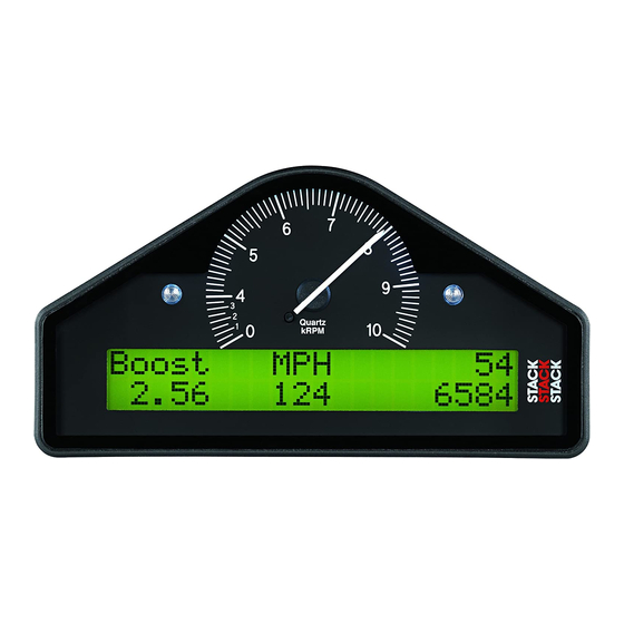
Stack st8130 series Manuals
Manuals and User Guides for Stack st8130 series. We have
2
Stack st8130 series manuals available for free PDF download: User Manual
Stack st8130 series User Manual (80 pages)
Road Car Display Systems
Brand:
Stack
| Category:
Monitor
| Size: 0 MB
Table of Contents
Registration Form
3
Edition Notice
4
Preface
5
Related Products from Stack Limited
5
Who to Contact at Stack in Case of Difficulty
6
Contents
6
Table of Contents
7
Chapter 1. Introducing the Display Systems
9
ST8130 Models
10
Fuel Level
10
Battery Voltage
10
Standard ST8130 Road Car Display System Items
12
Chapter 2. Getting Started
12
Optional ST8130 Road Car Display System Items
13
The Display Module
13
Wiring Harness
14
Connecting the Components
15
Changing the Display Layers
16
Switching the Display System on
16
Chapter 3. Operating the Display System
16
Display Layer 1
17
Display Layer 2 (ST8130 & P Variant)
17
Display Layer 2 (ST8130M Variant)
18
Display Layer 3 (ST8130 & P Variant)
18
Display Layer 3 (ST8130M Variant)
18
Display Layer 4 (ST8130 Variant)
19
Display Layer 4 (ST8130M Variant)
19
Display Layer 4 (ST8130P Variant)
19
Display Layer 5
20
Display Layer 5 (ST8130M Variant)
20
Peak Values (Tell Tales)
21
Displaying the Peak Values
22
Resetting the Peak Values
22
To Reset the Peak Values
22
Alarms
23
Peak Value Memory
23
Clearing an Alarm
25
Displaying an Alarm
25
Showing the Last Alarm
25
Gear Shift Light
26
Lap Times
26
Resetting the Lap Time to Zero
26
Configuration Mode
27
Setting or Resetting Configuration Values
27
Chapter 4. Configuring the Display System
27
Summary of Configuration Switches
28
Switching Alarms on or off
28
Configurable Parameters
29
Air Temperature (ST8130 Variant)
30
High Oil Temperature
30
Low Fuel
30
Shift RPM
30
Fuel Level Calibration
31
Gate RPM
31
Low Fuel Pressure (ST8130P/M Variant)
31
Low Oil Pressure
31
Calculations for the ST8130 (ST492 Pulse Amplifier)
32
Wheel Pulses and Circumferences
32
Calculations for the ST8130 (ST670 Wheel Sensor)
33
Configuring the Fuel Pressure Sensor (ST8130P/M Variant)
35
Calibrating the Fuel Level
36
Tools Needed to Install the Display System
40
Who Can Install the Display System?
40
Chapter 5. Installing the Display System
40
Custom Configured Display Systems
40
Fitting the Display Module
41
Positioning the Display Module
41
Switches
42
Warning Lights
43
Engine Speed (RPM) Measurement
43
Connecting the Display System to the Ignition System
44
Standard Contact Breaker System
45
Series Resistor Connection
45
Electronic Ignition or ECU Connection
45
Pressure Sensors
46
Fitting the Pressure Sensors
46
Installing the Pressure Sensors
47
Temperature Sensors
48
Fitting the Temperature Sensors
48
Wheel Speed Sensor (ST670-Option)
49
Fitting the Wheel Speed Sensor
49
Pulse Amplifier Interface (ST492-Option)
50
Mechanical
50
Using the 'Dual-Lock' Fastener with Stack Sensors
50
To Mount a Sensor or Housing on the Vehicle
51
Electrical
52
Adjustment
52
ST492 Technical Specification
53
Fuel Tank Sender
53
Single-Wire Sender
53
Two-Wire Sender
53
Lap Timing Sensor (Optional, Std on ST8130M)
54
Trackside Infra-Red Lap Beacon (Optional, Std on ST8130M)
55
Power Supply to Trackside Beacon
56
Air Temperature Sensor (Optional on ST8130 Variant)
56
Fitting the Wiring Harness
57
Checks and Alarms
58
Wiring Labels
58
Troubleshooting
59
Template for the Display Module
70
Wiring Harness Diagram
73
Summary of Switch Functions
74
Normal Operation
74
System Configuration Mode
75
Fuel Calibration Mode
75
Index
77
Advertisement
Stack st8130 series User Manual (82 pages)
Road Car Display Systems
Brand:
Stack
| Category:
Monitor
| Size: 0 MB
Table of Contents
Preface
5
Related Products from Stack Limited
5
Who to Contact at Stack in Case of Difficulty
7
Table of Contents
11
Contents
12
Chapter 1. Introducing the Display Systems
13
ST8130 Model
14
ST8131 Model
14
How to Use this Manual
14
Chapter 2. Getting Started
16
The Display Module
17
Wiring Harness
18
Connecting the Components
19
Chapter 3. Operating the Display System
20
Switching the Display System on
20
Changing the Display Layers
20
Peak Values (Tell Tales)
23
Alarms
25
Lap Times
28
Gear Shift Light
28
Chapter 4. Configuring the Display System
29
Configuration Mode
29
Wheel Pulses and Circumferences
35
Calibrating the Fuel Level
38
Chapter 5. Installing the Display System
43
Who Can Install the Display System
43
Tools Needed to Install the Display System
43
Preconfigured Display Systems
43
Custom Configured Display Systems
43
Fitting the Display Module
44
Switches
45
Warning Lights
46
Engine Speed (RPM) Measurement
46
Connecting the Display System to the Ignition System
47
Pressure Sensor
49
Temperature Sensors
50
Wheel Speed Sensor
51
Pulse Amplifier Interface (ST492)
52
Fuel Tank Sender
55
Lap Timing Sensor (Optional)
56
Trackside Infra-Red Lap Beacon (Optional)
57
Air Temperature Sensor (Optional)
58
Wiring Harness
58
Checks and Alarms
61
Chapter 6. Troubleshooting
62
Appendix A. Template for the Display Module
73
Appendix B. Wiring Harness Diagram
76
Appendix C. Summary of Switch Functions
77
Returned Goods Form
79
Index
80
Advertisement
Related Products
Stack ST8100
Stack ST8131
Stack ST8150
Stack ST8110
Stack ST8120
Stack ST8360
Stack ST8380
Stack ST8201
Stack ST8202
Stack ST8204
Stack Categories
Accessories
Measuring Instruments
Monitor
DVR
Automobile Accessories
More Stack Manuals
Login
Sign In
OR
Sign in with Facebook
Sign in with Google
Upload manual
Upload from disk
Upload from URL