Sign In
Upload
Download
Table of Contents
Contents
Add to my manuals
Delete from my manuals
Share
URL of this page:
HTML Link:
Bookmark this page
Add
Manual will be automatically added to "My Manuals"
Print this page
×
Bookmark added
×
Added to my manuals
Manuals
Brands
Toro Manuals
Lawn and Garden Equipment
GreensPro 1240
Operator's manual
Toro GreensPro 1240 Operator's Manual
Greens roller
Hide thumbs
Also See for GreensPro 1240
:
Service manual
(186 pages)
1
2
Table Of Contents
3
4
5
6
7
8
9
10
11
12
13
14
15
16
17
18
19
20
21
22
23
24
25
26
27
28
29
30
31
32
33
34
35
36
page
of
36
Go
/
36
Contents
Table of Contents
Bookmarks
Table of Contents
Table of Contents
Safety
Safe Operating Practices
Toro Safety
Sound Power Level
Sound Pressure Level
Vibration Level
Safety and Instructional Decals
Setup
Installing the Transport Wheels
Installing the Hitch Assembly
Replacing the Warning Decal
Removing the Machine from the Pallet
Lubricating the Machine
Product Overview
Controls
Engine Controls
Specifications
Attachments/Accessories
Operation
Think Safety First
Preparing to Use the Machine
Checking the Engine-Oil Level
Checking the Hydraulic-Fluid Level
Checking the Tire Pressure
Filling the Fuel Tank
Starting and Stopping the Engine
Checking the Safety-Interlock System
Using the Hitch Lock
Transporting the Machine
Think Safety First
Operating the Machine
Operating Tips
Maintenance
Recommended Maintenance Schedule(S)
Notation for Areas of Concern
Daily Maintenance Checklist
Premaintenance Procedures
Removing the Cover
Lubrication
Lubricating the Drive-Roller Bearings and the Steering Heads
Lubricating the Linkage Pivot Points
Lubricating the Drive Chain
Engine Maintenance
Engine Oil
Servicing the Air Cleaner
Servicing the Spark Plug
Checking and Adjusting the Valve Clearance
Fuel System Maintenance
Cleaning the Sediment Cup
Drive System Maintenance
Servicing the Hydraulic Fluid
Changing the Hydraulic Fluid and Filter
Checking and Adjusting the Drive Chain Tension
Brake Maintenance
Checking and Adjusting the Parking Brake
Storage
Advertisement
Quick Links
1
Lubricating the Machine
2
Recommended Maintenance Schedule(S)
3
Changing the Hydraulic Fluid and Filter
4
Checking and Adjusting the Drive Chain Tension
Download this manual
Register at www.Toro.com.
Original Instructions (EN)
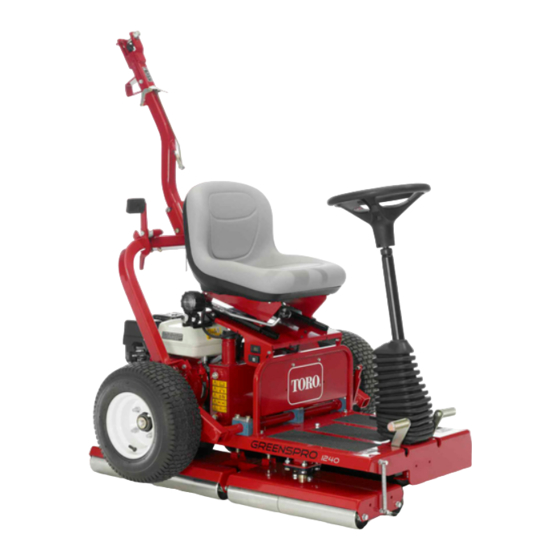
GreensPro
Model No. 44912—Serial No. 315000001 and Up
Form No. 3389-787 Rev B
™
1240 Greens Roller
*3389-787* B
Table of
Contents
Previous
Page
Next
Page
1
2
3
4
5
Advertisement
Table of Contents
Need help?
Do you have a question about the GreensPro 1240 and is the answer not in the manual?
Ask a question
Questions and answers
Related Manuals for Toro GreensPro 1240
Lawn and Garden Equipment Toro GreensPro 1240 Service Manual
(186 pages)
Lawn and Garden Equipment Toro GreensPro 1200 Installation Instructions
Greens roller (4 pages)
Lawn and Garden Equipment Toro Groundsmaster 120 Operator's Manual
Traction unit (40 pages)
Lawn and Garden Equipment Toro Workman 1100 Service Bulletin
(3 pages)
Lawn and Garden Equipment Toro ProCore 864 Operator's Manual
(40 pages)
Lawn and Garden Equipment Toro ProCore 864 Operator's Manual
(40 pages)
Lawn and Garden Equipment Toro ProCore 864 Operator's Manual
(32 pages)
Lawn and Garden Equipment Toro 125-5180 Installation Instructions
Rear roller extension kit greensmaster dpa reel mowers (2 pages)
Lawn and Garden Equipment Toro 121-5132 Installation Instructions
Steering return hose kit multi-pro 5800 turf sprayer (2 pages)
Lawn and Garden Equipment Toro 138-2995 Installation Instructions Manual
Power harness kit, groundsmaster 4500-d, 4700-d or reelmaster 7000-d traction unit (9 pages)
Lawn and Garden Equipment Toro 130-8716 Installation Instructions Manual
Hitch kit, selected groundsmaster machines (9 pages)
Lawn and Garden Equipment Toro Z-Stand 105-1621 Installation Instructions Manual
Kit, z-master 100 series (8 pages)
Lawn and Garden Equipment Toro 104-8950 Installation Instructions Manual
Ce kit for multi-pro 1200 and 1250 sprayers (9 pages)
Lawn and Garden Equipment Toro 133-0152 Installation Instructions Manual
Rear roller brush mvp kit for reelmaster 3550 series (16 pages)
Lawn and Garden Equipment Toro 135-7423 Installation Instructions Manual
Ce conversion kit 24in stand-on aerator (9 pages)
Lawn and Garden Equipment Toro 163-5940 Manual
Heavy duty spring kit titan max myride 60in zero turn riding mower (16 pages)
This manual is also suitable for:
44912
Table of Contents
Save PDF
Print
Rename the bookmark
Delete bookmark?
Delete from my manuals?
Login
Sign In
OR
Sign in with Facebook
Sign in with Google
Upload manual
Upload from disk
Upload from URL


Need help?
Do you have a question about the GreensPro 1240 and is the answer not in the manual?
Questions and answers