Table of Contents
Advertisement
Available languages
Available languages
Quick Links
Advertisement
Table of Contents

Subscribe to Our Youtube Channel
Related Manuals for Bentel Security GTCOM


Summary of Contents for Bentel Security GTCOM
- Page 1 MANUALE DI INSTALLAZIONE INSTALLATION MANUAL...
- Page 2 Questa apparecchiatura è conforme ai requisiti richiesti dalla norma CEI 79-2 2a Ed.1993 L’installazione del GTCOM deve essere effettuata a regola d’arte, in accordo con le norme vigenti. Questa apparecchiatura è stata sviluppata secondo criteri di qualità, affidabilità e prestazioni adottati dalla Bentel Security srl.
-
Page 3: Table Of Contents
Telefono ............. 21 Canali ..............23 INTRODUCTION General features ..........25 Technical Specifications ........25 Overview ............26 PARTS IDENTIFICATION OPERATING PRINCIPLES INSTALLATION Installing the GTCOM ......... 35 Terminals ............36 PROGRAMMING Customer: ............40 Telephone ............41 Channels ............43... -
Page 5: Introduzione
INTRODUZIONE Caratteristiche generali 8 canali indipendenti 8 numeri telefonici programmabili pr ogni canale Supporto dei più diffusi protocolli di comunicazione 2 distinte segnalazioni di tensione anomala Gestione della chiamata di autotest Ritardo di prima chiamata Programmazione di tutte le funzioni con Personal Computer attraverso l’interfaccia seriale RS232 Interfaccia elettronica per linea telefonica Software di programmazione in ambiente Windows... -
Page 6: Descrizione Generale
Descrizione generale Il GTCOM è un dispositivo che consente di codificare fino a 22 eventi distinti e di inviare questi codici, via telefono, ad un altro dispositivo in grado di decodificarli (stazioni di ricezione, apparecchiature di telesorveglianza e apparecchiature di televigilanza). - Page 7 In fase di progammazione per ciascuna linea di ingresso è possibile stabilire: La sequenza dei numeri telefonici da chiamare fra gli 8 che il GTCOM è in grado di memorizzare; l’ evento e quindi il codice da trasmettere ; il fronte del segnale sul quale deve avvenire l’attivazione: fronte di salita o fronte di discesa (solo per le linee d’allarme esterne e per la linea interna...
-
Page 9: Identificazione Delle Parti
IDENTIFICAZIONE DELLE PARTI Nel manuale i numeri in grassetto si riferiscono alle parti indicate nella tabella e nella figura seguente. D E S C R IZIO N E D E S C R IZIO N E 5 C o n n e t t o r e D B a 9 p o l i 1 M o rsetti per il collegam ento m a s c h i o p e r i l c o l l e g a m e n t o d e l l a l i n e a t e l e f o n i c a... -
Page 11: Descrizione Del Funzionamento11
DESCRIZIONE DEL FUNZIONAMENTO Linee di allarme esterne Il GTCOM dispone di 8 linee di allarme esterne che consentono di rilevare 16 eventi distinti; le linee di allarme esterne fanno capo ai morsetti L1,L2,L3,L4,L5,L6,L7 ed L8. Le linee di allarme esterne si attivano applicando la tensione di alimentazione (12 V circa) oppure la massa, ai morsetti L1..L8. - Page 12 “Antisabotaggio”, l’innesco avverrà all’ apertura dei morsetti “A.S.” se si inserisce il codice evento nel campo “Ripristino Antisabotaggio”, l’innesco Ø avverrà cortocircuitando i morsetti “A.S.” Usare questa linea per rilevare tentativi di sabotaggio portati contro il conteni- tore del GTCOM.
- Page 13 Batteria Bassa <11V La linea interna in questione serve per rilevare una condizione di alimentazione anomala: se la tensione di alimentazione del GTCOM ( quella presente tra i morsetti Ø [+12V] e [-] scende sotto il valore di 11,3 V, viene trasmesso il codice evento relativo alla descrizione “Batteria bassa 11 Vdc”.
-
Page 15: Installazione
In tal caso, tenere presente l’ingombro del GTCOM (profilo tratteggiato) e il passo dei fori di fissaggio visualizzati in figura 4. Non fissare il GTCOM a diretto contatto con il fondo del contenitore onde evitare cortocircuiti accidentali, ma usare piuttosto dei distanziatori plastici come mostrato in figura 4. -
Page 16: Descrizione Morsetti
(vedere capitolo programmazione) Linea telefonica esterna. Collegare a questi morsetti la linea telefonica L.E. esterna. GTCOM deve essere collegato a monte di altri eventuali apparecchi telefonici presenti sulla stessa linea (vedere figura 5) L.I. Linea telefonica interna. Usare questi morsetti per il collegamento di altri... - Page 17 COM. 2 COM. 1 Adattatore (art. ADSER/9M25F) Cavo seriale (art. CVSER/9F9F) GTCOM Scambio libero centrale antifurto Alimentazione 12 V , 70 mA Scambio libero centrale antincendio Pulsante Scambio antisabotaggio libero N.C. radioricevitore Figura 5 Schema di collegamento. INSTALLAZIONE...
-
Page 19: Programmazione
PROGRAMMAZIONE La programmazione del GTCOM si effettua tramite PC con l’ ausilio di un appo- sito programma “GTCOM” contenuto nel pacchetto software Bentel Security Suite. Per il collegamento del GTCOM al PC, usare il cavo seriale fornito su richiesta: articolo CVSER9F9F. -
Page 20: Cliente
E’ il numero di telefono al quale è collegato il GTCOM che si sta programmando. Telefono Impianto Il campo revisione firmware mostra la revisione del firmware istallato sul GTCOM Revisione Firmware E’... -
Page 21: Telefono
Telefono In questa pagina si definisce l’agenda degli 8 numeri telefonici che la centrale potrà utilizzare ed inoltre si programmano le opzioni telefoniche. Identifica il numero telefonico programmato nella casella adiacente I numeri telefonici inseriti in questo campo potranno essere selezionati dal comunicatore digitale;... - Page 22 Vedere figura 3). Disabilita Normalmente GTCOM controlla la presenza del tono di linea prima di seleziona- Controllo Toni re un numero telefonico e se non lo rileva riaggancia per poi effettuare un altro tentativo.
-
Page 23: Canali
Canali Questa pagina è il cuore del GTCOM. In questa pagina si stabiliscono infatti Descrizione quali azioni telefoniche attivare in corrispondenza degli eventi che la centrale è in grado di riconoscere Di seguito è riportata una tabella nelle cui righe sono riportati gli eventi che la centrale riconosce. - Page 24 CLASSIFICAZIONE CODICI EVENTO I codici evento sono stati raggruppati in accordo al tipo di evento come descritto di seguito Allarmi Medicali - 1AA 153 Perdita di Temperatura 334 Avaria Repeater Controllo Accessi - 2A 154 Fuoriuscita d’acqua 335 Fine carta stampante locale 1AA Medical 421 Accesso negato 155 Rottura lamina...
-
Page 25: Introduction
INTRODUCTION General features 8 independent channels 8 programmable telephone numbers per channel Supports the most widely used protocols 2 distinct signals for Power Trouble Auto-test call First call delay Fully programmable from PC via RS232 Serial Interface PSTN Line Interface Software Application (runs under Windows) Technical Specifications Power Supply... -
Page 26: Overview
Overview The GTCOM supports the most widely used protocols, and can encode up to 22 events for transmission, via the PSTN line, to Decoding receiver systems (Central Stations, etc.). PROTECTED ZONE CENTRAL STATION PSTN decoding event line encoding This device has been designed for remote supervision of Burglar and Fire control systems, and similar security and surveillance applications. - Page 27 User Code (to be assigned to each Telephone number) Reporting Protocol Dialling mode (DTMF or Pulse) The GTCOM can be programmed via the GTCOM Software Application, from Bentel Security Suite Software Package (runs under Windows 3.1 or higher). The optional Software Application, with graphic interface, provides a fast trouble-free way of programming the device.
-
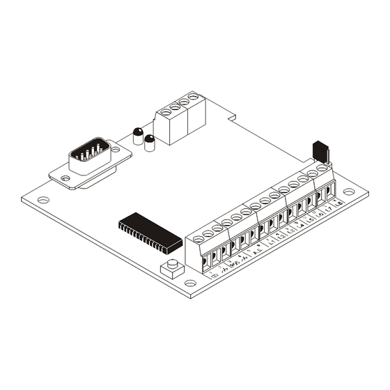
Page 29: Parts Identification
3 R e s e t button 7 R e d L E D : Operating 4 P u l l u p o r p u l l d o wn ( J u m per) Figure 1: GTCOM Components PARTS IDENTIFICATION... -
Page 31: Operating Principles
OPERATING PRINCIPLES External Alarm Lines The GTCOM has 8 External Alarm lines that allow detection of 16 events. The 8 External Alarm lines are connected respectively to terminals L1,L2,L3,L4,L5,L6,L7 and L8. The External Alarm lines are activated by applying the power supply voltage (approx. - Page 32 ‘Tamper’ field, activation will occur when the ‘A.S.’ terminals open. Ø if the event code is entered in the ‘Reset Tamper’ field, activation will occur when the ‘A.S.’ terminals open are short-circuited. Use this line to detect Tamper on the GTCOM casing.
- Page 33 (between terminals [+12V] and [-]) drops below 11.3 V, Ø the GTCOM will transmit the ‘ L ow Battery 11 Vdc’ event code. It will transmit the ‘Reset Low Battery 11 V’ event code, as soon as the supply voltage is restored (value >...
-
Page 35: Installation
INSTALLATION Installing the GTCOM The GTCOM can be mounted inside its own box, or inside the security system casing (space allowing). Figure 4 shows the exact size (refer to the dashed outline), and attachment procedure. Do not attach the GTCOM to the backplate, as this may cause accidental short- circuits, use the plastic supports as per Figure 4. -
Page 36: Terminals
Supply Voltage. The GTCOM requires a 13.8 Vdc, 70 mA Max. +12V e If the supply voltage drops below 11.3 Vdc and 9 Vdc, the GTCOM will gene- rate the ‘Low Battery 11 V’ and ‘Low Battery 9 V’ events (refer to Programming). - Page 37 COM. 2 COM. 1 Adapter (art. ADSER/9M25F) Serial cable (art. CVSER/9F9F) GTCOM Burglar alarm free-voltage changeover Power supply 12 V , 70 mA Fire alarm free-voltage changeover N.C. Wireless tamper receiver button free-voltage changeover Figurae 5 Connection schematic INSTALLATION...
-
Page 39: Programming
The GTCOM can be programmed via the GTCOM Application from Bentel Security Suite Software Package.. It is possible to use the custom-made CVSER9F9F Serial Cable (accessory item) for the PC to GTCOM link, or make a serial cable, as per the following diagram. DB9 female... -
Page 40: Customer
Name name to aggregate the relevant set of data items programmed in the various pages. Customer tel.num. Enter the Telephone number that the GTCOM is connected to This field shows the GTCOM firmware release. Firmware Release Customer code Assign a 4-digit hexadecimal Customer code in this field. This code will identify the Customer univocally in the database. -
Page 41: Telephone
Select the reporting protocol for the data transmissions (Customer code and event codes). The protocol is usually assigned by the Central Station. The GTCOM supports: - ADEMCO / SILENT KNIGHT - Slow 10 baud - 4/1, 4/2 - ADEMCO / SILENT KNIGHT - Fast 14 baud - 4/1, 4/2;... - Page 42 This option is useful when the GTCOM is connected downstream to a switchboard. Pulse dialling The GTCOM is programmed to dial in DTMF (at default), as it is faster that Pulse dialling. If the PSTN line is unable to support DTMF, the Pulse Dialling option must be enabled.
-
Page 43: Channels
Channels This page is the core of the system. The programming done in this page Description determines the events that will generate the Digital Communicator actions. Refer to the Channels table below for the list of recognized events. This is the event identifier number. This is the event label. - Page 44 EVENT CODES CLASSIFICATION The Event codes have been grouped according to the type of event, as described below 153 Loss of heat 334 Repeater Failure Medical Alarms -100 Access Control -420 154 Water leakage 335 Local printer paper out 100 Medical 421 Access denied 155 Foil break 336 Local printer failure...
Need help?
Do you have a question about the GTCOM and is the answer not in the manual?
Questions and answers