Table of Contents
Advertisement
Advertisement
Table of Contents

Related Manuals for Dorma ESA II


Summary of Contents for Dorma ESA II
- Page 1 ESA II — Controller Commissioning, maintenance and troubleshooting instructions...
-
Page 2: Table Of Contents
Safety Technical data Door signage – sliding doors Product description ESA II system block diagram ESA II controller and interface to ESA II expansion module ESA II electrical interface diagram ESA II expansion module ESA II user interface Overview Display operation... - Page 3 TABLE OF CONTENTS — ESA II controller commissioning, maintenance and troubleshooting instructions Functional test Activation, presence and safety beam sensors Door or door and sidelight breakout Monitoring of opening and closing forces – obstruction Autolock assembly Autolock – fail safe assembly...
-
Page 4: General Information
The ESA drive motor assembly core components consist of national and local building codes. a gearmotor with encoder, ESA II controller, and DC power suppply. This assembly controls door motion of the ESA series ESA II controller commissioning: observe following standard of sliding doors. -
Page 5: Technical Data
ESA II CONTROLLER COMMISSIONING, MAINTENANCE AND TROUBLESHOOTING INSTRUCTIONS — Technical data Power supply Door functions AC power 120 VAC ± 10%, 50/60 Hz Close Fuse 6.6 amp, not replaceable Automatic Permanent open Power supply 27 VDC, 2 amperes external accessories Partial open Power consumption, max. -
Page 6: Door Signage - Sliding Doors
ESA II CONTROLLER COMMISSIONING, MAINTENANCE AND TROUBLESHOOTING INSTRUCTIONS — Door signage – sliding doors ESA sliding doors are supplied with door sign decals to alert and instruct pedestrian traffi c in operation and function of door. Method of activation determines combination of decals required. - Page 7 ESA II CONTROLLER COMMISSIONING, MAINTENANCE AND TROUBLESHOOTING INSTRUCTIONS — Automatic single slide door with signage for two-way traffic control ANNUAL COMPLIANCE INSPECTION INSPECT FOR AND COMPLIES WITH ANSI A156.19 ON DATE: _____________ by AAADM Certified Inspector Number: __________ 58” ± 5”...
-
Page 8: Product Description
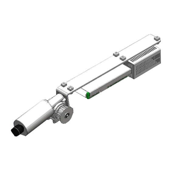
ESA II CONTROLLER COMMISSIONING, MAINTENANCE AND TROUBLESHOOTING INSTRUCTIONS — Product description ESA drive motor assembly ESA drive motor assembly DC power supply Operates from external 115 VAC, 50/60 Hz supply. Supplies +35VDC to ESA II controller. 6.6 ampere internal fuse (not replaceable) -
Page 9: Esa Ii System Block Diagram
ESA II CONTROLLER COMMISSIONING, MAINTENANCE AND TROUBLESHOOTING INSTRUCTIONS — ESA II system block diagram DORMA USA, Inc. 1 Dorma Drive, Drawer AC T: 717-336-3881 Subject to change without notice DL2842-010 05/2017 Reamstown, PA 17567 F: 717-336-2106... -
Page 10: Esa Ii Controller And Interface To Esa Ii Expansion Module
ESA II CONTROLLER COMMISSIONING, MAINTENANCE AND TROUBLESHOOTING INSTRUCTIONS — ESA II controller and interface to ESA II expansion module ESA II controller Service Interface ESA II expansion module to ESA II controller interface cable + Brn + Brn Service Interface... -
Page 11: Esa Ii Electrical Interface Diagram
ESA II CONTROLLER COMMISSIONING, MAINTENANCE AND TROUBLESHOOTING INSTRUCTIONS — ESA II electrical interface diagram Program switches CLOSE +35 VDC Power supply AUTO OPEN Green Automatic Battery Brown Permanent Open backup ESA II Interconnection EXIT ONLY LON - adapter Exit Motor... -
Page 12: Esa Ii Expansion Module
OUT 1 Outputs ESA200 header assembly OUT 2 Maximum switching Mount ESA II expansion module against back wall of header current approximately 12" [305] from end of motor gearbox. 1A @ 30VDC OUT 3 0.5A @125VAC Power MUST be removed from ESA II controller 0.3A @ 60VDC... -
Page 13: Esa Ii User Interface
ESA II CONTROLLER COMMISSIONING, MAINTENANCE AND TROUBLESHOOTING INSTRUCTIONS — 11 ESA II user interface Overview User interface SERV. button SEL. button + button – button 2 3 4 7 segment display ESA II LED 2 controller LED 1 User interface... - Page 14 ESA II CONTROLLER COMMISSIONING, MAINTENANCE AND TROUBLESHOOTING INSTRUCTIONS — 11 ESA II user interface – continued C. Accessing error codes Check controller for error codes before powering off controller. Serv. Power off resets all error codes. No error history will be displayed when controller is powered back on.
- Page 15 ESA II CONTROLLER COMMISSIONING, MAINTENANCE AND TROUBLESHOOTING INSTRUCTIONS — D. Accessing parameters Menu- Error Serv. code Menu code description display codes Error display 0 - F Parameter Sel. setting Menu Parameter code description codes 1.1 Press to access menu. code Sel.
- Page 16 ESA II CONTROLLER COMMISSIONING, MAINTENANCE AND TROUBLESHOOTING INSTRUCTIONS — 11 ESA II user interface – continued E. Parameter settings – codes Hold open time – in seconds Not available EXIT ONLY "OFF" EXIT ONLY "OFF" and "ON" >30 seconds via Dorma...
-
Page 17: Operating Instructions - Program Switch Panel
To disable setting partial open width by program switch panel. Partial open width setting can only be made via ESA II controller stores partial open width Dorma Handheld. position when main switch set to AUTO. See Appendix – Section B. -
Page 18: 115 Vac Power Connection At Header
Wire entry clamp 1/4-20 Hex head screws for jamb to header mounting Steps prior to 115 VAC power connection 3.1 Remove DC power supply plug from its socket on ESA II controller. Power P/O ESA II STOP controller... - Page 19 ESA II CONTROLLER COMMISSIONING, MAINTENANCE AND TROUBLESHOOTING INSTRUCTIONS — Electric shock hazard! 115VAC disconnect to branch DC power cable DC power supply circuit supplying power to ESA must be OFF prior to start of and during electrical wiring installation! DC power supply plug must be removed from its socket (see step 3.1).
-
Page 20: Its Door Closer And Deadstop Adjustment For Breakout
ESA II CONTROLLER COMMISSIONING, MAINTENANCE AND TROUBLESHOOTING INSTRUCTIONS — 15 ITS door closer and deadstop adjustment for breakout 1.1 ITS door closer is used to close ESA door and sidelight Latch adjustment (if a bi-part assembly) after a breakout. Sweep adjustment... - Page 21 ESA II CONTROLLER COMMISSIONING, MAINTENANCE AND TROUBLESHOOTING INSTRUCTIONS — 5.1 Open breakout assembly to 90º. Deadstop helps to prevent damage to breakout assembly by limiting its travel when breakout is Sweep range 120° - 0º operated. Adjust to 90° Latch range 7° - 0º...
-
Page 22: Installation Requirements Prior To Commissioning
ESA II CONTROLLER COMMISSIONING, MAINTENANCE AND TROUBLESHOOTING INSTRUCTIONS — 16 Installation requirements prior to commissioning 1.1 ESA door system fully installed, including glass. Reference applicable door installation instruction Customer manual. 115VAC power 1.2 When manually pushed, door runs smoothly. 1.3 Customer 115 VAC power connected to ESA header DC power supply –... -
Page 23: First Commissioning
Section 25-D for single door wiring 3.1 Manually open sliding door half way. 4.1 Turn customer 115 VAC power to ESA II ON. 4.2 Plug DC power supply plug into its receptacle on ESA II Power STOP P/O ESA II controller. -
Page 24: Perform Learning Cycle
ESA II CONTROLLER COMMISSIONING, MAINTENANCE AND TROUBLESHOOTING INSTRUCTIONS — 18 Perform learning cycle Activation sensors are disabled during learning cycle. Serv. If an interruption or fault should occur, learning cycle is terminated and must be restarted. Insure areas around door and in door travel path are free of personnel and obstacles! Sel. -
Page 25: Set Door Parameters
ESA II CONTROLLER COMMISSIONING, MAINTENANCE AND TROUBLESHOOTING INSTRUCTIONS — 19. Set door parameters Opening speed – inches/second See Section 11-D for accessing parameters. Test each parameter setting using Section 20, test of door opening cycle. 1.1 Door opening speed Set door opening speed parameter Factory default : 20 inches/sec. -
Page 26: Test Of Door Opening Cycle
ESA II CONTROLLER COMMISSIONING, MAINTENANCE AND TROUBLESHOOTING INSTRUCTIONS — 19. Set door parameters – continued 1.1 Parameter backup battery mode Backup battery mode Factory default : No backup battery installed. No backup battery installed. if backup battery installed set parameter to Emergency closing applicable value. -
Page 27: Reset Controller To Factory Settings
Power STOP Dorma handheld programmer, prior to controller reset! 21 23 1.1 Pull out DC power supply plug from ESA II controller socket. 24 25 29 30 31 1.2 Install jumpers at presence sensor terminals 21 and 23, and at 26 and 28. -
Page 28: Esa Ii Expansion Module - Dcw Address
ESA II CONTROLLER COMMISSIONING, MAINTENANCE AND TROUBLESHOOTING INSTRUCTIONS — 22 ESA II expansion module – DCW address 48 Additional functions available with expansion module using DCW address 48: Power STOP P/O ESA II controller A –Secondary closing edge sensors B –Panic closing function C –Door status contacts... - Page 29 — Panic closing function 5.1 Setting panic closing function using IN 4 input. Panic closing function must be set via Dorma Handheld. See Appendix – Section B, Special function parameter 7, Panic closing. Does not meet BHMA / ANSI 156.10.
- Page 30 ESA II CONTROLLER COMMISSIONING, MAINTENANCE AND TROUBLESHOOTING INSTRUCTIONS — 22 ESA II Expansion module – DCW address 48 – continued Door status contacts 6.1 Door status contact 1 (OUT-1): OUT1 OUT2 OUT3 OUT4 Default is "Door open". Relay contact is closed when door:...
- Page 31 ESA II CONTROLLER COMMISSIONING, MAINTENANCE AND TROUBLESHOOTING INSTRUCTIONS — 23 ESA II Expansion module – DCW address 49 – continued Airlock function 3.1 Disabling airlock function (IN-3) As soon as airlock function is activated while door is still closed, both internal and external activation sensors are blocked.
- Page 32 ESA II CONTROLLER COMMISSIONING, MAINTENANCE AND TROUBLESHOOTING INSTRUCTIONS — 24 Functional test Activation, presence and safety beam sensors Reference Appendix, Section A A156.10_sensors – sliding doors. CLOSE AUTO OPEN O II 1.1 Set program panel switches to following positions: EXIT ONLY ...
- Page 33 ESA II CONTROLLER COMMISSIONING, MAINTENANCE AND TROUBLESHOOTING INSTRUCTIONS — 24 Functional test – continued Door or door and sidelight breakout Purpose of test: verify door and panel breakout operation. CLOSE AUTO OPEN O II 1.1 Set program panel switches to following positions: ...
- Page 34 For these tests a door pressu ESA II controller Power STOP 1.1 For these test, bypass presence sensor inputs by installing jumpers at ESA II controller terminals 21 and 23, and at terminals 26 and 28. 21 23 29 30 31 24 25...
- Page 35 ESA II CONTROLLER COMMISSIONING, MAINTENANCE AND TROUBLESHOOTING INSTRUCTIONS — 23 Functional test – continued Autolock assembly Bipart door shown Autolock assembly Autolock assembly Double hook Autolock carrier bracket 1.1 Locking parameter set to , bistable with feedback Door locking device type contact.
- Page 36 ESA II CONTROLLER COMMISSIONING, MAINTENANCE AND TROUBLESHOOTING INSTRUCTIONS — 24 Functional test – continued Autolock – fail safe assembly 1.1 Locking parameter set to , monostable fail safe Door carriage locking device type with feedback contact. No locking device 1.2 Program panel main switch set to AUTO.
- Page 37 ESA II CONTROLLER COMMISSIONING, MAINTENANCE AND TROUBLESHOOTING INSTRUCTIONS — Night-bank contact (optional) 1.1 Program panel main switch – set to CLOSE. If main switch was in OPEN postion, door will immediately close at set closing speed. CLOSE CLOSE AUTO OPEN...
- Page 38 DC power supply Charge can be confi rmed by removing DC power supply plug (34-36), then installing battery backup plug (37, 38). ESA II controller should power up normally. Customer 3.1 Simulated loss of 115 VAC power will be accomplished...
- Page 39 ESA II CONTROLLER COMMISSIONING, MAINTENANCE AND TROUBLESHOOTING INSTRUCTIONS — Battery backup functional test – setting No battery Set parameter A to –No battery. See Section 11-D – accessing parameters. Program switch panel settings Door Display Main switch AUTO or CLOSE...
- Page 40 ESA II CONTROLLER COMMISSIONING, MAINTENANCE AND TROUBLESHOOTING INSTRUCTIONS — 23 Functional test – continued Battery backup functional test – setting Emergency closing Set parameter A to – Emergency closing. See Section 11-D – accessing parameters. Program switch panel settings Door...
- Page 41 ESA II CONTROLLER COMMISSIONING, MAINTENANCE AND TROUBLESHOOTING INSTRUCTIONS — Battery backup functional test – setting Emergency opening Set parameter A to –Emergency opening. See Section 11-D – accessing parameters. Program switch panel settings Door Display Main switch AUTO or CLOSE...
- Page 42 ESA II CONTROLLER COMMISSIONING, MAINTENANCE AND TROUBLESHOOTING INSTRUCTIONS — 25 Wiring diagrams Program switch panel CLOSE AUTO OPEN O II EXIT ONLY PARTIAL OPEN ESA II controller Term. Wire Switch Function Color Main AUTO Exit Only 1 2 3 4 5 6 7 8...
- Page 43 ESA II CONTROLLER COMMISSIONING, MAINTENANCE AND TROUBLESHOOTING INSTRUCTIONS — Autolock assembly Autolock – fail safe assembly 9 10 11 12 13 9 10 11 12 13 Cable supplied with switch Cable supplied Cable supplied with solenoid Cable supplied with switch...
- Page 44 ESA II CONTROLLER COMMISSIONING, MAINTENANCE AND TROUBLESHOOTING INSTRUCTIONS — 25 Wiring diagrams– continued Breakout switch – single door or panel Breakout switches – double doors or panels STOP STOP 30 31 32 33 30 31 32 33 ESAII ESAII controller...
- Page 45 ESA II CONTROLLER COMMISSIONING, MAINTENANCE AND TROUBLESHOOTING INSTRUCTIONS — This page left intentionally blank DORMA USA, Inc. 1 Dorma Drive, Drawer AC T: 717-336-3881 Subject to change without notice DL2842-010 05/2017 Reamstown, PA 17567 F: 717-336-2106...
- Page 46 ESA II CONTROLLER COMMISSIONING, MAINTENANCE AND TROUBLESHOOTING INSTRUCTIONS — 25 Wiring diagrams – continued G. Activation / safety sensors – BEA IXIO-DT1 Reference BEA IXIO-DT1 User Guide for sensor settings. The following changes must be Power STOP made to sensor settings:...
- Page 47 ESA II CONTROLLER COMMISSIONING, MAINTENANCE AND TROUBLESHOOTING INSTRUCTIONS — This page left intentionally blank DORMA USA, Inc. 1 Dorma Drive, Drawer AC T: 717-336-3881 Subject to change without notice DL2842-010 05/2017 Reamstown, PA 17567 F: 717-336-2106...
- Page 48 ESA II CONTROLLER COMMISSIONING, MAINTENANCE AND TROUBLESHOOTING INSTRUCTIONS — 25 Wiring diagrams – continued Activation / safety sensors – Optex X-Zone T and i-oneX T Reference Optex X-Zone T installation manual for DIP switch settings and sensor setup. Power STOP...
- Page 49 ESA II CONTROLLER COMMISSIONING, MAINTENANCE AND TROUBLESHOOTING INSTRUCTIONS — This page left intentionally blank DORMA USA, Inc. 1 Dorma Drive, Drawer AC T: 717-336-3881 Subject to change without notice DL2842-010 05/2017 Reamstown, PA 17567 F: 717-336-2106...
- Page 50 Startup and yearly system checks ESA door system must be checked, and if necessary serviced before it is commissioned for the fi rst time and thereafter as required, but at a minimum once a year by a Dorma AAADM Carrier wheel certifi ed technician.
- Page 51 (if required) Bottom holding beam (if required) Holding beam cylindrical heads Maintenance intervals – can be adjusted with Dorma Handheld. Reference: Appendix, Section B. Activation and presense sensor Diagnosis parameter 22 (Maintenance interval.): Enter a time interval in months until next scheduled maintenance.
- Page 52 ESA II CONTROLLER COMMISSIONING, MAINTENANCE AND TROUBLESHOOTING INSTRUCTIONS — 27 Troubleshooting Prior to performing any maintenance, disconnect the DC Power supply plug and the Backup battery plug from ESA II controller. Fault Possible causes Remedy Check circuit breaker supplying power ...
- Page 53 ESA II CONTROLLER COMMISSIONING, MAINTENANCE AND TROUBLESHOOTING INSTRUCTIONS — Fault Possible causes Remedy Carriage lock parameter is not set See Section 23, Functional tests. correctly. Door will not lock (carriage lock). Carriage lock wired incorrectly. See Section 25, Wiring diagrams.
- Page 54 ESA II CONTROLLER COMMISSIONING, MAINTENANCE AND TROUBLESHOOTING INSTRUCTIONS — APPENDIX A156.10_sensors – sliding doors Content references portions of ANSI / BHMA A156.10. Refer to this standard, available through BHMA, for Sliding Sliding additional information. Reference numbers in brackets door door () are paragraph numbers from the standard.
- Page 55 ESA II CONTROLLER COMMISSIONING, MAINTENANCE AND TROUBLESHOOTING INSTRUCTIONS — 3.0 (Reference 8.3.2.3) Overhead presence sensors installed on each side of sliding door opening Photoelectric beams are required Activating detection zone if presence detection zone is more 1.5 second minimum time delay than 3"...
- Page 56 ESA II CONTROLLER COMMISSIONING, MAINTENANCE AND TROUBLESHOOTING INSTRUCTIONS — APPENDIX Parameters – Dorma Handheld Parameter detail can be found on subsequent pages. Also refer to DORMA Handheld manual. Configuration parameters Driving parameters Driving parameters Special functions Ref. Ref. Ref. Ref.
- Page 57 ESA II CONTROLLER COMMISSIONING, MAINTENANCE AND TROUBLESHOOTING INSTRUCTIONS — Configuration parameters Ref- Description Settings & default Installed locking device: -No locking device -none -Bistable locking device -bistable -Bistable locking device with -bistable N.O. feedback contact (N.O.) contact -Monostable locking device, fail...
- Page 58 LIST -> 2= FST module (escape route sliding door) Displays errors that have occurred. 48 = ESA II expansion module with address OO (..) Select "ERROR" to go to error description. 49 = ESA II expansion module with address O1 Select "HELP"...
- Page 59 ESA II CONTROLLER COMMISSIONING, MAINTENANCE AND TROUBLESHOOTING INSTRUCTIONS — Diagnosis Diagnosis Ref. Description Setting Ref. Description Setting Test cycle mmyy Installation date Press "ENTER" to start test cycle. (1110 = Date of installation (month year) Test cycle is designed to detect Nov.
- Page 60 Displays input status of main program Airl. pulse input activated deactivated switch while set to CLOSE mode. Displays input status of airlock pulse at ESA II activated expansion module (addr. 49). DORMA USA, Inc. 1 Dorma Drive, Drawer AC T: 717-336-3881...
- Page 61 Displays status of respective output at activated ESA II expansion module (addr. 48). Airlock out (1 -4) deactivated Displays status of airlock output at ESA II activated expansion module (addr. 49). SST-Out 1 Displays status of relay output for breakout...
- Page 62 ESA II CONTROLLER COMMISSIONING, MAINTENANCE AND TROUBLESHOOTING INSTRUCTIONS — APPENDIX BEA Microcell One 1.1 Set operation of safety beams with DIP switches in BEA control box DIP switch settings control box: When using a single set of beams, connect beams to Beam A connector and set DIP sw.
- Page 63 ESA II CONTROLLER COMMISSIONING, MAINTENANCE AND TROUBLESHOOTING INSTRUCTIONS — This page left intentionally blank DORMA USA, Inc. 1 Dorma Drive, Drawer AC T: 717-336-3881 Subject to change without notice DL2842-010 05/2017 Reamstown, PA 17567 F: 717-336-2106...
- Page 64 DORMA USA, INC. 1 DORMA DRIVE, DRAWER AC REAMSTOWN, PA 17567 T: 717-336-3881 F: 717-336-2106...
Need help?
Do you have a question about the ESA II and is the answer not in the manual?
Questions and answers