Table of Contents
Advertisement
Quick Links
SpeechLine Digital Wireless
System Documentation
This PDF document has been created from the original interactive HTML documentation.
The PDF format does not support all HTML functions and element. That is why this PDF document might not contain all the content and interactive
elements of the HTML instruction manual.
We recommend using the complete and interactive HTML instruction manual.
You will find it in the Sennheiser Documentation App, which is available free of charge for iOS and Android. Alternatively, you can access the HTML
instruction manual in the download section of the SpeechLine Digital Wireless product page at www.sennheiser.com/speechline-dw
Sennheiser electronic GmbH & Co. KG
Am Labor 1, 30900 Wedemark, Germany, www.sennheiser.com
SpeechLine Digital Wireless - v4.0
Advertisement
Table of Contents

Related Manuals for Sennheiser SpeechLine Digital Wireless Series


Summary of Contents for Sennheiser SpeechLine Digital Wireless Series
- Page 1 We recommend using the complete and interactive HTML instruction manual. You will find it in the Sennheiser Documentation App, which is available free of charge for iOS and Android. Alternatively, you can access the HTML instruction manual in the download section of the SpeechLine Digital Wireless product page at www.sennheiser.com/speechline-dw Sennheiser electronic GmbH &...
-
Page 2: System Information
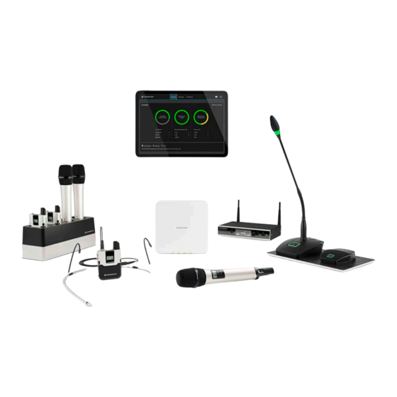
SpeechLine Digital Wireless: System Information SYSTEM INFORMATION SpeechLine Digital Wireless: System Information For more information about the individual products in the SpeechLine Digital Wireless series, see „The Products of the SpeechLine Digital Wire- less Series“. For information about the available accessories, see „Accessories“. For information about planning a complete SpeechLine Digital Wireless system, see „SpeechLine Digital Wireless: System planning“. - Page 3 SpeechLine Digital Wireless: System Information SpeechLine Digital Wireless comprises mobile transmitters (handheld or bodypack) tailored for speech applications, speech optimized condenser microphones (a microphone capsule for the handheld transmitter, a clip-on or headset microphone for the bodypack transmitter) and a rack receiver. The transmitters are powered by rechargeable lithium-ion accupacks with a battery life of more than 15 hours.
- Page 4 Focus on the spoken word Focus on the spoken word ► The spoken word is and remains the most personal and powerful instru- ment of communication we know. It allows us to convince people, to impart knowledge and to voice opinions, thoughts and views as well as emotions. That is why it is so important that none of the content is lost when audio devices such as wireless microphones and the associated receivers are used.
- Page 5 The micro- phones and the receiver of the SpeechLine Digital Wireless series are de- signed for optimum speech intelligibility, offer maximum security thanks to encrypted transmission, and provide for seamless integration into an exist- ing conference system, a media control system or a telephone system.
-
Page 6: Typical Applications
Focus on the spoken word Typical applications Excellent speech intelligibility, easy handling and convenient control are to the fore at all times, regardless of whether SpeechLine Digital Wireless is used in presentations, meetings or telephone conferences. Presentations ► In the case of a presentation held before a large audience, such as in an au- ditorium or a large conference room, it is essential that every word can be understood. - Page 7 Focus on the spoken word Meetings ► Good speech intelligibility and easy handling of the microphone system are important requirements for professional meetings. The larger the confer- ence or training room, the more helpful is an audio system which enhances speech intelligibility.
- Page 8 SpeechLine Digital Wireless system can easily be connected to an ex- isting teleconference unit such as the Sennheiser TeamConnect system. This processes the audio signals and establishes the connection to the re-...
- Page 9 Focus on the spoken word What are the features of SpeechLine Digital Wire- less? Automatic frequency management SpeechLine Digital Wireless finds free transmission frequencies reliably and fully automatically. Manual intervention is not necessary in the search for a free frequency. This means that your wireless microphone and the re- ceiver are ready for use within an extremely short time: connect them, switch them on –...
- Page 10 USB charging cable. Easy control using the Sennheiser Control Cockpit software Sennheiser Control Cockpit is the central software for easy handling, con- trol and maintenance of the entire SpeechLine Digital Wireless system. The easy-to-use Sennheiser Control Cockpit software provides a global overview of all network enabled SpeechLine Digital Wireless devices at all times.
- Page 11 Network integration enables the receiver to be remote controlled and monitored using a media control system (e.g. AMX, Cre- stron) or the Sennheiser Control Cockpit software. The antennas can either be mounted to the rear of the receiver or to the front of a rack. Antenna ca- bles of different lengths also allow mounting the antennas remotely from the receiver.
- Page 12 DSP. Due to the bidirectional communication between receiver and transmitter, all settings of the mobile transmitters can easily be made in the Sennheiser Control Cockpit. The receiver's automatic frequency management eliminates the need for manual frequency setting and the automatic interference man- agement guarantees maximum transmission reliability.
- Page 13 The Products of the SpeechLine Digital Wireless Series The handheld transmitter ► The handheld transmitter (SL Handheld DW) is ideal when several persons are speaking at the same time, such as in interviews or when queries come from the audience. You can replace the microphone capsule if necessary.
- Page 14 ► The compact, robust bodypack transmitter (SL Bodypack DW) is compati- ble with all Sennheiser headset and clip-on microphones (e.g. SL Headmic 1 or MKE 1). Thanks to the bi-directional communication between the trans- mitter and the receiver, no settings need to be adjusted on the transmitter.
- Page 15 The SL Tablestand 133-S DW is delivered with a rechargeable battery that lasts up to 10 hours. The Sennheiser Control Cockpit software can be used to monitor and con- trol the wireless table stand remotely. For information about installation and operation, see the instruction man-...
- Page 16 The SL Tablestand 153-S DW is equipped with dedicated charging status LEDs to clearly show the battery life. The Sennheiser Control Cockpit software can be used to monitor and con- trol the SL Tablestand 153-S DW remotely. For information about installation and operation, see the instruction man-...
- Page 17 The SL Boundary 114-S DW is delivered with a rechargeable battery that lasts up to 10 hours. The Sennheiser Control Cockpit software can be used to monitor and con- trol the wireless boundary microphone remotely. For information about installation and operation, see the instruction man-...
- Page 18 ► The CHG 2 charger allows you to simultaneously charge up to two trans- mitters of the SpeechLine Digital Wireless series. A bi-color LED at each charging slot provides information on the current charge status. The char- ger has universal charging slots for charging both handheld and bodypack transmitters.
- Page 19 DW. The four LEDs on each charging slot indicate the current charging status. The versatile network interface is compatible with IPv4 and IPv6 for seamless integration. The Sennheiser Control Cockpit soft- ware can be used to monitor and remotely control the settings and status messages.
- Page 20 The Products of the SpeechLine Digital Wireless Series The CHG 2W charging base ► ► The CHG 2W is a wireless charging base that provides convenient wireless charging. The CHG 2W charging base is compatible with the SL Tablestand 133-S DW, the SL Tablestand 153-S DW and the SL Boundary 114-S DW.
- Page 21 Accessories Accessories Various accessory parts are available for the SpeechLine Digital Wireless series. The clip-on and headset microphones ► ► The MKE 1 clip-on microphone is attached to clothing by means of a micro- phone clip or with adhesive tape, the SL Headmic 1 headset microphone is a head-worn microphone with an adjustable frame that wraps around the neck.
- Page 22 Accessories The AWM 2 antenna wall mount ► With the AWM 2 antenna wall mount, the antennas can be remote mounted – optimally positioned and nearly invisible – from the receiver (e.g. when the receiver has to be installed invisibly or when the receiver position is not the best antenna position for optimum reception).
- Page 23 Accessories The AWM 4 antenna wall mount ► With the AWM 4 antenna wall mount, the antennas can be remote mounted – optimally positioned and nearly invisible – from the receivers (e.g. when the receivers have to be installed invisibly or when the receiver position is not the best antenna position for optimum reception).
- Page 24 Accessories The SL PASC 2 passive antenna splitter ► ► The SL PASC 2 is a passive two-way true diversity antenna splitter/com- biner for the SpeechLine Digital Wireless microphone series. It is used to distribute the antenna signals from up to 2 SpeechLine Digital Wireless ra- dio links.
- Page 25 Accessories The SL PASC 4 passive antenna splitter ► ► The SL PASC 4 is a passive four-way true diversity antenna splitter/com- biner for the SpeechLine Digital Wireless microphone series. It is used to distribute the antenna signals from up to 4 SpeechLine Digital Wireless ra- dio links.
-
Page 26: Antenna Cables
Accessories Antenna cables • CL 5, R-SMA antenna cable for AWM 2, 5 m, article no. 505976 • CL 10, R-SMA antenna cable for AWM 2, 10 m, article no. 506263 • CL 1 PP, R-SMA antenna cable for AWM 4, 1 m, article no. 507425 •... -
Page 27: System Planning
SpeechLine Digital Wireless: System planning SYSTEM PLANNING SpeechLine Digital Wireless: System planning This section of the documentation contains information to help you with system planning: Planning Preparation: important information about country-specific fre- quency variants, correct use of transmission power and recommendations for space usage. - Page 28 SpeechLine Digital Wireless installation. Planning Tool To make planning even easier, we offer a planning tool available on the SpeechLine Digital Wireless product page at www.sennheiser.com/ speechline-dw. SpeechLine Digital Wireless product page...
- Page 29 Planning Planning At the start of planning, the following aspects are to be considered. Country-Specific Variants Check which country variant of SpeechLine Digital Wireless is suitable for your location. The following eight country variants are available. The country variant to be used determines the maximum number of links per range which can be used in the 1.9 GHz frequency band.
- Page 30 Planning -4 EU Variant: ► Latin America up to Main countries Power supply Frequency range Wireless links and regions per reception range -4 US Variant: ► Canada up to Main countries Power supply Frequency range Wireless links and regions per reception range -5 US Variant: ►...
- Page 31 Planning Number and size of the rooms ▷ Determine the number of rooms needed for the installation. Determine how each individual room is to be equipped and used. ▷ Determine the audio equipment for each room, i.e. the desired number ▷...
- Page 32 Shared use of the 1.9 GHZ frequency band When SpeechLine Digital Wireless is used in combination with other devic- es using the 1.9 GHz frequency band (e.g. Sennheiser TeamConnect Wire- less or DECT telephones), the maximum number of SpeechLine Digital Wireless links depends on the number of other devices used.
- Page 33 Planning USA, Canada, Latin America, Brazil, Taiwan ► SpeechLine Digital Wireless Links - per range (adjustable) seamless cooperation depending on spectrum used by other systems exceeds available spectrum Japan ► SpeechLine Digital Wireless Links - per range (adjustable) seamless cooperation depending on spectrum used by other systems exceeds available spectrum...
- Page 34 Planning Analysis of the environmental conditions When planning the installation of a SpeechLine Digital Wireless system, you should also carefully analyze the environmental conditions. Are there any other 1.9 GHz devices (e.g. DECT telephones or DECT access points) already installed? Observe the following aspects when planning an installation Identify the locations of DECT access points (e.g.
- Page 35 Recommendations on antenna mounting Recommendations on antenna mount- There are different factors to consider when mounting antennas. This chapter provides instructions and recommendations that you should follow when mounting antennas. Antenna setup and planning for SpeechLine Digital Wireless When planning the installation of SpeechLine Digital Wireless devices for each room, observe the following guidelines.
-
Page 36: Antenna Mounting Options
Recommendations on antenna mounting Antenna mounting options There are different options for remote mounting the antennas. We recom- mend the following four options in the specified order. >> „Option 1: Connecting the AWM 2 or AWM 4 antenna wall mount directly to the receiver(s)“... - Page 37 SL Rack Receiver DW SL Rack Receiver DW • For the AWM 2, you can use Sennheiser extension cables CL 5/10/20. • For the AWM 4, you can use Sennheiser extension cables CL 1/5/10/20 Observe the following information when using extension cables:...
- Page 38 Recommendations on antenna mounting Remote antenna distances and line of sight If you are using multiple antenna wall mounts (AWM 2/AWM 4) in one room or if individual installation and mounting of the antennas is desired, please observe the following aspects: ▷...
- Page 39 Recommendations on antenna mounting ▷ When using multiple AWM 2/AWM 4 antenna wall mounts, make sure that the distances between all antennas are equal: ► ▷ If possible, position the antennas so that there is a direct line of sight (without obstacles) between the transmitters and the antennas.
- Page 40 AWM 2 antenna wall mount. This reduces the number of antenna cables required from 4 to 2. ► Use the following Sennheiser cables for connecting the AWM 2 to the SL PASC 2: CL 5 (5 m / 16.4 ft) art.
- Page 41 AWM 2 antenna wall mount. This reduces the number of antenna cables required from 8 to 2. ► AWM 2 Use the following Sennheiser cables for connecting the AWM 2 to the SL PASC 4: CL 5 (5 m / 16.4 ft) art.
- Page 42 AWM 4 antenna wall mount. This reduces the number of antenna cables required from 16 to 4. ► Use the following Sennheiser cables for connecting the AWM 4 to the SL PASC 4: AWM 4 CL 1 PP (1 m / 3.3 ft) art.
- Page 43 Cables longer than 10 m are not recommended for this variant. This results in the following transmission power levels to be set in the menu of the receiver or simultaneously for all receivers in the Sennheiser Control Cockpit software: •...
-
Page 44: Option 3: Rack Mounting - Front
Recommendations on antenna mounting Option 3: Rack mounting - front If you wish to install the antennas together with the receivers in a rack, we recommend mounting the antennas on the front side of the rack using the GA 4 mounting kit. ▷... -
Page 45: Option 4: Rack Mounting - Rear
Recommendations on antenna mounting Option 4: Rack mounting - rear If you cannot mount the antennas at the front of the rack (option 3), you can also mount them at the rear of the receiver in the rack. When mounting, ob- serve the following information. - Page 46 Recommendations on antenna mounting Further important information on antenna usage Reflecting surfaces Electrically conducting surfaces (e.g. ceilings with metal constructions) can reflect the RF signal. ► The signal is reflected by the electrically conducting surface. At worst, the blue signal and the red reflected signal are out of phase when they reach the receiver so that the two signals cancel each other out.
- Page 47 Recommendations on antenna mounting Rule of thumb for distance from the blocking area: ► Blocking range Free range ratio 1:1 Example: ►...
- Page 48 Multi-room mode Multi-room mode SpeechLine Digital Wireless, by taking into account the installation size as well as country-specific regulations, allows to optimally use the 1.9 GHz frequency band. SpeechLine Digital Wireless offers two operating modes for different types of installation: the automatic mode with adaptive transmission power for single-room installations (Adaptive Power Mode) and the manual mode for multi-room installations, which is known as Multi-Room Mode.
- Page 49 Multi-room mode ▷ Make sure that all receivers are switched off. ▷ Switch the first receiver on. This receiver will be the master receiver. ▷ Pair a transmitter to the receiver. Only do this if necessary. The receiv- er/transmitter sets are already factory pre-paired on delivery. Wait until the status LED on both the receiver and the transmitter lights ▷...
- Page 50 Multi-room mode ▷ Perform a walk test to check the transmission power (see „Performing a walk test (reception quality)“). If necessary, re-adjust the transmission power and then repeat the ▷ walk test. ▷ The master receiver must remain switched on for the following steps. ▷...
- Page 51 SpeechLine Digital Wireless: Instruction manual INSTRUCTION MANUAL SpeechLine Digital Wireless: Instruction manual This manual provides detailed information about installation and usage of the individual products in the SpeechLine Digital Wireless series. ► SL Rack Receiver DW ► SL MCR DW ►...
- Page 52 SpeechLine Digital Wireless: Instruction manual ► SL Boundary 114-S DW ► Pairing ► Walk Test ► SL Headmic 1 ► MKE 1 ► CHG 2 ► CHG 4N ► CHG 2W...
- Page 53 SpeechLine Digital Wireless: Instruction manual ► AWM 2 ► AWM 4 ► SL PASC 2 ► SL PASC 4...
- Page 54 Network integration enables the receiver to be remote- ly controlled and monitored using a media control system (e.g. AMX, Crestron) or the Sennheiser Control Cockpit software. The antennas can either be mounted to the rear of the receiver or to the front of a rack. An- tenna cables of different lengths also allow mounting the antennas remote- ly from the receiver.
- Page 55 SL Rack Receiver DW Product overview and operating elements – front panel ► ► ► 1 PAIR button • Short-press to identify the paired transmitter. • Long-press to pair with a different transmitter. • See „Pairing“. Display panel • See „Displays on the receiver’s display panel“. Jog dial •...
- Page 56 SL Rack Receiver DW To switch the receiver off: Long-press the STANDBY button. ▷ ► LONG = OFF The display panel and the status LED go off. Status LED lights up green: A radio link to the transmitter is established. The accupack of the received transmitter is sufficiently charged.
- Page 57 SL Rack Receiver DW Product overview and connections – rear panel ► ► 7 ANT I ANT II antenna sockets (R-SMA) • Antenna inputs for connecting the supplied rod antennas • Alternatively, the antennas can be mounted using extension cables and the AWM 2 antenna wall mount or using the GA 4 mounting kit.
-
Page 58: Connecting The Receiver
SL Rack Receiver DW Connecting the receiver Connecting the receiver to the power supply system Only use the included power supply unit (NT 12-4 C or NT 2-3) to connect the receiver to the power supply system. ► ► If you use the NT 2-3 power supply unit: Slide the supplied country adapter onto the power supply unit. - Page 59 SL Rack Receiver DW ► Connect the hollow jack plug of the power supply unit to the DC IN ▷ socket of the receiver. ► ► ▷ Plug the power supply unit into the wall socket. ► Connecting an amplifier or mixing console to the receiver The unbalanced audio output (RCA) and the balanced audio output (XLR) at the rear of the receiver are connected in parallel, allowing you to simulta- neously connect two devices (e.g.
- Page 60 Sennheiser Control Cockpit software, refer to the instruction manual of the software. Please note that the host PC on which the Sennheiser Control Cockpit Service is installed must be in the same network as the devices that are to be monitored and controlled.
- Page 61 Set the Mode to Automatic in the receiver’s Network Settings menu. ▷ ▷ Ensure that the host PC on which the Sennheiser Control Cockpit ser- vice is installed is configured so that the IP address is assigned auto- matically, rather than a static configuration.
-
Page 62: Updating The Firmware
▷ Settings menu. To add the receiver in the Sennheiser Control Cockpit: Use the Add Device function in the Sennheiser Control Cockpit and ▷ enter the IP address you selected. Activate the mDNS function in the receiver’s Network Settings menu ▷... -
Page 63: Setting Up The Receiver
SL Rack Receiver DW Setting up the receiver This sections describes how to set up the receiver. You can also install the receiver in a fixed location, e.g. in a 19" rack. You can find more information about installing the receiver in a fixed location under: „Installing receivers in a rack“. - Page 64 SL Rack Receiver DW ► Connecting the rod antennas to the receiver To connect the supplied rod antennas to the receiver: ▷ Screw the two rod antennas into the receiver's two antenna sockets, ANT I II, as shown. ▷ Align the rod antennas vertically. ►...
- Page 65 SL Rack Receiver DW Installing receivers in a rack This chapter describes how to install a single receiver or two receivers side by side in a rack. You can also set up the receiver without installing it in a fixed location. You can find more information about setting up the receiver under: „Setting up the receiver“.
- Page 66 SL Rack Receiver DW GA 4 mounting kit You need the GA 4 mounting kit to install the receiver in a rack. The GA 4 mounting kit is available separately as an accessory and is also supplied with the following sets: •...
- Page 67 SL Rack Receiver DW Installing the receiver in a rack To install the receiver in a rack: Use the two supplied recessed head screws to secure the blanking ▷ plate from the GA 4 mounting kit to the mounting angle of the receiver as shown.
- Page 68 SL Rack Receiver DW Mounting the rod antennas to the front of the rack To mount the rod antennas to the front of the rack: Connect the included antenna cables to the antenna sockets at the rear ▷ of the receiver. ▷...
- Page 69 SL Rack Receiver DW Mounting the jointing plate and fastening the mounting angles (to install two receivers side by side) To fasten the mounting angles: ▷ Unscrew and remove the two recessed head screws on the outward- facing sides of the receiver. Secure the mounting angles to the outward-facing sides of the receiver ▷...
- Page 70 SL Rack Receiver DW Displays on the receiver’s display panel Home screen The home screen appears automatically after switch-on or when no button has been pressed on the receiver for a long period of time. If there is no radio link between the receiver and a transmitter, No Link ap- pears on the display panel and the display brightness is automatically dimmed.
- Page 71 Expected remaining battery life of the received transmitter • Displays the remaining battery life of the received transmitter in hours (only when the original Sennheiser BA 10, BA 30 and BA 40 ac- cupacks are used). • The remaining battery life is not displayed when batteries or re- chargeable AA size batteries are used.
- Page 72 SL Rack Receiver DW Secondary home screen When you turn the jog dial to the left from the home screen, the secondary home screen appears. ► 11Audio output level of the receiver 12Pick-up pattern of the microphone used 13Status of the low-cut filter (ON/OFF) 14Product name of the microphone capsule used...
-
Page 73: Using The Operating Menu Of The Receiver
SL Rack Receiver DW Using the operating menu of the receiver Using the buttons for navigation Press the STANDBY button •Short-press: Switches the receiver on •Long-press: Switches the receiver off Short-press the button SHORT •Navigates to the next higher level in the menu •... - Page 74 SL Rack Receiver DW The menu structure of the receiver Version: Firmware Version 2.6.10 ►...
- Page 75 SL Rack Receiver DW The Audio Settings menu The Audio Settings menu at menu level 1 allows you to adjust the following settings. Low Cut • On: The low cut filter is activated. Low-frequency noise is filtered out. • Off: The low cut filter is deactivated. Sound Profiles •...
- Page 76 SL Rack Receiver DW Display Brightness • Level: Slider for adjusting the display brightness. Mute Mode • Active: The MUTE switch of the paired transmitter is activated and can be used. • Deactivated: The MUTE switch of the paired transmitter is deactivated and cannot be used.
- Page 77 SL Rack Receiver DW The Network Settings menu The Network Settings menu at menu level 1 allows you to adjust the fol- lowing settings. Mode • Automatic: The IP address is automatically assigned using DHCP. If no DHCP server is available, the IP address is assigned by the SL Rack Re- ceiver DW itself.
- Page 78 SL Rack Receiver DW Link Name • Input of the name of the radio link between the transmitter and the re- ceiver. This name is also shown on the transmitter's display panel. Location Name • Input of the name of the room in which the receiver is set up. Serial Number •...
- Page 79 SL MCR DW The SpeechLine Multi-Channel Receiver with its 2 or 4 channels is the per- fect addition to the SpeechLine Digital Wireless series. Thanks to its unob- trusive design, the Multi-Channel Receiver can be installed quickly and easily in any room, whether on the wall or ceiling.
- Page 80 • Digital audio output (see „Connecting the receiver“) • PoE supply (Power over Ethernet) (see „Putting the receiver into op- eration“) • Configuration via the Sennheiser Control Cockpit or a media control system (see „Controlling and monitoring the receiver via the net- work“) Dante II RJ-45 socket •...
- Page 81 SL MCR DW Connecting the receiver The receiver can output analog and digital audio signals. The analog audio signal is output via the 3-pin Analog Out terminal. Digital audio signals are output via the Dante interface with two RJ-45 sockets. This interface is also used for control and configuration via the network and for Power over Ethernet supply.
- Page 82 Connecting to the network (power supply and configuration) The PoE/Ctrl RJ-45 socket (Dante I) is used to both power the receiver via Power over Ethernet and configure it using the Sennheiser Control Cock- pit software (see „Controlling and monitoring the receiver via the net- work“).
- Page 83 (4 for the SL MCR 4 DW and 2 for the SL MCR 2 DW) as well as the sum signal of the channels. You can configure in the Sennheiser Control Cockpit whether the sum signal is mixed automatically or manually (see „Controlling and monitoring the receiver via the network“).
- Page 84 The sum signal of all receiver channels is output from the Analog Out out- put. You can configure in the Sennheiser Control Cockpit whether the sum signal is mixed automatically or manually (see „Controlling and monitoring the receiver via the network“).
-
Page 85: Mounting The Receiver
SL MCR DW Mounting the receiver Safety instructions for installation Observe the following safety instructions when installing the product. ▷ The physical mounting and all electrical installations must be per- formed by a specialist. The specialist must have sufficient professional training, experience ▷... - Page 86 SL MCR DW ▷ Use the included drilling template to mark the drill holes for wall mounting. ▷ Maintain a minimum distance of 1.5 m from other walls and the ceiling. Screw the mounting frame to the wall using four suitable screws and ▷...
- Page 87 SL MCR DW Mounting the receiver on the ceiling To mount the receiver on the ceiling, you will need the mounting frame sup- plied. Screws and anchors for mounting the product to the wall are not in- cluded with delivery. Use screws and anchors that are appropriate for the particular characteristics of your wall.
- Page 88 SL MCR DW Insert the receiver into the mounting frame as shown until you hear it ▷ click into place.
- Page 89 SL MCR DW Mounting the receiver on a stand The thread in the middle of the mounting frame is suitable for mounting on a standard microphone stand with boom arm and 3/8" thread. ▷ Screw the mounting frame onto the microphone stand as shown. Insert the receiver into the mounting frame as shown until you hear it ▷...
- Page 90 SL MCR DW Mounting the receiver on a VESA mount The holes in the mounting frame are positioned 100 mm apart so that the mounting frame can be mounted on any VESA 100 mount. ▷ Screw the mounting frame onto the VESA mount as shown using four suitable screws.
-
Page 91: Putting The Receiver Into Operation
The online help contains detailed information about the functions of the Sennheiser Control Cockpit and how to configure the SL MCR DW and the network. The online help can be found on the Sennheiser Control Cock- pit product page and in the software itself. -
Page 92: Meaning Of The Status Leds
SL MCR DW Meaning of the status LEDs The four LEDs display status information for the device as a whole or for one of the two or four microphone channels. Variante: SL MCR 4 DW (4 Kanäle) Variante: SL MCR 2 DW (2 Kanäle) Kanal 4 keine Funktion Kanal 3... - Page 93 SL MCR DW All LEDs are red ▷ There is no radio link to a transmitter for any of the channels. All LEDs are flashing red ▷ A device error has occurred. Details are shown in the Control Cockpit. ▷ An error occurred while updating the device firmware.
-
Page 94: Updating The Firmware
Sennheiser Control Cockpit software. You can find more information about this procedure in the software help within the software itself or from the Sennheiser Documentation app or the download area of the Sennheiser website. The Sennheiser Control Cockpit software help... - Page 95 The SL Handheld DW The SL Handheld DW The handheld transmitter (SL Handheld DW) is ideal when several persons are speaking at the same time, such as in interviews or when queries come from the audience. You can replace the microphone capsule if necessary. The handheld transmitter is supplied with the high-quality MME 865-1 mi- crophone capsule.
-
Page 96: Product Overview
The SL Handheld DW Product overview ► Unscrewable microphone head with microphone capsule The handheld transmitter is available with or without the MME 865-1 mi- crophone capsule. The MME 865-1 has a pre-polarized condenser micro- phone capsule with super-cardioid pick-up patterns. ►... - Page 97 The SL Handheld DW To mute the handheld transmitter: Slide the MUTE switch to the position MUTE. ▷ Muted appears on the display panel of the receiver. The status LED on both the handheld transmitter and the receiver lights up yellow. ►...
- Page 98 The SL Handheld DW Displays on the display panel of the SL Handheld ► Name of the radio link • Can be entered in the Device Identification menu of the receiver (see „Using the operating menu of the receiver“). 7-step display of the accupack or battery capacity •...
- Page 99 The SL Handheld DW If you use the optional B 10 battery compartment: Insert the batteries into the B 10 battery compartment. ▷ ▷ Please observe correct polarity when inserting the batteries. ► To insert the accupack or the battery compartment: ▷...
- Page 100 The SL Handheld DW Switching the handheld transmitter on and off After switch-on, the receivers and transmitters will take approx. 10 seconds to establish the radio links. To switch the handheld transmitter on: ▷ Short-press the ON/OFF button in the direction of the transmitter body.
- Page 101 The SL Handheld DW Meaning of the status LED on the handheld transmitter lights up green: • A radio link to the receiver is established. The accupack of the handheld transmitter is sufficiently charged. flashes green: • PAIR button has been short-pressed. Paired devices are being iden- tified.
- Page 102 The SL Handheld DW Using the handheld transmitter If you touch the antenna of the handheld transmitter during transmission, the transmission range will be considerably reduced. If you cover the mi- crophone capsule during transmission, this will change the pick-up pattern of the microphone and consequently the sound.
- Page 103 The SL Bodypack DW The compact, robust SL Bodypack DW bodypack transmitter is compatible with all Sennheiser headset and clip-on microphones (e.g. SL Headmic 1 or MKE 1). Thanks to the bi-directional communication between the transmit- ter and the receiver, no settings need to be adjusted on the transmitter.
- Page 104 The SL Bodypack DW Product overview ► 1 ON/OFF button • Short-press to switch the bodypack transmitter on • Long-press to switch the bodypack transmitter off 2 MIC/LINE jack socket (3.5 mm) • for connecting the clip-on or headset microphone Status LED •...
- Page 105 The SL Bodypack DW To cancel the muting: Slide the MUTE switch to the position MIC. ▷ Antenna Display panel • See „Displays on the display panel of the SL Bodypack DW“ Catches • for releasing the accupack or the battery compartment BA 30 accupack or optional B 30 battery compartment •...
- Page 106 The SL Bodypack DW Displays on the display panel of the SL Bodypack ► ► Name of the radio link • Can be entered in the Device Identification menu of the receiver. 7-step display of the accupack or battery capacity •...
- Page 107 The SL Bodypack DW Starting up and using the bodypack transmitter Removing/inserting the accupack or the optional battery pack You can power the bodypack transmitter either with the supplied BA 30 ac- cupack or with the optional B 30 battery compartment. The accupack must be charged before the first use.
- Page 108 ► Connecting the clip-on microphone or the headset microphone to the bodypack transmitter Only connect the clip-on microphone or the headset microphone recom- mended by Sennheiser. These microphones are optimized for the bodypack transmitter. ► ▷ Connect the jack plug of the clip-on microphone or headset micro- phone to the 3.5 mm jack socket (MIC/LINE) of the bodypack transmit-...
- Page 109 The SL Bodypack DW Alternatively, you can use a 3.5 mm jack cable to connect a line source (e.g. a smartphone, tablet or laptop) to the bodypack transmit- ter. Switching the bodypack transmitter on and off After switch-on, the receivers and transmitters will take approx. 10 seconds to establish the radio links.
- Page 110 The SL Bodypack DW Meaning of the status LED on the bodypack transmitter lights up green: • A radio link to the receiver is established. The accupack of the bodypack transmitter is sufficiently charged. flashes green: • PAIR button has been short-pressed. Paired devices are being iden- tified.
- Page 111 The SL Tablestand 133-S DW is delivered with a rechargeable battery that lasts up to 10 hours. The Sennheiser Control Cockpit software can be used to monitor and con- trol the wireless table stand remotely. Return to first page of the instruction manual...
- Page 112 The SL Tablestand 133-S DW Product overview ► XLR-3 socket for connecting a goose neck microphone 2 ON/OFF button with mute function Charge level LEDs • See „Meaning of the charge level LEDs on the table stand“ Button for displaying the charge level Alignment LED •...
- Page 113 The SL Tablestand 133-S DW Starting up and using the table stand Removing/inserting the BA 40 accupack The included BA 40 accupack is used to power the table stand. The accu- pack must be charged before the first use. The accupack can either be charged with the optional CHG 2W charging base (see „The CHG 2W charging base“) or with the supplied USB cable.
- Page 114 The SL Tablestand 133-S DW Charging the table stand via USB To charge the table stand via USB: ► ▷ Connect the USB cable’s Micro-USB plug to the Micro-USB socket of the accupack. Plug the other end of the USB cable into a USB power supply unit. ▷...
- Page 115 The SL Tablestand 133-S DW Charging the table stand using the CHG 2W wireless charging base To charge the table stand using the CHG 2W charging base: ► Place the table stand on the CHG 2W charging base in the area marked. ▷...
- Page 116 The SL Tablestand 133-S DW Meaning of the charge level LEDs on the table stand The charge level LEDs indicate the charge level of the SL Tablestand 133- S DW. At 100 % charge, the SL Tablestand 133-S DW has an operating time of about 10 hours.
- Page 117 The SL Tablestand 133-S DW Connecting the goose neck microphone We recommend using the MEG 14-40 goose neck microphone. This micro- phone is optimally suited for the table stand. To connect the goose neck microphone: ► Plug the goose neck microphone into the XLR-3 socket until it locks into ▷...
- Page 118 The SL Tablestand 133-S DW Switching the table stand on/off To switch the table stand on: ► Press the ON/OFF button for 1 second. ▷ The button lights up green when a goose neck microphone is connect- To switch the table stand off: Press the ON/OFF button for 3 seconds.
- Page 119 ON/OFF button is pressed. • You can set the mute mode in the menu of the SL Rack Receiver DW or using the Sennheiser Control Cockpit.
- Page 120 The SL Tablestand 153-S DW is equipped with dedicated charging status LEDs to clearly show the battery life. The Sennheiser Control Cockpit software can be used to monitor and con- trol the SL Tablestand 153-S DW remotely. Return to first page of the instruction manual...
- Page 121 The SL Tablestand 153-S DW Product overview ► XLR-5 socket for connecting a goose neck microphone 2 ON/OFF button with mute function Charge level LEDs • See „Meaning of the charge level LEDs on the table stand“ Button for displaying the charge level Alignment LED •...
- Page 122 The SL Tablestand 153-S DW Starting up and using the table stand Removing/inserting the BA 40 accupack The included BA 40 accupack is used to power the table stand. The accu- pack must be charged before the first use. The accupack can either be charged with the optional CHG 2W charging base (see „The CHG 2W charging base“) or with the supplied USB cable.
- Page 123 The SL Tablestand 153-S DW Charging the table stand via USB To charge the table stand via USB: ► ▷ Connect the USB cable’s Micro-USB plug to the Micro-USB socket of the accupack. Plug the other end of the USB cable into a USB power supply unit. ▷...
- Page 124 The SL Tablestand 153-S DW Charging the table stand using the CHG 2W wireless charging base To charge the table stand using the CHG 2W charging base: ► Place the table stand on the CHG 2W charging base in the area marked. ▷...
- Page 125 The SL Tablestand 153-S DW Meaning of the charge level LEDs on the table stand The charge level LEDs indicate the charge level of the SL Tablestand 153- S DW. At 100 % charge, the SL Tablestand 153-S DW has an operating time of about 10 hours.
- Page 126 The SL Tablestand 153-S DW Connecting the goose neck microphone We recommend using the MEG 14-40-L-II goose neck microphone. This mi- crophone is optimally suited for the table stand. To connect the goose neck microphone: ► Plug the goose neck microphone into the XLR-3 socket until it locks into ▷...
- Page 127 The SL Tablestand 153-S DW Switching the table stand on/off To switch the table stand on: ► Press the ON/OFF button for 1 second. ▷ The button lights up green when a goose neck microphone is connect- To switch the table stand off: Press the ON/OFF button for 3 seconds.
- Page 128 ON/OFF button is pressed. • You can set the mute mode in the menu of the SL Rack Receiver DW or using the Sennheiser Control Cockpit.
- Page 129 The SL Boundary 114-S DW is delivered with a rechargeable battery that lasts up to 10 hours. The Sennheiser Control Cockpit software can be used to monitor and con- trol the wireless boundary microphone remotely. Return to first page of the instruction manual...
- Page 130 The SL Boundary 114-S DW Product overview ► 1 ON/OFF button with mute function Charge level LEDs • See „Meaning of the charge level LEDs on the boundary microphone“ Button for displaying the charge level Alignment LED • Lights up when the SL Boundary 114-S DW is correctly positioned for charging on the CHG 2W charging base BA 40 accupack •...
- Page 131 The SL Boundary 114-S DW Starting up and using the boundary microphone Removing/inserting the BA 40 accupack The included BA 40 accupack is used to power the boundary microphone. The accupack must be charged before the first use. The accupack can ei- ther be charged with the optional CHG 2W charging base (see „The CHG 2W charging base“) or with the supplied USB cable.
- Page 132 The SL Boundary 114-S DW Charging the boundary microphone via USB To charge the boundary microphone via USB: ► ▷ Connect the USB cable’s Micro-USB plug to the Micro-USB socket of the boundary microphone. ▷ Plug the other end of the USB cable into a USB power supply unit. The charge level LEDs indicate the charge level.
- Page 133 The SL Boundary 114-S DW Charging the boundary microphone using the CHG 2W wireless charging base To charge the boundary microphone using the CHG 2W charging base: ► ▷ Place the boundary microphone on the CHG 2W charging base in the area marked.
- Page 134 The SL Boundary 114-S DW Meaning of the charge level LEDs on the boundary microphone The charge level LEDs indicate the charge level of the SL Boundary 114-S DW. At 100 % charge, the SL Boundary 114-S DW has an operating time of about 10 hours.
- Page 135 ON/OFF button is pressed. • You can set the mute mode in the menu of the SL Rack Receiver DW or using the Sennheiser Control Cockpit.
- Page 136 Pairing Pairing The Pairing function enables you to identify devices that have already been paired or connect new devices. Return to first page of the instruction manual...
-
Page 137: Identifying Paired Devices
Pairing Identifying paired devices You can perform a pairing identification to see which transmitter is paired with which receiver. With the SL Rack Receiver DW, you can perform pairing identification on the device or in the Control Cockpit. With the SL MCR DW, you can only perform the pairing identification in the Control Cockpit. - Page 138 Pairing SL MCR DW ▷ Press the Find button of the desired channel of the desired device from the device list in the Control Cockpit. ► • The message This is Name appears on the transmitter's display (only SL Handheld DW and SL Bodypack DW). •...
-
Page 139: Pairing A Receiver With A Transmitter
Pairing Pairing a receiver with a transmitter To establish a new radio link between a receiver and a transmitter, proceed as follows: SL Rack Receiver DW ▷ Long-press the PAIR button of the receiver until its status LED flashes alternately green and red. Press the Pair button of the desired device from the device list in the ▷... - Page 140 Pairing If you do not update the firmware, the transmitter and the receiver will not be paired and FW mismatch appears on the display panel of the receiver. We recommend updating the receiver firmware first and then the transmit- ter firmware. SL MCR DW Press the Pair button of the desired device from the device list in the ▷...
- Page 141 Performing a walk test (reception quality) Performing a walk test (reception quali- The Walk Test menu item allows you to check the reception quality of your radio links within the operating environment. By performing a walk test, you can verify the range and coverage of the radio link. Return to first page of the instruction manual Performing a walk test with the SL MCR DW in the Control Cockpit To perform a walk test in the Control Cockpit:...
- Page 142 Performing a walk test (reception quality) ▷ Click Stop to end the walk test. If the result of the walk test is not satisfying, you can take the following re- medial measures: • If possible, position the receiver so that there is always a direct line of sight between the receiver and the paired transmitter.
- Page 143 Performing a walk test (reception quality) • If possible, position the receiver so that there is always a direct line of sight between the antennas (directly on the receiver or remotely mount- ed) and the paired transmitter. • If possible, remove obstacles between the transmitter and the anten- nas.
- Page 144 Performing a walk test (reception quality) NO LINK: If the radio link breaks down completely, the background of the display panel changes back and forth between light and dark and No Link appears on the display panel. Press the button on the receiver to end the walk test. ▷...
- Page 145 The SL Headmic 1 headset microphone The SL Headmic 1 headset microphone The SL Headmic 1 is a high-quality omni-directional condenser headset mi- crophone designed for professional “hands free” applications. Its adjust- able neckband is visually unobtrusive and very comfortable to wear. The SL Headmic 1 is available in black and beige.
- Page 146 The SL Headmic 1 headset microphone Changing the microphone position (left/right) You can wear the microphone on either the left or right side. ► The neckband has a total of five clips which are designed so that the mi- crophone boom can be worn on either side of the mouth. ATTENTION Damage to the microphone boom The microphone boom can break or be impaired in its function when you...
- Page 147 The SL Headmic 1 headset microphone capsule is fitted to the clip on the desired side of the neckband. and 4. Press the microphone boom into the two clips ▷...
-
Page 148: Adjusting The Microphone Boom And The Neckband
The SL Headmic 1 headset microphone Adjusting the microphone boom and the neckband For best possible comfort and optimum fit of the headset microphone, the neckband padding and the microphone boom have to be adjusted to prop- erly fit your head. ATTENTION Damage to the microphone boom The microphone boom can break or be impaired in its function when you... - Page 149 The SL Headmic 1 headset microphone Adjusting the neckband The neckband is adjustable in width and ensures an optimum fit. Change the length of the neckband by moving the ear hooks until a ▷ snug but comfortable fit is achieved. ►...
- Page 150 The SL Headmic 1 headset microphone Using the frequency response caps The MZC 2 frequency response cap enables you to change the sensitivity of the microphone in the presence range. The MZC 2 gives a treble boost of 4 dB. Use this cap if the microphone cannot be positioned close to the mouth, if the sound is too muffled or if you want to increase the speech in- telligibility.
-
Page 151: Using The Windshield
The SL Headmic 1 headset microphone Using the windshield The SL MZW 1 windshield reduces wind noise by 10 dB. ▷ Slide the SL MZW 1 windshield over the MZC 2 frequency response cap. ► Attaching the connection cable to clothing The MZQ 02 clip is available as an accessory. - Page 152 The SL Headmic 1 headset microphone Connecting the SL Headmic 1 to the SL Bodypack ► ▷ Connect the jack plug of the SL Headmic 1 to the 3.5 mm jack socket (MIC/LINE) of the bodypack transmitter. ▷ Lock the jack plug by screwing down the coupling ring. When the jack plug is not firmly locked, crackling noise can appear in the audio signal.
- Page 153 The MKE 1 clip-on microphone The MKE 1 clip-on microphone The MKE 1 is a high-quality, sub-miniature, sweat-resistant clip-on con- denser microphone. It features excellent sound quality and rugged design. The frequency response curve has been optimized for stage, studio and re- porting applications (ENG).
-
Page 154: Treble Boost
The MKE 1 clip-on microphone Treble boost Your microphone is supplied with two different frequency response caps. These caps allow you to adjust the treble response of the microphone. ► In addition, the large frequency response cap attenuates wind noise by ap- prox. - Page 155 The MKE 1 clip-on microphone ► Connect the jack plug of the MKE 1 to the MIC/LINE jack socket (3.5 ▷ mm) of the bodypack transmitter. Lock the jack plug by screwing down the coupling ring. ▷ When the jack plug is not firmly locked, crackling noise can appear in the audio signal.
-
Page 156: Product Overview
The CHG 2 charger The CHG 2 charger allows you to simultaneously charge up to two trans- mitters of the SpeechLine Digital Wireless series. A bi-color LED at each charging slot provides information on the current charge level. The charger has universal charging slots for charging both handheld and bodypack transmitters. - Page 157 The CHG 2 charger Connecting the CHG 2 charger to the power supply system To connect the CHG 2 charger to the power supply system: ► ▷ Connect the cable end of the power supply unit to the socket at the base of the charger.
- Page 158 The CHG 2 charger Charging the accupack in the CHG 2 charger To charge an accupack in the CHG 2 charger: ► Insert the transmitter with the accupack installed and with the ▷ charging contacts facing downwards into the charger. Make sure to insert the transmitter the correct way round: The STAND- button of the bodypack transmitter has to point in the direction of...
- Page 159 DW. The four LEDs on each charging slot indicate the current charging status. The versatile network interface is compatible with IPv4 and IPv6 for seamless integration. The Sennheiser Control Cockpit soft- ware can be used to monitor and remotely control the settings and status messages.
- Page 160 The CHG 4N charger Product overview ► Charging slots • Each suitable for both SL Handheld DW and SL Bodypack DW Charge level LEDs • See „Meaning of the charging slot status LEDs“ Power supply unit • With hollow jack plug for connection to the CHG 4N charger Power cord •...
- Page 161 The CHG 4N charger Connecting the CHG 4N charger to the power supply system To connect the CHG 4N charger to the power supply system: Connect the cable end of the power supply unit to the socket at the ▷ base of the charger.
- Page 162 The CHG 4N charger ▷ Connect one end of the power cord to the power supply unit and the other end to the wall socket. ►...
- Page 163 The CHG 4N charger Charging the accupack in the CHG 4N charger To charge an accupack in the CHG 4N charger: ► Insert the transmitter with installed accupack into one of the charger’s ▷ four charging slots. Make sure the charging contacts face downward. Make sure to insert the transmitter the correct way round.
- Page 164 Accupack charge level < 33 % An error has occurred. A corresponding error mes- sage is displayed in the Sennheiser Control Cock- pit software. The firmware of the CHG 4N is being updated. This LED status is display only when new firmware for an SL Handheld DW or SL Bodypack DW transmitter is being loaded to the CHG 4N charger.
- Page 165 You can connect the CHG 4N charger to a network using a router or switch, which allows you to monitor and control the accupack’s charge level using the Sennheiser Control Cockpit software and to modify the CHG 4N char- ger’s network configuration.
- Page 166 The CHG 4N charger is delivered with automatic IP assignment configured by default. After adding it in the Sennheiser Control Cockpit, you can re- configure it to Fixed IP. To do so, proceed as described above: „Integrating...
- Page 167 If you wish to do this, you must temporarily reconfigure the host PC on which the Sennheiser Control Cockpit is installed to automatic IP assign- ment. If the CHG 4N charger is visible in the Sennheiser Control Cockpit, you can do the IP configuration manually: ▷...
- Page 168 The CHG 4N charger ► Updating the firmware The firmware of the CHG 4N charger is updated using the Sennheiser Control Cockpit software. You can find more information about this pro- cedure in the software instruction manual in the Sennheiser Documenta- tion app or in the download area of the Sennheiser website at www.sennheiser.com/download.
- Page 169 The CHG 2W charging base The CHG 2W charging base The CHG 2W is a wireless charging base that provides convenient wireless charging. The CHG 2W charging base is compatible with the SL Tablestand 133-S DW, the SL Tablestand 153-S DW and the SL Boundary 114-S DW. Return to first page of the instruction manual Product overview ►...
- Page 170 The CHG 2W charging base Connecting the CHG 2W charging base to the power supply system To connect the CHG 2W charger to the power supply system: ► Connect the cable end of the power supply unit to the socket at the ▷...
- Page 171 The CHG 2W charging base Charging a device using the CHG 2W charging base You can use the CHG 2W charging base to charge the wireless table stands SL Tablestand 133-S DW and SL Tablestand 153-S DW as well as the wire- less boundary microphone SL Boundary 114-S DW.
- Page 172 The CHG 2W charging base Meaning of the status LEDs on the charging surfac- The two blue status LEDs on the charging surfaces provide the following status information: Flashing normally: the device is charging Flashing rapidly: excess temperature warning Flashing/flickering very rapidly: unknown device on the charger...
- Page 173 The AWM 2 antenna wall mount The AWM 2 antenna wall mount With the AWM 2 antenna wall mount, the antennas can be remote mounted – optimally positioned and nearly invisible – from the receiver (e.g. when the receiver has to be installed invisibly or when the receiver position is not the best antenna position for optimum reception).
- Page 174 The AWM 2 antenna wall mount Rod antennas • for connection to the R-SMA sockets at the top of the antenna wall mount R-SMA sockets of the antenna cables • Antenna inputs for connecting the rod antennas Antenna holes • for screwing the R-SMA sockets of the antenna cables in place Antenna housing •...
- Page 175 The AWM 2 antenna wall mount Connecting and mounting the AWM 2 Instead of the rod antennas, you can connect the optional AWM 2 antenna wall mount to the receiver. The AWM 2 is suitable for all applications where the antennas are to be positioned further away from the receiver. ▷...
- Page 176 The AWM 2 antenna wall mount ▷ Do not kink the antenna cables and, when running the cables, make sure not to bend them beyond a bend radius of 43 mm. ▷ Smaller bend radiuses can cause cracks and breaks in the cable, which may not be visible from the outside.
- Page 177 The AWM 2 antenna wall mount To mount the antenna wall mount to a microphone stand ▷ Pass the antenna cable ends fitted with the R-SMA sockets through the cable notch provided at the rear bottom edge of the antenna housing. ►...
- Page 178 The AWM 2 antenna wall mount may not be visible from the outside. This can result in bad reception quality. ▷ Screw the sockets to the antenna holes using the supplied washers and nuts. ▷ Screw the cover back to the antenna housing. Observe correct cable routing.
- Page 179 The AWM 4 antenna wall mount The AWM 4 antenna wall mount With the AWM 4 antenna wall mount, the antennas can be remote mounted – optimally positioned and nearly invisible – from the receivers (e.g. when the receivers have to be installed invisibly or when the receiver position is not the best antenna position for optimum reception).
- Page 180 The AWM 4 antenna wall mount Product overview ► Antennas Connections for Link I (receiver 1) Connections for Link II (receiver 2)
- Page 181 The AWM 4 antenna wall mount Connecting and mounting the AWM 4 Attaching the antennas Screw the four supplied rod antennas onto the housing as shown. ▷ ►...
- Page 182 You can find additional information on possible setups using the AWM 4 and general recommendations on antenna usage under „Rec- ommendations on antenna mounting“. For direct connection of the receivers to the AWM 4, we recommend using the following low-loss Sennheiser antenna cables: • CL 1 PP •...
- Page 183 The AWM 4 antenna wall mount Mounting the AWM 4 on a stand or on the wall You can either screw the AWM 4 onto a standard microphone stand or use the existing holes in the housing to mount it on the wall as shown. ►...
-
Page 184: Connectors On The Rear Of The Device
The SL PASC 2 passive antenna splitter/combiner The SL PASC 2 passive antenna splitter/ combiner The SL PASC 2 is a passive two-way true diversity antenna splitter/com- biner for the SpeechLine Digital Wireless microphone series. It is used to distribute the antenna signals from up to 2 SpeechLine Digital Wireless ra- dio links. - Page 185 The SL PASC 4 passive antenna splitter/combiner The SL PASC 4 passive antenna splitter/ combiner The SL PASC 4 is a passive four-way true diversity antenna splitter/com- biner for the SpeechLine Digital Wireless microphone series. It is used to distribute the antenna signals from up to 4 SpeechLine Digital Wireless ra- dio links.
- Page 186 The SL PASC 4 passive antenna splitter/combiner Installing antenna splitters in a rack This chapter describes how to install a single antenna splitter or two an- tenna splitters side by side in a rack. GA 4 mounting kit To install the antenna splitter in a rack, you need the GA 4 mounting kit. The GA 4 mounting kit consists of: ►...
- Page 187 The SL PASC 4 passive antenna splitter/combiner Fastening the mounting angles (to install an antenna splitter) To fasten the mounting angles: Remove the two recessed head screws on each side of the antenna ▷ splitter. ▷ Fasten the mounting angles to the sides of the antenna splitter by tight- ening the previously removed recessed head screws.
- Page 188 The SL PASC 4 passive antenna splitter/combiner Mounting the jointing plate and fastening the mounting angles (to install two antenna splitters side by side) To fasten the mounting angles: ▷ Remove the two recessed head screws on both outer-facing sides of the antenna splitters.
Need help?
Do you have a question about the SpeechLine Digital Wireless Series and is the answer not in the manual?
Questions and answers