Sennheiser SpeechLine Digital Wireless Manual
Pdf export of the original html instructions
Hide thumbs
Also See for SpeechLine Digital Wireless:
- Manual (214 pages) ,
- Instruction manual (26 pages) ,
- Quick manual (2 pages)

Related Manuals for Sennheiser SpeechLine Digital Wireless


Summary of Contents for Sennheiser SpeechLine Digital Wireless
- Page 1 SpeechLine Digital Wireless PDF export of the original HTML instructions SpeechLine Digital Wireless v4.5 | 08/2024 | 583996...
-
Page 2: Table Of Contents
1. Preface.............................7 2. System information........................8 SpeechLine Digital Wireless: System informationen............8 Focus on the spoken word..................... 10 SpeechLine Digital Wireless – the professional solution for speakers, lecturers and presenters...........................11 Typical applications......................12 What are the features of SpeechLine Digital Wireless?..........15 The Products of the SpeechLine Digital Wireless Series........... 18 The SL Rack Receiver DW receiver................ - Page 3 Antenna setup and planning for SpeechLine Digital Wireless........48 Antenna mounting options..................... 49 Option 1: Connecting the AWM 2 or AWM 4 antenna wall mount directly to the receiver(s)..........................50 Option 2: Combining multiple links to one AWM 2/AWM 4........53 Option 3: Rack mounting - front..................57 Option 4: Rack mounting - rear..................
- Page 4 Meaning of the status LEDs..................117 Updating the firmware....................123 The SL Handheld DW......................124 Product overview......................124 Displays on the display panel..................126 Removing/inserting the accupack................127 Switching the handheld transmitter on and off............128 Meaning of the status LED................... 129 Using the handheld transmitter...................
- Page 5 Muting the table stand....................171 Updating the firmware....................172 The SL Boundary 114-S DW....................173 Product overview......................173 Removing/inserting the BA 40 accupack..............175 Charging the boundary microphone................176 Meaning of the charge level LEDs................179 Switching the boundary microphone on/off ............. 180 Muting the boundary microphone................
- Page 6 Meaning of the charging slot status LEDs..............218 Controlling and monitoring the charger over the network........219 Activating power saving mode..................226 Updating the firmware....................227 The CHG 4N charger......................228 Product overview......................228 Connecting the charger to the power supply system..........230 Charging the accupack in the charger............... 232 Meaning of the charging slot status LEDs..............233 Controlling and monitoring the charger over the network........234 Activating power saving mode..................
-
Page 7: Preface
SpeechLine Digital Wireless 1. Preface PDF export of the original HTML instructions This PDF document is an automated export of an interactive set of HTML instructions. It may be the case that not all contents and interactive elements are contained in the PDF as they cannot be presented in this format. -
Page 8: System Information
For information about the available accessories, see Accessories. For information about planning a complete SpeechLine Digital Wireless system, see System planning. You can find instruction manuals for all products in the SpeechLine Digital Wireless series under Instruction manual. SpeechLine Digital Wireless is the first digital wireless microphone system designed specifically for the spoken word. - Page 9 15 hours. The accupacks can be recharged with the charger or via USB. SpeechLine Digital Wireless has an automatic frequency management feature that automatically searches for free frequencies on site, thus eliminating the need for time-consuming frequency planning in advance.
-
Page 10: Focus On The Spoken Word
Related information SpeechLine Digital Wireless – the professional solution for speakers, lecturers and presenters Typical applications What are the features of SpeechLine Digital Wireless? -
Page 11: Speechline Digital Wireless - The Professional Solution For Speakers, Lecturers And Presenters
The microphones and the receiver of the SpeechLine Digital Wireless series are designed for optimum speech intelligibility, offer maximum security thanks to encrypted transmission, and provide for seamless integration into an existing conference system, a media control system or a telephone system. -
Page 12: Typical Applications
| 2 - System information Typical applications Excellent speech intelligibility, easy handling and convenient control are to the fore at all times, regardless of whether SpeechLine Digital Wireless is used in presentations, meetings or telephone conferences. Presentations In the case of a presentation held before a large audience, such as in an auditorium or a large conference room, it is essential that every word can be understood. - Page 13 When the speaker turns in different directions, for example in order to address individual participants, he is difficult to understand in the other direction in each case. SpeechLine Digital Wireless does not restrict the freedom of movement of active speakers.
- Page 14 In modern office life, teleconferences are becoming more and more important for the cooperation of international teams. As a telephone alone can only offer inadequate speech transmission for all participants in the room, the SpeechLine Digital Wireless system can easily be connected to an existing teleconference unit such as the Sennheiser TeamConnect system.
-
Page 15: What Are The Features Of Speechline Digital Wireless
What are the features of SpeechLine Digital Wireless? Automatic frequency management SpeechLine Digital Wireless finds free transmission frequencies reliably and fully automatically. Manual intervention is not necessary in the search for a free frequency. This means that your wireless microphone and the receiver are ready for use within an extremely short time: connect them, switch them on –... - Page 16 In addition, the frequencies in this band can be used without a license. With SpeechLine Digital Wireless, you don't have to fear changes to the frequency band used which could possibly mean having to buy new audio equipment. The acquisition of a SpeechLine Digital Wireless system is a future-proof investment.
- Page 17 The Sennheiser Control Cockpit is accessible everywhere in the intranet via a web browser across all platforms. As a result, the software allows you to manage even huge setups with hundreds of devices with minimal effort.
-
Page 18: The Products Of The Speechline Digital Wireless Series
The CHG 2W charging base The SL Rack Receiver DW receiver The 9.5" rack receiver (SL Rack Receiver DW) is the core of the SpeechLine Digital Wireless system. Thanks to the bi-directional communication between the rack receiver and the transmitter, all transmitter settings can be adjusted on the receiver. The receiver's automatic... - Page 19 (e.g. AMX, Crestron) or the Sennheiser Control Cockpit software. The antenna can either be mounted to the rear of the receiver or to the front of a rack. Antenna cables of different lengths also allow mounting the antenna remotely from the receiver.
-
Page 20: Sl Multi-Channel Receiver Dw
Dante, which allows an extension of the existing setup without exchanging the DSP. Due to the bidirectional communication between receiver and transmitter, all settings of the mobile transmitters can easily be made in the Sennheiser Control Cockpit. The receiver's automatic frequency management eliminates the need for manual frequency setting and the automatic interference management guarantees maximum transmission reliability. - Page 21 | 2 - System information For information about installation and operation, see the instruction manual: Rack Receiver DW...
-
Page 22: The Handheld Transmitter
| 2 - System information The handheld transmitter The handheld transmitter (SL Handheld DW) is ideal when several persons are speaking at the same time, such as in interviews or when queries come from the audience. You can replace the microphone capsule if necessary. The handheld transmitter is supplied with the high-quality MME 865-1 microphone capsule. -
Page 23: The Bodypack Transmitter
The bodypack transmitter The compact, robust bodypack transmitter (SL Bodypack DW) is compatible with all Sennheiser headset and clip-on microphones (e.g. SL Headmic 1 or MKE 1). Thanks to the bi-directional communication between the transmitter and the receiver, no settings need to be adjusted on the transmitter. -
Page 24: The Wireless Sl Tablestand 133-S Dw
The SL Tablestand 133- S DW is delivered with a rechargeable battery that lasts up to 10 hours. The Sennheiser Control Cockpit software can be used to monitor and control the wireless table stand remotely. -
Page 25: The Wireless Sl Tablestand 153-S Dw
The SL Tablestand 153- S DW is equipped with dedicated charging status LEDs to clearly show the battery life. The Sennheiser Control Cockpit software can be used to monitor and control the SL Tablestand 153-S DW remotely. -
Page 26: The Wireless Sl Boundary 114-S Dw
The SL Boundary 114-S DW is delivered with a rechargeable battery that lasts up to 10 hours. The Sennheiser Control Cockpit software can be used to monitor and control the wireless boundary microphone remotely. -
Page 27: The Chg 2 Charger
The CHG 2 charger allows you to simultaneously charge up to two transmitters of the SpeechLine Digital Wireless series. A bi-color LED at each charging slot provides information on the current charge status. The charger has universal charging slots for charging both handheld and bodypack transmitters. -
Page 28: The Chg 2N Charger
SL Bodypack DW and the SL Handheld DW. The four LEDs on each charging slot indicate the current charging status. The versatile network interface is compatible with IPv4 and IPv6 for seamless integration. The Sennheiser Control Cockpit software can be used to monitor and remotely control the settings and status messages. -
Page 29: The Chg 4N Charger
SL Bodypack DW and the SL Handheld DW. The four LEDs on each charging slot indicate the current charging status. The versatile network interface is compatible with IPv4 and IPv6 for seamless integration. The Sennheiser Control Cockpit software can be used to monitor and remotely control the settings and status messages. -
Page 30: The Chg 2W Charging Base
| 2 - System information The CHG 2W charging base The CHG 2W is a wireless charging base that provides convenient wireless charging. The CHG 2W charging base is compatible with the SL Tablestand 133-S DW, the SL Tablestand 153-S DW and the SL Boundary 114-S DW. For information about installation and operation, see the instruction manual: CHG 2W charging base... -
Page 31: Accessories
| 2 - System information Accessories Various accessory parts are available for the SpeechLine Digital Wireless series. The clip-on and headset microphones GA 4 mounting kit The AWM 2 antenna wall mount The AWM 4 antenna wall mount The SL PASC 2 passive antenna splitter... - Page 32 | 2 - System information The MKE 1 clip-on microphone is attached to clothing by means of a microphone clip or with adhesive tape, the SL Headmic 1 headset microphone is a head-worn microphone with an adjustable frame that wraps around the neck. The unobtrusive design of the microphones lets the audience focus on the speaker.
-
Page 33: Ga 4 Mounting Kit
| 2 - System information GA 4 mounting kit You need the GA 4 mounting kit to install the receiver in a rack (see Installing receivers in a rack). The GA 4 mounting kit is available separately as an accessory and is also supplied with the following sets: •... -
Page 34: The Awm 2 Antenna Wall Mount
| 2 - System information The AWM 2 antenna wall mount With the AWM 2 antenna wall mount, the antenna can be remote mounted – optimally positioned and nearly invisible – from the receiver (e.g. when the receiver has to be installed invisibly or when the receiver position is not the best antenna position for optimum reception). -
Page 35: The Awm 4 Antenna Wall Mount
| 2 - System information The AWM 4 antenna wall mount With the AWM 4 antenna wall mount, the antenna can be remote mounted – optimally positioned and nearly invisible – from the receivers (e.g. when the receivers have to be installed invisibly or when the receiver position is not the best antenna position for optimum reception). -
Page 36: The Sl Pasc 2 Passive Antenna Splitter
SpeechLine Digital Wireless microphone series. It is used to distribute the antenna signals from up to 2 SpeechLine Digital Wireless radio links. In combination with the AWM 2 or AWM 4 remote antennas, the number of required antenna cables is reduced to a minimum. The rack receivers are connected to the SL PASC 2 using the supplied SMA-R cables. -
Page 37: The Sl Pasc 4 Passive Antenna Splitter
SpeechLine Digital Wireless microphone series. It is used to distribute the antenna signals from up to 4 SpeechLine Digital Wireless radio links. In combination with the AWM 2 or AWM 4 remote antennas, the number of required antenna cables is reduced to a minimum. The rack receivers are connected to the SL PASC 4 using the supplied SMA-R cables. -
Page 38: Antenna Cables
| 2 - System information Antenna cables • CL 1 PP, R-SMA antenna cable for AWM 2/4, 1 m, article no. 507425 • CL 5 PP, R-SMA antenna cable for AWM 2/4, 5 m, article no. 507426 • CL 10 PP, R-SMA antenna cable for AWM 2/4, 10 m, article no. 507427 •... -
Page 39: System Planning
These aspects are crucial for any project regardless of size. In this part of the documentation, we would like to offer some advice on how to proceed when planning a SpeechLine Digital Wireless installation. Planning Tool To make planning even easier, we offer a planning tool available on the SpeechLine Digital Wireless product page: sennheiser.com/speechline-wireless... -
Page 40: Planning
Analysis of the environmental conditions Country-Specific Variants Check which country variant of SpeechLine Digital Wireless is suitable for your location. The following eight country variants are available. The country variant to be used determines the maximum number of links per range which can be used in the 1.9 GHz frequency band. - Page 41 | 3 - System planning Available power supply units: • • • Wireless links per reception range: • up to 20 Variante -4: Main countries and regions: • • Canada • Latin America (without Brazil) Frequency range: • 1,920 - 1,930 MHz Available power supply units: •...
- Page 42 | 3 - System planning Wireless links per reception range: • up to 4 Variante -6: Main countries and regions: • Taiwan Frequency range: • 1,880 - 1,895 MHz Available power supply units: • Wireless links per reception range: • up to 12 Variante -7: Main countries and regions:...
-
Page 43: Number And Size Of The Rooms
| 3 - System planning Number and size of the rooms ▷ Determine the number of rooms needed for the installation. ▷ Determine how each individual room is to be equipped and used. ▷ Determine the audio equipment for each room, i.e. the desired number of SpeechLine Digital Wireless links. -
Page 44: Shared Use Of The 1.9 Ghz Frequency Band
| 3 - System planning Shared use of the 1.9 GHz frequency band When SpeechLine Digital Wireless is used in combination with other devices using the 1.9 GHz frequency band (e.g. Sennheiser TeamConnect Wireless or DECT telephones), the maximum number of SpeechLine Digital Wireless links depends on the number of other devices used. - Page 45 | 3 - System planning USA, Canada, Latin America, Brazil, Taiwan...
- Page 46 | 3 - System planning Japan...
-
Page 47: Analysis Of The Environmental Conditions
| 3 - System planning Analysis of the environmental conditions When planning the installation of a SpeechLine Digital Wireless system, you should also carefully analyze the environmental conditions. Are there any other 1.9 GHz devices (e.g. DECT telephones or DECT access points) already installed? Observe the following aspects when planning an installation ▷... -
Page 48: Recommendations On Antenna Mounting
Option 4: Rack mounting - rear Further important information on antenna usage Antenna setup and planning for SpeechLine Digital Wireless When planning the installation of SpeechLine Digital Wireless devices for each room, observe the following guidelines. ▷ Mount all SpeechLine Digital Wireless receivers together in one rack. -
Page 49: Antenna Mounting Options
| 3 - System planning Antenna mounting options There are different options for remote mounting the antennas. We recommend the following four options in the specified order. • Option 1: Connecting the AWM 2 or AWM 4 antenna wall mount directly to the receiver(s) •... -
Page 50: Option 1: Connecting The Awm 2 Or Awm 4 Antenna Wall Mount Directly To The Receiver(S)
| 3 - System planning Option 1: Connecting the AWM 2 or AWM 4 antenna wall mount directly to the receiver(s) You can connect one receiver directly to one AWM 2 antenna wall mount or you can connect two receivers directly to one AWM 4 antenna wall mount. Observe the following information when using extension cables: Signal loss due to extension cables In this scenario, using extension cables for remote antenna mounting results in a loss of... - Page 51 | 3 - System planning Remote antenna distances and line of sight If you are using multiple antenna wall mounts (AWM 2/AWM 4) in one room or if individual installation and mounting of the antennas is desired, please observe the following aspects: •...
- Page 52 | 3 - System planning If possible, group the antennas as follows: • All A antenna from the receivers’ ANT I sockets in one group according to the aforementioned requirements • All B antenna from the receivers’ ANT II sockets in one group according to the aforementioned requirements •...
-
Page 53: Option 2: Combining Multiple Links To One Awm 2/Awm 4
| 3 - System planning Option 2: Combining multiple links to one AWM 2/AWM 4 With this variant, you can use passive antenna splitters (SL PASC 2 or SL PASC 4) together with the AWM 2 or AWM 4 to combine the antenna signals from multiple receivers. This reduces the number of antenna cables required to a minimum. - Page 54 | 3 - System planning Combining up to 4 links using the AWM 2 and the SL PASC 4 The following illustration shows an example of how to combine up to 4 links with one AWM 2 antenna wall mount. This reduces the number of antenna cables required from 8 to 2. •...
- Page 55 | 3 - System planning Combining up to 8 links using the AWM 4 and two SL PASC 4 units The following illustration shows an example of how to combine up to 8 links with one AWM 4 antenna wall mount. This reduces the number of antenna cables required from 16 to 4. •...
- Page 56 Cables longer than 10 m are not recommended for this variant. This results in the following transmission power levels to be set in the menu of the receiver or simultaneously for all receivers in the Sennheiser Control Cockpit software: •...
-
Page 57: Option 3: Rack Mounting - Front
| 3 - System planning Option 3: Rack mounting - front If you wish to install the antenna together with the receivers in a rack, we recommend mounting the antenna on the front side of the rack using the GA 4 mounting kit. ▷... -
Page 58: Option 4: Rack Mounting - Rear
| 3 - System planning Option 4: Rack mounting - rear If you cannot mount the antennas at the front of the rack (option 3), you can also mount them at the rear of the receiver in the rack. When mounting, observe the following information. ▷... -
Page 59: Further Important Information On Antenna Usage
| 3 - System planning Further important information on antenna usage Reflecting surfaces Electrically conducting surfaces (e.g. ceilings with metal constructions) can reflect the RF signal. The signal is reflected by the electrically conducting surface. At worst, the blue signal and the red reflected signal are out of phase when they reach the receiver so that the two signals cancel each other out. - Page 60 | 3 - System planning Rule of thumb for distance from the blocking area: Example:...
-
Page 61: Multi-Room Mode
| 3 - System planning Multi-room mode SpeechLine Digital Wireless, by taking into account the installation size as well as country- specific regulations, allows to optimally use the 1.9 GHz frequency band. SpeechLine Digital Wireless offers two operating modes for different types of installation: the... -
Page 62: Single-Room Setup With Sl Rack Receiver Dw Only
| 3 - System planning Single-room setup with SL Rack Receiver DW only ▷ Install all receivers in one rack (see Installing receivers in a rack). ▷ Connect all cables for the receivers (see Connecting the receiver). ▷ MMount all antennas as recommended and feasible (see Recommendations on antenna mounting). -
Page 63: Single-Room Setup With Sl Multi-Channel Receiver Dw Only
| 3 - System planning Single-room setup with SL Multi-Channel Receiver DW only ▷ Install the SL Multi-Channel Receiver DW on a wall or the ceiling with the front side of the receiver facing into the room (see Mounting the receiver). -
Page 64: Single-Room Setup With Both Sl Rack Receiver Dw And Sl Multi-Channel Receiver Dw
| 3 - System planning Single-room setup with both SL Rack Receiver DW and SL Multi- Channel Receiver DW ▷ Install the SL Multi-Channel Receiver DW on a wall or the ceiling with the front side of the receiver facing into the room (see Mounting the receiver). -
Page 65: Multi-Room Mode Setup With Sl Rack Receiver Dw Only
| 3 - System planning Multi-Room Mode setup with SL Rack Receiver DW only When installing SpeechLine Digital Wireless in several rooms, it is crucial that you perform the following steps one after the other and room by room. When installing SpeechLine Digital Wireless devices in one room, all devices in all other rooms must be switched off. -
Page 66: Multi-Room Mode Setup With Sl Multi-Channel Receiver Dw Only
| 3 - System planning Multi-Room Mode setup with SL Multi-Channel Receiver DW only When installing SpeechLine Digital Wireless in several rooms, it is crucial that you perform the following steps one after the other and room by room. When installing SpeechLine Digital Wireless devices in one room, all devices in all other rooms must be switched off. - Page 67 | 3 - System planning Related information Multi-Room Mode setup with both SL Rack Receiver DW and SL Multi-Channel Receiver DW...
-
Page 68: Multi-Room Mode Setup With Both Sl Rack Receiver Dw And Sl Multi-Channel Receiver Dw
Multi-Room Mode setup with both SL Rack Receiver DW and SL Multi-Channel Receiver DW When installing SpeechLine Digital Wireless in several rooms, it is crucial that you perform the following steps one after the other and room by room. When installing SpeechLine Digital Wireless devices in one room, all devices in all other rooms must be switched off. - Page 69 | 3 - System planning ▷ Set all other multi-channel receivers to the same RF power level as the Master receiver. ▷ Then, switch on all SL Rack Receiver DW units. ➥ They will synchronize with the Master receiver. ▷ Power cycle (switch off and on again) the rack receivers.
-
Page 70: Instruction Manual
The SL PASC 4 passive antenna splitter/combiner SL Rack Receiver DW The 9.5" rack receiver (SL Rack Receiver DW) is the core of the SpeechLine Digital Wireless system. Thanks to the bi-directional communication between the rack receiver and the transmitter, all transmitter settings can be adjusted on the receiver. The receiver's automatic frequency management eliminates the need for manual frequency setting and the automatic interference management guarantees maximum transmission reliability. -
Page 71: Product Overview And Operating Elements - Front Panel
| 4 - Instruction manual Related information Product overview and operating elements – front panel Product overview and connections – rear panel Meaning of the Status LED Connecting the receiver Controlling and monitoring the receiver via the network Updating the firmware Setting up the receiver Installing receivers in a rack Switching the receiver on and off... - Page 72 | 4 - Instruction manual 3 Jog dial • Turn to navigate through the menu, to change settings or to change from the home screen to the secondary home screen. • Press to open the menu or to confirm the entry or selection. 4 ESC button •...
-
Page 73: Product Overview And Connections - Rear Panel
| 4 - Instruction manual Product overview and connections – rear panel 7 ANT I and ANT II antenna sockets (R-SMA) • Antenna inputs for connecting the supplied rod antenna • Alternatively, the antenna can be mounted using extension cables and the AWM 2 antenna wall mount or using the GA 4 mounting kit. - Page 74 | 4 - Instruction manual 11 AF OUT BAL socket (XLR-3) • Balanced audio output (XLR) • Connecting an amplifier or mixing console to the receiver 12 LAN Ethernet socket • For connecting to a router or a switch in order to simultaneously control and monitor several devices in the network.
-
Page 75: Meaning Of The Status Led
| 4 - Instruction manual Meaning of the Status LED lights up green A radio link to the transmitter is established. The accupack of the received transmitter is sufficiently charged. flashes green The PAIR button has been short-pressed. Paired devices are being identified. flashes alternately green and red The PAIR button has been long-pressed. - Page 76 | 4 - Instruction manual lights up yellow The received transmitter has been muted with the MUTE switch. In addition, Muted is displayed on the display panel. flashes yellow The firmware is being updated. lights up red No radio link to a transmitter. In addition, the background of the display panel changes back and forth between light and dark and No Link appears on the display panel.
- Page 77 | 4 - Instruction manual flashes red The accupack capacity of the received transmitter is only sufficient for max. 30 minutes of operation.
-
Page 78: Connecting The Receiver
| 4 - Instruction manual Connecting the receiver Connecting the receiver to the power supply system Only use the included power supply unit (NT 12‑4 C or NT 2‑3) to connect the receiver to the power supply system. If you use the NT 2-3 power supply unit: ▷... - Page 79 | 4 - Instruction manual ▷ Connect the hollow jack plug of the power supply unit to the DC IN socket of the receiver. ▷ Plug the power supply unit into the wall socket.
- Page 80 | 4 - Instruction manual Connecting an amplifier or mixing console to the receiver The unbalanced audio output (RCA) and the balanced audio output (XLR) at the rear of the receiver are connected in parallel, allowing you to simultaneously connect two devices (e.g. amplifier and mixing console) to the receiver. ▷...
-
Page 81: Controlling And Monitoring The Receiver Via The Network
Cockpit software, refer to the instruction manual of the software. Please note that the host PC on which the Sennheiser Control Cockpit Service is installed must be in the same network as the devices that are to be monitored and controlled. - Page 82 Set the Mode to Automatic in the receiver’s Network Settings menu. ▷ Ensure that the host PC on which the Sennheiser Control Cockpit service is installed is configured so that the IP address is assigned automatically, rather than a static configuration.
-
Page 83: Updating The Firmware
| 4 - Instruction manual Updating the firmware The firmware of the receiver is updated using the Sennheiser Control Cockpit software. You can find more information about this procedure in the software help within the software itself or the download area of the Sennheiser website. -
Page 84: Setting Up The Receiver
| 4 - Instruction manual Setting up the receiver This sections describes how to set up the receiver. You can also install the receiver in a fixed location, e.g. in a 19" rack. You can find more information about installing the receiver in a fixed location under: Installing receivers in a rack. - Page 85 | 4 - Instruction manual Attaching the mounting angles The mounting angles are designed to help protect the operating elements from damage or deformation, e.g. if the receiver is dropped. We therefore recommend always attaching the mounting angles, even if you do not want to mount the receiver into a rack.
- Page 86 | 4 - Instruction manual Connecting the AWM 2 / AWM 4 remote antenna to the receiver Instead of the supplied rod antenna, you can also connect a remote antenna to the receiver. For more information, see AWM 2 / AWM 4 remote antennas.
-
Page 87: Installing Receivers In A Rack
| 4 - Instruction manual Installing receivers in a rack This chapter describes how to install a single receiver or two receivers side by side in a rack. You can also set up the receiver without installing it in a fixed location. You can find more information about setting up the receiver under: Setting up the receiver. - Page 88 | 4 - Instruction manual Installing the receiver in a rack ▷ Use the two supplied recessed head screws to secure the blanking plate from the GA 4 mounting kit to the mounting angle of the receiver as shown. ➥ Make sure to use the correct side (the one with the round holes) of the blanking plate to secure it to the mounting angle.
- Page 89 | 4 - Instruction manual Mounting the jointing plate and fastening the mounting angles (to install two receivers side by side) ▷ Unscrew and remove the two recessed head screws on the outward-facing sides of the receiver. ▷ Secure the mounting angles to the outward-facing sides of the receiver using the previously removed recessed head screws.
-
Page 90: Switching The Receiver On And Off
| 4 - Instruction manual Switching the receiver on and off To switch the receiver on: ▷ Short-press the STANDBY button. ➥ The display panel first shows a logo and then the home screen appears. The status LED indicates the current status of the receiver. The radio link to the last paired transmitter is established automatically as soon as the transmitter is switched on. -
Page 91: Displays On The Receiver's Display Panel
| 4 - Instruction manual Displays on the receiver’s display panel Home Screen The home screen appears automatically after switch-on or when no button has been pressed on the receiver for a long period of time. If there is no radio link between the receiver and a transmitter, No Link appears on the display panel and the display brightness is automatically dimmed. - Page 92 | 4 - Instruction manual 4 Secondary home screen • The secondary home screen appears when you turn the jog dial to the left. • The above shown home screen appears again after 10 seconds or when you turn the jog dial to the right. 5 6-step display for the RF signal level •...
- Page 93 9 Expected remaining battery life of the received transmitter • Displays the remaining battery life of the received transmitter in hours (only when the original Sennheiser BA 10, BA 30 and BA 40 accupacks are used). • The remaining battery life is not displayed when batteries or rechargeable AA size batteries are used.
-
Page 94: Using The Operating Menu Of The Receiver
| 4 - Instruction manual Using the operating menu of the receiver Using the buttons for navigation Press the STANDBY button • Short-press: Switches the receiver on • Long-press: Switches the receiver off Short-press the ESC button • Navigates to the next higher level in the menu •... - Page 95 | 4 - Instruction manual The menu structure of the receiver Version: Firmware Version 2.6.10 The Audio Settings menu The Audio Settings menu at menu level 1 allows you to adjust the following settings. Low Cut • On: The low cut filter is activated. Low-frequency noise is filtered out. •...
- Page 96 | 4 - Instruction manual Sound Profiles • Off: No sound profile is activated. • Female Speech: Recommended sound profile for female speakers. • Male Speech: Recommended sound profile for male speakers. • Media: Recommended sound profile for other audio devices. •...
- Page 97 | 4 - Instruction manual Auto Lock • On: The automatic lock mode is activated. If no button is actuated on the receiver for approx. 10 seconds, the lock mode is automatically activated. • Long-press the jog dial to temporarily deactivate the lock mode. •...
- Page 98 The Help menu at menu level 1 allows you to adjust the following settings. Product Information • QR Code with link to the product page of SpeechLine Digital Wireless. User Manual • QR Code with link to download the instruction manual.
-
Page 99: Sl Mcr Dw
The SpeechLine Multi-Channel Receiver with its 2 or 4 channels is the perfect addition to the SpeechLine Digital Wireless series. Thanks to its unobtrusive design, the Multi-Channel Receiver can be installed quickly and easily in any room, whether on the wall or ceiling. - Page 100 PoE supply (Power over Ethernet) (Power over Ethernet) (see Putting the receiver into operation) • Configuration via the Sennheiser Control Cockpit or a media control systemg (see Controlling and monitoring the receiver via the network) 5 Dante II RJ-45 socket •...
-
Page 101: Directivity Of The Integrated Antennas
| 4 - Instruction manual Directivity of the integrated antennas The receiver has eight integrated antennas. The directivity of the antennas is as follows. Directivity: total... - Page 102 | 4 - Instruction manual Polar diagram: total Polar diagram: horizontal...
- Page 103 | 4 - Instruction manual Polar diagram: vertical...
-
Page 104: Connecting The Receiver
| 4 - Instruction manual Connecting the receiver The receiver can output analog and digital audio signals. The analog audio signal is output via the 3-pin Analog Out terminal. Digital audio signals are output via the Dante interface with two RJ-45 sockets. This interface is also used for control and configuration via the network and for Power over Ethernet supply. - Page 105 Connecting to the network (power supply and configuration) The PoE/Ctrl RJ-45 socket (Dante I) is used to both power the receiver via Power over Ethernet and configure it using the Sennheiser Control Cockpit software (see Controlling and monitoring the receiver via the network).
- Page 106 SL MCR 4 DW and 2 for the SL MCR 2 DW) as well as the sum signal of the channels. You can configure in the Sennheiser Control Cockpit whether the sum signal is mixed automatically or manually (see...
- Page 107 | 4 - Instruction manual You can configure in the Sennheiser Control Cockpit whether the sum signal is mixed automatically or manually (see Controlling and monitoring the receiver via the network).
-
Page 108: Mounting The Receiver
| 4 - Instruction manual Mounting the receiver Safety instructions for installation Observe the following safety instructions when installing the product. ▷ The physical mounting and all electrical installations must be performed by a specialist. ▷ The specialist must have sufficient professional training, experience and knowledge of applicable provisions, regulations and standards to be able to properly assess the work assigned to them, identify possible hazards and take appropriate safety measures. - Page 109 | 4 - Instruction manual Screws and anchors for mounting the product to the wall are not included with delivery. Use screws and anchors that are appropriate for the particular characteristics of your wall. ▷ Use the included drilling template to mark the drill holes for wall mounting. ▷...
- Page 110 | 4 - Instruction manual NOTICE Damage to the receiver due to incorrect mounting. The receiver may fall out and be damaged. ▷ The top marking on the mounting frame must not point downwards. ▷ Insert the receiver into the mounting frame as shown until you hear it click into place.
- Page 111 | 4 - Instruction manual Mounting the receiver on the ceiling To mount the receiver on the ceiling, you will need the mounting frame supplied. Screws and anchors for mounting the product to the wall are not included with delivery. Use screws and anchors that are appropriate for the particular characteristics of your wall.
- Page 112 | 4 - Instruction manual ▷ Screw the mounting frame to the ceiling using four suitable screws and anchors. ▷ Insert the receiver into the mounting frame as shown until you hear it click into place.
- Page 113 | 4 - Instruction manual Mounting the receiver on a stand The thread in the middle of the mounting frame is suitable for mounting on a standard microphone stand with boom arm and 3/8" thread. CAUTION Danger from falling objects If you mount the receiver improperly on the stand, the stand and receiver may tip over.
- Page 114 | 4 - Instruction manual Mounting the receiver on a VESA mount The holes in the mounting frame are positioned 100 mm apart so that the mounting frame can be mounted on any VESA 100 mount. CAUTION Danger from falling objects If you mount the receiver incorrectly on the VESA mount, the VESA mount and receiver may fall down.
-
Page 115: Putting The Receiver Into Operation
• Meaning of the status LEDs Operating and configuring the receiver The receiver is operated and configured using the Sennheiser Control Cockpit control software. You cannot operate the receiver on the device itself. • Controlling and monitoring the receiver via the network... -
Page 116: Controlling And Monitoring The Receiver Via The Network
Sennheiser Control Cockpit product page and in the software itself. sennheiser.com/control-cockpit-software Using the media control protocol You can control the SL MCR DW via a media control system using the Sennheiser Sound Control Protocol. The documentation for the media control protocol can be found on the product page:... -
Page 117: Meaning Of The Status Leds
LEDs (SL MCR 4 DW variant) or the first two LEDs (SL MCR 2 DW variant) will light up or flash. The LEDs for each individual channel display status messages for the corresponding radio connection. Also note the additional information in the Sennheiser Control Cockpit. - Page 118 | 4 - Instruction manual All LEDs All LEDs are green • After the power supply is switched on: The device is starting (approx. 20 seconds). Afterwards the status information is displayed. All four LEDs light up green during startup even with the two-channel variant SL MCR 2 DW.
- Page 119 | 4 - Instruction manual All LEDs are flashing green • DThe Identify function for the entire device was initiated in the Control Cockpit. All LEDs are yellow • All received transmitters have been muted with the MUTE switch. All LEDs are flashing yellow •...
- Page 120 | 4 - Instruction manual All LEDs are red • There is no radio link to a transmitter for any of the channels. All LEDs are flashing red • A device error has occurred. Details are shown in the Control Cockpit. •...
- Page 121 | 4 - Instruction manual Is flashing green The Identify function for this channel was initiated in the Control Cockpit. The LED of the received transmitter also flashes. Is yellow The received transmitter has been muted with the MUTE switch. Is flashing yellow The received transmitter is performing a firmware update.
- Page 122 | 4 - Instruction manual Is red No radio link to a transmitter. Is flashing red An error has occurred in this channel. Details are shown in the Control Cockpit. An error occurred while updating the transmitter firmware. Details are shown in the Control Cockpit. Flashes red and green Pairing mode is active for this channel.
-
Page 123: Updating The Firmware
| 4 - Instruction manual Updating the firmware The firmware of the receiver and the received transmitter is updated using the Sennheiser Control Cockpit software. You can find more information about this procedure in the software help within the software itself or the download area of the Sennheiser website. -
Page 124: The Sl Handheld Dw
| 4 - Instruction manual The SL Handheld DW The handheld transmitter (SL Handheld DW) is ideal when several persons are speaking at the same time, such as in interviews or when queries come from the audience. You can replace the microphone capsule if necessary. The handheld transmitter is supplied with the high-quality MME 865-1 microphone capsule. - Page 125 | 4 - Instruction manual 2 Display panel • Displays on the display panel 3 MUTE switch • MUTE switch 4 ON/OFF button with status LED • Short-press to switch the handheld transmitter on • Long-press to switch the handheld transmitter off •...
-
Page 126: Displays On The Display Panel
| 4 - Instruction manual Displays on the display panel 1 Name of the radio link • Can be entered in the Device Identification menu of the receiver (see Using the operating menu of the receiver). 2 7-step display of the accupack or battery capacity •... -
Page 127: Removing/Inserting The Accupack
| 4 - Instruction manual Removing/inserting the accupack The accupack must be charged before the first use. The accupack can either be charged with the optional CHG 2 or CHG 4N chargers (see The CHG 2N charger The CHG 4N charger) or with the supplied USB cable. -
Page 128: Switching The Handheld Transmitter On And Off
| 4 - Instruction manual Switching the handheld transmitter on and off After switch-on, the receivers and transmitters will take approx. 10 seconds to establish the radio links. To switch the handheld transmitter on: ▷ Short-press the ON/OFF button in the direction of the transmitter body. ➥... -
Page 129: Meaning Of The Status Led
| 4 - Instruction manual Meaning of the status LED lights up green A radio link to the receiver is established. The accupack of the handheld transmitter is sufficiently charged. flashes green The PAIR button has been short-pressed. Paired devices are being identified. - Page 130 | 4 - Instruction manual flashes alternately green and red The PAIR button has been long-pressed. The handheld transmitter establishes a radio link to a receiver whose PAIR button has also been long-pressed. lights up yellow The handheld transmitter has been muted with theMUTE switch.
- Page 131 | 4 - Instruction manual flashes yellow The firmware is being updated. lights up red No radio link to a receiver. In addition, No Link is displayed on the display panel.
- Page 132 | 4 - Instruction manual flashes red The accupack capacity of the handheld transmitter is only sufficient for max. 30 minutes of operation.
-
Page 133: Using The Handheld Transmitter
| 4 - Instruction manual Using the handheld transmitter The handheld transmitter is available with or without the MME 865-1 microphone capsule. The MME 865-1 has a pre-polarized condenser microphone capsule with super-cardioid pick- up patterns. ▷ The microphone capsule can be unscrewed and replaced by one with a different pick- up pattern. - Page 134 | 4 - Instruction manual The MME 865-1 microphone capsule has a super-cardioid pick-up pattern. ▷ Hold the handheld transmitter vertically and speak into the sound inlet basket from directly above.
-
Page 135: Mute Switch
| 4 - Instruction manual MUTE switch The handheld transmitter can be muted with the MUTE switch. This only mutes the audio signal. The radio link remains active and the transmitter remains operational. The MUTE switch can be deactivated in the System Settings menu of the receiver. With the MUTE switch deactivated, the handheld transmitter cannot be muted. -
Page 136: Updating The Firmware
| 4 - Instruction manual Updating the firmware The firmware of the receiver and the received transmitter is updated using the Sennheiser Control Cockpit software. You can find more information about this procedure in the software help within the software itself or the download area of the Sennheiser website. -
Page 137: The Sl Bodypack Dw
The compact, robust SL Bodypack DW bodypack transmitter is compatible with all Sennheiser headset and clip-on microphones (e.g. SL Headmic 1 or MKE 1). Thanks to the bi- directional communication between the transmitter and the receiver, no settings need to be adjusted on the transmitter. - Page 138 | 4 - Instruction manual 1 ON/OFF button • Short-press to switch the bodypack transmitter on • Long-press to switch the bodypack transmitter off • Switching the bodypack transmitter on and off 2 MIC/LINE jack socket (3.5 mm) • for connecting the clip-on or headset microphone •...
- Page 139 | 4 - Instruction manual 10 Belt clip • You can use the belt clip to attach the bodypack transmitter to clothing (e.g. belt, waistband). The bodypack transmitter should be attached so that the antenna is not covered, otherwise the transmission range will be reduced.
-
Page 140: Displays On The Display Panel
| 4 - Instruction manual Displays on the display panel 1 Name of the radio link • Can be entered in the Device Identification menu of the receiver (see Using the operating menu of the receiver). 2 7-step display of the accupack or battery capacity •... -
Page 141: Removing/Inserting The Accupack
| 4 - Instruction manual Removing/inserting the accupack The accupack must be charged before the first use. The accupack can either be charged with the optional CHG 2 or CHG 4N chargers (see The CHG 2N charger The CHG 4N charger) or with the supplied USB cable. - Page 142 | 4 - Instruction manual To insert the accupack: ▷ Slide the accupack onto the handheld transmitter as shown. ➥ The accupack or the battery compartment locks into place with an audible click.
-
Page 143: Connecting The Clip-On Microphone Or The Headset Microphone To The Bodypack Transmitter
Connecting the clip-on microphone or the headset microphone to the bodypack transmitter Only connect the clip-on microphone or the headset microphone recommended by Sennheiser. These microphones are optimized for the bodypack transmitter. ▷ Connect the jack plug of the clip-on microphone or headset microphone to the 3.5 mm jack socket (MIC/LINE) of the bodypack transmitter. -
Page 144: Switching The Bodypack Transmitter On And Off
| 4 - Instruction manual Switching the bodypack transmitter on and off After switch-on, the receivers and transmitters will take approx. 10 seconds to establish the radio links. To switch the handheld transmitter on: ▷ Short-press the ON/OFF button. ➥ The home screen appears on the display panel (see Displays on the display panel). -
Page 145: Meaning Of The Status Led
| 4 - Instruction manual Meaning of the status LED lights up green A radio link to the receiver is established. The accupack of the bodypack transmitter is sufficiently charged. flashes green The PAIR button has been short-pressed. Paired devices are being identified. - Page 146 | 4 - Instruction manual flashes alternately green and red The PAIR button has been long-pressed. The bodypack transmitter establishes a radio link to a receiver whose PAIR button has also been long-pressed. lights up yellow The bodypack transmitter has been muted with the MUTE switch.
- Page 147 | 4 - Instruction manual flashes yellow The firmware is being updated. lights up red No radio link to a receiver. In addition, No Link is displayed on the display panel.
- Page 148 | 4 - Instruction manual flashes red The accupack capacity of the bodypack transmitter is only sufficient for max. 30 minutes of operation.
-
Page 149: Mute Switch
| 4 - Instruction manual MUTE switch The bodypack transmitter can be muted with the MUTE switch. This only mutes the audio signal. The radio link remains active and the transmitter remains operational. The MUTE switch can be deactivated in the System Settings menu of the receiver. With the MUTE switch deactivated, the bodypack transmitter cannot be muted. -
Page 150: Updating The Firmware
| 4 - Instruction manual Updating the firmware The firmware of the receiver and the received transmitter is updated using the Sennheiser Control Cockpit software. You can find more information about this procedure in the software help within the software itself or the download area of the Sennheiser website. -
Page 151: The Sl Tablestand 133-S Dw
The SL Tablestand 133- S DW is delivered with a rechargeable battery that lasts up to 10 hours. The Sennheiser Control Cockpit software can be used to monitor and control the wireless table stand remotely. - Page 152 | 4 - Instruction manual 1 XLR-3 socket for connecting a goose neck microphone • Connecting the goose neck microphone 2 ON/OFF button with mute function • Switching the table stand on/off • Muting the table stand 3 Charge level LEDs •...
-
Page 153: Removing/Inserting The Ba 40 Accupack
| 4 - Instruction manual Removing/inserting the BA 40 accupack The included BA 40 accupack is used to power the table stand. The accupack must be charged before the first use. The accupack can either be charged with the optional CHG 2W charging base (see The CHG 2W charging base) or with the supplied USB cable. -
Page 154: Charging The Table Stand
| 4 - Instruction manual Charging the table stand To charge the table stand via USB: ▷ Connect the USB cable’s Micro-USB plug to the Micro-USB socket of the accupack. ▷ Plug the other end of the USB cable into a USB power supply unit. ➥... - Page 155 | 4 - Instruction manual To charge the table stand using the CHG 2W charging base: ▷ Place the table stand on the CHG 2W charging base in the area marked. ➥ If the table stand is positioned correctly on the charging surface, the alignment LED lights up green.
- Page 156 | 4 - Instruction manual Charging the table stand with a wireless Qi charging base from a third-party manufacturer You can charge the SL Tablestand 133-S DW with any charging base that uses the wireless Qi charging standard. ▷ Place the table stand on the third-party Qi charging base. ➥...
-
Page 157: Meaning Of The Charge Level Leds On The Table Stand
| 4 - Instruction manual Meaning of the charge level LEDs on the table stand The charge level LEDs indicate the charge level of the SL Tablestand 133-S DW. At 100 % charge, the SL Tablestand 133-S DW has an operating time of about 10 hours. 100 % 80 % 60 %... -
Page 158: Connecting The Goose Neck Microphone
| 4 - Instruction manual Connecting the goose neck microphone We recommend using the MEG 14-40 goose neck microphone. This microphone is optimally suited for the table stand. To connect the goose neck microphone: ▷ Plug the goose neck microphone into the XLR-3 socket until it locks into place. -
Page 159: Switching The Table Stand On/Off
| 4 - Instruction manual Switching the table stand on/off To switch the table stand on: ▷ Press the ON/OFF button for 1 second. ➥ The button lights up green when a goose neck microphone is connected. To switch the table stand off: ▷... -
Page 160: Muting The Table Stand
In Push to mute mode, the audio signal is active by default and is only muted while the ON/OFF button is pressed. • You can set the mute mode in the menu of the SL Rack Receiver DW or using the Sennheiser Control Cockpit. -
Page 161: Updating The Firmware
| 4 - Instruction manual Updating the firmware The firmware of the receiver and the received transmitter is updated using the Sennheiser Control Cockpit software. You can find more information about this procedure in the software help within the software itself or the download area of the Sennheiser website. -
Page 162: The Sl Tablestand 153-S Dw
The SL Tablestand 153- S DW is equipped with dedicated charging status LEDs to clearly show the battery life. The Sennheiser Control Cockpit software can be used to monitor and control the SL Tablestand 153-S DW remotely. - Page 163 | 4 - Instruction manual 1 XLR-5 socket for connecting a goose neck microphone • Connecting the goose neck microphone 2 ON/OFF button with mute function • Switching the table stand on/off • Muting the table stand 3 Charge level LEDs •...
-
Page 164: Removing/Inserting The Ba 40 Accupack
| 4 - Instruction manual Removing/inserting the BA 40 accupack The included BA 40 accupack is used to power the table stand. The accupack must be charged before the first use. The accupack can either be charged with the optional CHG 2W charging base (see The CHG 2W charging base) or with the supplied USB cable. -
Page 165: Charging The Table Stand
| 4 - Instruction manual Charging the table stand To charge the table stand via USB: ▷ Connect the USB cable’s Micro-USB plug to the Micro-USB socket of the accupack. ▷ Plug the other end of the USB cable into a USB power supply unit. ➥... - Page 166 | 4 - Instruction manual To charge the table stand using the CHG 2W charging base: ▷ Place the table stand on the CHG 2W charging base in the area marked. ➥ If the table stand is positioned correctly on the charging surface, the alignment LED lights up green.
- Page 167 | 4 - Instruction manual Charging the table stand with a wireless Qi charging base from a third-party manufacturer You can charge the SL Tablestand 133-S DW with any charging base that uses the wireless Qi charging standard. ▷ Place the table stand on the third-party Qi charging base. ➥...
-
Page 168: Meaning Of The Charge Level Leds On The Table Stand
| 4 - Instruction manual Meaning of the charge level LEDs on the table stand The charge level LEDs indicate the charge level of the SL Tablestand 133-S DW. At 100 % charge, the SL Tablestand 133-S DW has an operating time of about 10 hours. 100 % 80 % 60 %... -
Page 169: Connecting The Goose Neck Microphone
| 4 - Instruction manual Connecting the goose neck microphone We recommend using the MEG 14-40-L-II goose neck microphone. This microphone is optimally suited for the table stand. To connect the goose neck microphone: ▷ Plug the goose neck microphone into the XLR-5 socket until it locks into place. -
Page 170: Switching The Table Stand On/Off
| 4 - Instruction manual Switching the table stand on/off To switch the table stand on: ▷ Press the ON/OFF button for 1 second. ➥ The button lights up green when a goose neck microphone is connected. To switch the table stand off: ▷... -
Page 171: Muting The Table Stand
In Push to mute mode, the audio signal is active by default and is only muted while the ON/OFF button is pressed. • You can set the mute mode in the menu of the SL Rack Receiver DW or using the Sennheiser Control Cockpit. -
Page 172: Updating The Firmware
| 4 - Instruction manual Updating the firmware The firmware of the receiver and the received transmitter is updated using the Sennheiser Control Cockpit software. You can find more information about this procedure in the software help within the software itself or the download area of the Sennheiser website. -
Page 173: The Sl Boundary 114-S Dw
The SL Boundary 114-S DW is delivered with a rechargeable battery that lasts up to 10 hours. The Sennheiser Control Cockpit software can be used to monitor and control the wireless boundary microphone remotely. - Page 174 | 4 - Instruction manual 1 ON/OFF button with mute function • Switching the boundary microphone on/off 2 Charge level LEDs • Meaning of the charge level LEDs 3 Button for displaying the charge level • Meaning of the charge level LEDs 4 Alignment LED •...
-
Page 175: Removing/Inserting The Ba 40 Accupack
| 4 - Instruction manual Removing/inserting the BA 40 accupack The included BA 40 accupack is used to power the boundary microphone. The accupack must be charged before the first use. The accupack can either be charged with the optional CHG 2W charging base (see The CHG 2W charging base) or with the supplied USB cable. -
Page 176: Charging The Boundary Microphone
| 4 - Instruction manual Charging the boundary microphone To charge the boundary microphone via USB: ▷ Connect the USB cable’s Micro-USB plug to the Micro-USB socket of the boundary microphone. ▷ Plug the other end of the USB cable into a USB power supply unit. ➥... - Page 177 | 4 - Instruction manual To charge the boundary microphone using the CHG 2W charging base: ▷ Place the boundary microphone on the CHG 2W charging base in the area marked. ➥ If the boundary microphone is positioned correctly on the charging surface, the alignment LED lights up green.
- Page 178 | 4 - Instruction manual Charging the boundary microphone with a wireless Qi charging base from a third-party manufacturer You can charge the SL Boundary 114-S DW with any charging base that uses the wireless Qi charging standard. ▷ Place the boundary microphone on the third-party Qi charging base. ➥...
-
Page 179: Meaning Of The Charge Level Leds
| 4 - Instruction manual Meaning of the charge level LEDs The charge level LEDs indicate the charge level of the SL Boundary 114-S DW. At 100 % charge, the SL Boundary 114-S DW has an operating time of about 10 hours. 100 % 80 % 60 %... -
Page 180: Switching The Boundary Microphone On/Off
| 4 - Instruction manual Switching the boundary microphone on/off To switch the boundary microphone on: ▷ Press the ON/OFF button for 1 second. To switch the boundary microphone off: ▷ Press the ON/OFF button for 3 seconds. -
Page 181: Muting The Boundary Microphone
In Push to mute mode, the audio signal is active by default and is only muted while the ON/OFF button is pressed. • You can set the mute mode in the menu of the SL Rack Receiver DW or using the Sennheiser Control Cockpit. -
Page 182: Updating The Firmware
| 4 - Instruction manual Updating the firmware The firmware of the receiver and the received transmitter is updated using the Sennheiser Control Cockpit software. You can find more information about this procedure in the software help within the software itself or the download area of the Sennheiser website. -
Page 183: Pairing
| 4 - Instruction manual Pairing The Pairing function enables you to identify devices that have already been paired or connect new devices. Related information Identifying paired devices Pairing a receiver with a transmitter Identifying paired devices You can perform a pairing identification to see which transmitter is paired with which receiver. - Page 184 | 4 - Instruction manual The SL Rack Receiver DW ▷ Short-press the PAIR button of the receiver or of the transmitter. ▷ Press the Find button of the desired device from the device list in the Control Cockpit. ◦ Identify appears on the display panel of the receiver.
- Page 185 | 4 - Instruction manual SL MCR DW ▷ Press the Find button of the desired channel of the desired device from the device list in the Control Cockpit. ◦ The message This is Name appears on the transmitter's display (only SL Handheld DW and SL Bodypack DW).
-
Page 186: Pairing A Receiver With A Transmitter
| 4 - Instruction manual Pairing a receiver with a transmitter To establish a new radio link between a receiver and a transmitter, proceed as follows: The SL Rack Receciver DW ▷ Long-press the PAIR button of the receiver until its status LED flashes alternately green and red. - Page 187 | 4 - Instruction manual ▷ Long-press the PAIR button of the corresponding transmitter until its status LED flashes alternately green and red. ➥ The Press pair on receiver message appears on the display panel of the transmitter (SL Handheld DW and SL Bodypack DW only). Once the radio link is successfully established, Paired appears on the display panel of both the receiver and the transmitter (only for SL Handheld DW and SL Bodypack DW) and the status LEDs on the...
- Page 188 | 4 - Instruction manual SL MCR DW ▷ Press the Pair button of the desired device from the device list in the Control Cockpit. ➥ First, Identify appears on the display panel of the receiver. The Pairing message then appears. Any existing radio link is now disconnected.
- Page 189 | 4 - Instruction manual ▷ Long-press the PAIR button of the corresponding transmitter until its status LED flashes alternately green and red. ➥ The Press pair on receiver message appears on the display panel of the transmitter (SL Handheld DW and SL Bodypack DW only). Once the radio link is successfully established, Paired appears on the display panel of the transmitter (only for SL Handheld DW and SL Bodypack DW) and the status LEDs of the transmitter and the...
-
Page 190: Performing A Walk Test (Reception Quality)
| 4 - Instruction manual Performing a walk test (reception quality) The Walk Test menu item allows you to check the reception quality of your radio links within the operating environment. By performing a walk test, you can verify the range and coverage of the radio link. - Page 191 | 4 - Instruction manual ➥ The display of the radio signal level is continuously updated. ▷ Click Stop to end the walk test. If the result of the walk test is not satisfying, you can take the following remedial measures: •...
-
Page 192: Performing A Walk Test With The Sl Rack Receiver Dw In The Control Cockpit
| 4 - Instruction manual Performing a walk test with the SL Rack Receiver DW in the Control Cockpit To perform a walk test in the Control Cockpit: ▷ Switch on the transmitter and the receiver of the radio link you want to check. ▷... -
Page 193: Performing A Walk Test With The Sl Rack Receiver Dw On The Device
| 4 - Instruction manual Performing a walk test with the SL Rack Receiver DW on the device To perform a walk test on the device: ▷ Switch on the transmitter and the receiver of the radio link you want to check. ▷... - Page 194 | 4 - Instruction manual If the result of the walk test is not satisfying, you can take the following remedial measures: • If possible, reposition the receivers so that there is always a direct line of sight between the receiver antennas and the paired transmitter. •...
-
Page 195: The Sl Headmic 1 Headset Microphone
| 4 - Instruction manual The SL Headmic 1 headset microphone The SL Headmic 1 is a high-quality omni-directional condenser headset microphone designed for professional “hands free” applications. Its adjustable neckband is visually unobtrusive and very comfortable to wear. The SL Headmic 1 is available in black and beige. The pick-up pattern is omni-directional. -
Page 196: Preparing The Headset Microphone For Use
| 4 - Instruction manual Preparing the headset microphone for use To connect the cable to the headset microphone: ▷ Plug the connector into the socket. ▷ Slide the silicone tube onto the connector. -
Page 197: Changing The Microphone Position (Left/Right)
| 4 - Instruction manual Changing the microphone position (left/right) You can wear the microphone on either the left or right side. The neckband has a total of five clips which are designed so that the microphone boom can be worn on either side of the mouth. NOTICE Damage to the microphone boom The microphone boom can break or be impaired in its function when... - Page 198 | 4 - Instruction manual To reattach the microphone boom: ▷ First attach the end of the microphone boom where the microphone capsule is fitted to the clip 5 on the desired side of the neckband. ▷ Press the microphone boom into the two clips 3 and 4.
-
Page 199: Adjusting The Microphone Boom And The Neckband
| 4 - Instruction manual Adjusting the microphone boom and the neckband For best possible comfort and optimum fit of the headset microphone, the neckband padding and the microphone boom have to be adjusted to properly fit your head. NOTICE Damage to the microphone boom The microphone boom can break or be impaired in its function when you bend or turn it. - Page 200 | 4 - Instruction manual Adjusting the neckband The neckband is adjustable in width and ensures an optimum fit. ▷ Change the length of the neckband by moving the ear hooks until a snug but comfortable fit is achieved.
-
Page 201: Using The Frequency Response Caps
| 4 - Instruction manual Using the frequency response caps The MZC 2 frequency response cap enables you to change the sensitivity of the microphone in the presence range. The MZC 2 gives a treble boost of 4 dB. Use this cap if the microphone cannot be positioned close to the mouth, if the sound is too muffled or if you want to increase the speech intelligibility. -
Page 202: Using The Windshield
| 4 - Instruction manual Using the windshield The SL MZW 1 windshield reduces wind noise by 10 dB. ▷ Slide the SL MZW 1 windshield over the MZC 2 frequency response cap. -
Page 203: Attaching The Connection Cable To Clothing
| 4 - Instruction manual Attaching the connection cable to clothing The MZQ 02 clip is available as an accessory. ▷ Press the connection cable into the cable gland on the MZQ 02 clip. ▷ Attach the cable clip to the rear of your collar. ▷... -
Page 204: Connecting The Microphone To The Sl Bodypack Dw
| 4 - Instruction manual Connecting the microphone to the SL Bodypack DW ▷ Connect the jack plug of the SL Headmic 1 to the 3.5 mm jack socket (MIC/LINE) of the bodypack transmitter. ▷ Lock the jack plug by screwing down the coupling ring. ➥... -
Page 205: The Mke 1 Clip-On Microphone
| 4 - Instruction manual The MKE 1 clip-on microphone The MKE 1 is a high-quality, sub-miniature, sweat-resistant clip-on condenser microphone. It features excellent sound quality and rugged design. The frequency response curve has been optimized for stage, studio and reporting applications (ENG). The MKE 1 is fitted with a very thin (only 1 mm) yet extremely rugged cable, making this microphone an ideal partner for all live sound applications. - Page 206 | 4 - Instruction manual ▷ Slip the cap of your choice onto the microphone until it locks into place.
-
Page 207: Attaching The Microphone
| 4 - Instruction manual Attaching the microphone Depending on the area of application, you can attach the MKE 1 in different ways to either clothing or the body. To do so, use the optional MZ 1 accessory kit that offers multiple and secure attachment possibilities. -
Page 208: Connecting The Microphone To The Sl Bodypack Dw
| 4 - Instruction manual Connecting the microphone to the SL Bodypack DW ▷ Connect the jack plug of the SL Headmic 1 to the 3.5 mm jack socket (MIC/LINE) of the bodypack transmitter. ▷ Lock the jack plug by screwing down the coupling ring. ➥... -
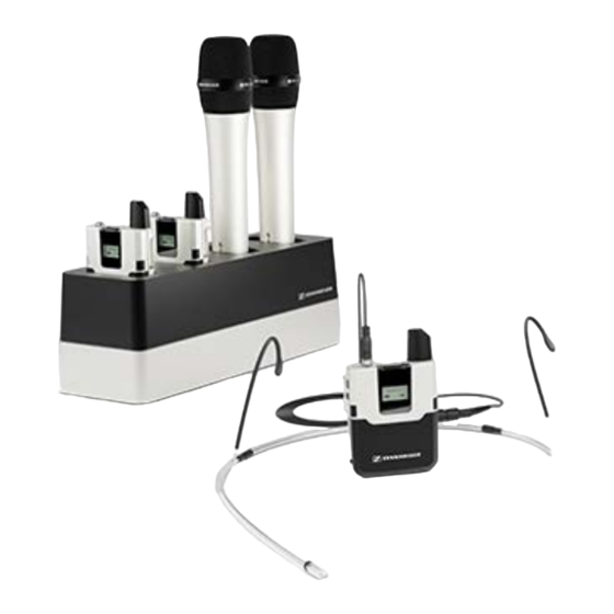
Page 209: The Chg 2 Charger
The CHG 2 charger allows you to simultaneously charge up to two transmitters of the SpeechLine Digital Wireless series. A bi-color LED at each charging slot provides information on the current charge level. The charger has universal charging slots for charging both handheld and bodypack transmitters. - Page 210 | 4 - Instruction manual 4 NT 12-50CS power supply unit • with hollow jack plug for connection to the CHG 2 charger...
-
Page 211: Connecting The Charger To The Power Supply System
| 4 - Instruction manual Connecting the charger to the power supply system To connect the CHG 2 charger to the power supply system: ▷ Connect the cable end of the power supply unit to the socket at the base of the charger. -
Page 212: Charging The Accupack In The Charger
| 4 - Instruction manual Charging the accupack in the charger To charge an accupack in the CHG 2 charger: ▷ Insert the transmitter with the accupack installed and with the charging contacts facing downwards into the charger. ➥ Make sure to insert the transmitter the correct way round: The STANDBY button of the bodypack transmitter has to point in the direction of the charger's charge status LED. -
Page 213: The Chg 2N Charger
SL Bodypack DW and the SL Handheld DW. The four LEDs on each charging slot indicate the current charging status. The versatile network interface is compatible with IPv4 and IPv6 for seamless integration. The Sennheiser Control Cockpit software can be used to monitor and remotely control the settings and status messages. - Page 214 | 4 - Instruction manual 1 Charging slots • Each suitable for both SL Handheld DW and SL Bodypack DW • Charging the accupack in the charger 2 Charge level LEDs • Meaning of the charging slot status LEDs 3 Power supply unit •...
-
Page 215: Connecting The Charger To The Power Supply System
| 4 - Instruction manual Connecting the charger to the power supply system To connect the CHG 2N charger to the power supply system: ▷ Connect the cable end of the power supply unit to the socket at the base of the charger. - Page 216 | 4 - Instruction manual ▷ Guide the cable through the cable guide at the base of the charger so that the charger is stable once in position. ▷ Connect one end of the power cord to the power supply unit and the other end to the wall socket.
-
Page 217: Charging The Accupack In The Charger
| 4 - Instruction manual Charging the accupack in the charger To charge an accupack in the CHG 2N charger: ▷ Insert the transmitter with installed accupack into one of the charger’s two charging slots. Make sure the charging contacts face downward. ▷... -
Page 218: Meaning Of The Charging Slot Status Leds
Accupack charge level < 66 % Accupack charge level < 33 % An error has occurred. A corresponding error message is displayed in the Sennheiser Control Cockpit software. The firmware of the charger is being updated. This LED status is also displayed when new firmware for an SL Handheld DW or SL Bodypack DW transmitter is being loaded to the charger. -
Page 219: Controlling And Monitoring The Charger Over The Network
Cockpit software, refer to the instruction manual of the software. Please note that the host PC on which the Sennheiser Control Cockpit Service is installed must be in the same network as the devices that are to be monitored and controlled. - Page 220 | 4 - Instruction manual Connecting the charger to the network To connect the charger using the Sennheiser Control Cockpit app: ▷ Connect a standard network cable (at least Cat 5) to the Ethernet socket of the charger. ▷ Connect the other end of the network cable to the network, e.g. to a switch or router, or directly to a PC to make initial configuration easier.
- Page 221 If a DHCP server is active in the selected network, the charger receives an IP address automatically. The charger is automatically detected in the Sennheiser Control Cockpit once it is connected to the network, since the CHG 2N is delivered with mDNS activated by default.
- Page 222 If there is no DHCP server in the network and you are working with automatically generated IP addresses, please observe the following information. ▷ Ensure that the host PC on which the Sennheiser Control Cockpit service is installed is configured so that the IP address is assigned automatically, rather than a static configuration.
- Page 223 The charger is delivered with automatic IP assignment configured by default. After adding it in the Sennheiser Control Cockpit, you can reconfigure it to Fixed IP. To do so, proceed as described: Integrating the charger into a network without DHCP using Auto If you wish to do this, you must temporarily reconfigure the host PC on which the Sennheiser...
- Page 224 Add Device function in the Sennheiser Control Cockpit. To add the charger in the Sennheiser Control Cockpit: ▷ Use the Add Device function in the Sennheiser Control Cockpit and enter the pre- configured IP address.
- Page 225 The settings will be reset once you release the reset button. The factory settings are restored: • Automatic IP assignment • mDNS is activated • Name and installation location are reset, provided they were changed in the Sennheiser Control Cockpit.
-
Page 226: Activating Power Saving Mode
| 4 - Instruction manual Activating power saving mode In power saving mode, the transmitters are charged only once. The charger also does not provide any trickle charge. To activate power saving mode: ▷ Hold the network reset button for 10 seconds. ➥... -
Page 227: Updating The Firmware
| 4 - Instruction manual Updating the firmware The firmware of the charger is updated using the Sennheiser Control Cockpit software. You can find more information about this procedure in the software instruction manual or in the download area of the Sennheiser website. -
Page 228: The Chg 4N Charger
SL Bodypack DW and the SL Handheld DW. The four LEDs on each charging slot indicate the current charging status. The versatile network interface is compatible with IPv4 and IPv6 for seamless integration. The Sennheiser Control Cockpit software can be used to monitor and remotely control the settings and status messages. - Page 229 | 4 - Instruction manual 1 Charging slots • Each suitable for both SL Handheld DW and SL Bodypack DW • Charging the accupack in the charger 2 Charge level LEDs • Meaning of the charging slot status LEDs 3 Power supply unit •...
-
Page 230: Connecting The Charger To The Power Supply System
| 4 - Instruction manual Connecting the charger to the power supply system To connect the CHG 4N charger to the power supply system: ▷ Connect the cable end of the power supply unit to the socket at the base of the charger. - Page 231 | 4 - Instruction manual ▷ Guide the cable through the cable guide at the base of the charger so that the charger is stable once in position. ▷ Connect one end of the power cord to the power supply unit and the other end to the wall socket.
-
Page 232: Charging The Accupack In The Charger
| 4 - Instruction manual Charging the accupack in the charger To charge an accupack in the CHG 4N charger: ▷ Insert the transmitter with installed accupack into one of the charger’s four charging slots. Make sure the charging contacts face downward. ▷... -
Page 233: Meaning Of The Charging Slot Status Leds
Accupack charge level < 66 % Accupack charge level < 33 % An error has occurred. A corresponding error message is displayed in the Sennheiser Control Cockpit software. The firmware of the charger is being updated. This LED status is also displayed when new firmware for an SL Handheld DW or SL Bodypack DW transmitter is being loaded to the charger. -
Page 234: Controlling And Monitoring The Charger Over The Network
Cockpit software, refer to the instruction manual of the software. Please note that the host PC on which the Sennheiser Control Cockpit Service is installed must be in the same network as the devices that are to be monitored and controlled. - Page 235 | 4 - Instruction manual Connecting the charger to the network To connect the charger using the Sennheiser Control Cockpit app: ▷ Connect a standard network cable (at least Cat 5) to the Ethernet socket of the charger. ▷ Connect the other end of the network cable to the network, e.g. to a switch or router, or directly to a PC to make initial configuration easier.
- Page 236 If a DHCP server is active in the selected network, the charger receives an IP address automatically. The charger is automatically detected in the Sennheiser Control Cockpit once it is connected to the network, since the CHG 2N is delivered with mDNS activated by default.
- Page 237 If there is no DHCP server in the network and you are working with automatically generated IP addresses, please observe the following information. ▷ Ensure that the host PC on which the Sennheiser Control Cockpit service is installed is configured so that the IP address is assigned automatically, rather than a static configuration.
- Page 238 The charger is delivered with automatic IP assignment configured by default. After adding it in the Sennheiser Control Cockpit, you can reconfigure it to Fixed IP. To do so, proceed as described: Integrating the charger into a network without DHCP using Auto If you wish to do this, you must temporarily reconfigure the host PC on which the Sennheiser...
- Page 239 Add Device function in the Sennheiser Control Cockpit. To add the charger in the Sennheiser Control Cockpit: ▷ Use the Add Device function in the Sennheiser Control Cockpit and enter the pre- configured IP address.
- Page 240 The settings will be reset once you release the reset button. The factory settings are restored: • Automatic IP assignment • mDNS is activated • Name and installation location are reset, provided they were changed in the Sennheiser Control Cockpit.
-
Page 241: Activating Power Saving Mode
| 4 - Instruction manual Activating power saving mode In power saving mode, the transmitters are charged only once. The charger also does not provide any trickle charge. This function is available in firmware version 2.0.3 and later. To activate power saving mode: ▷... -
Page 242: Updating The Firmware
| 4 - Instruction manual Updating the firmware The firmware of the charger is updated using the Sennheiser Control Cockpit software. You can find more information about this procedure in the software instruction manual or in the download area of the Sennheiser website. -
Page 243: The Chg 2W Charging Base
| 4 - Instruction manual The CHG 2W charging base The CHG 2W is a wireless charging base that provides convenient wireless charging. The CHG 2W charging base is compatible with the SL Tablestand 133-S DW, the SL Tablestand 153-S DW and the SL Boundary 114-S DW. Related information Product overview Connecting the charging base to the power supply system... -
Page 244: Connecting The Charging Base To The Power Supply System
| 4 - Instruction manual Connecting the charging base to the power supply system To connect the CHG 2W charger to the power supply system: ▷ Connect the cable end of the power supply unit to the socket at the base of the charger. -
Page 245: Charging A Device Using The Charging Base
| 4 - Instruction manual Charging a device using the charging base You can use the CHG 2W charging base to charge the wireless table stands SL Tablestand 133-S DW and SL Tablestand 153-S DW as well as the wireless boundary microphone SL Boundary 114-S DW. - Page 246 | 4 - Instruction manual The alignment LED on the device tells you whether the device is correctly positioned.
-
Page 247: Meaning Of The Status Leds On The Charging Surfaces
| 4 - Instruction manual Meaning of the status LEDs on the charging surfaces The two blue status LEDs on the charging surfaces provide the following status information: Flashing normally: the device is charging Flashing rapidly: excess temperature warning Flashing/flickering very rapidly: unknown device on the charger... -
Page 248: Awm 2 / Awm 4 Remote Antennas
| 4 - Instruction manual AWM 2 / AWM 4 remote antennas The AWM 2 and AWM 4 antennas for wall mounting can be mounted away from the receivers so that they are in the optimum position and virtually invisible. This is useful, for example, when the receivers need to be installed in such a way that they cannot be seen or when the receiver position is not the optimum position for the antenna. -
Page 249: Product Overview
| 4 - Instruction manual Product overview 1 Antennas 2 Connections for Link I 3 Connections for Link II (AWM 4 only... -
Page 250: Attaching The Antennas
| 4 - Instruction manual Attaching the antennas ▷ Screw the supplied rod antennas onto the housing as shown. -
Page 251: Connecting The Antenna Cables
| 4 - Instruction manual Connecting the antenna cables You can connect one receiver directly to the AWM 2 and two receivers directly to the AWM 4. ▷ Connect the two antenna outputs ANT I and ANT II of the first receiver to the connections LINK I of the AWM 2 or AWM 4. - Page 252 | 4 - Instruction manual For direct connection of the receivers to the AWM 2 or AWM 4, we recommend using the following low-loss Sennheiser antenna cables: • CL 1 PP • CL 5 PP • CL 10 PP •...
-
Page 253: Mounting The Antenna On A Stand Or On The Wall
| 4 - Instruction manual Mounting the antenna on a stand or on the wall ▷ You can either screw the AWM 2 and AWM 4 onto a standard microphone stand or use the existing holes in the housing to mount it on the wall as shown. -
Page 254: The Sl Pasc 2 Passive Antenna Splitter/Combiner
SpeechLine Digital Wireless microphone series. It is used to distribute the antenna signals from up to 2 SpeechLine Digital Wireless radio links. In combination with the AWM 2 or AWM 4 remote antennas, the number of required antenna cables is reduced to a minimum. The rack receivers are connected to the SL PASC 2 using the supplied SMA-R cables. -
Page 255: The Sl Pasc 4 Passive Antenna Splitter/Combiner
SpeechLine Digital Wireless microphone series. It is used to distribute the antenna signals from up to 4 SpeechLine Digital Wireless radio links. In combination with the AWM 2 or AWM 4 remote antennas, the number of required antenna cables is reduced to a minimum. The rack receivers are connected to the SL PASC 4 using the supplied SMA-R cables. -
Page 256: Installing Antenna Splitters In A Rack
| 4 - Instruction manual Installing antenna splitters in a rack This chapter describes how to install a single antenna splitter or two antenna splitters side by side in a rack. To install the antenna splitter in a rack, you need the GA 4 mounting kit, see GA 4 mounting kit. - Page 257 | 4 - Instruction manual To install the antenna splitter in a rack: ▷ Screw the front panel from the GA 4 mounting kit onto the antenna splitter’s mounting angle using the two included recessed head screws as shown in the figure. ➥...
- Page 258 | 4 - Instruction manual To mount the jointing plate: ▷ Place the two antenna splitters side by side on a flat surface with the undersides facing upward. ▷ Screw the two antenna splitters together using the jointing plate and the six recessed head screws, as shown in the figure.
-
Page 259: Contact
5. Contact Contact information in case of questions about our products and/or services. Questions about the product / Help with technical issues If you have any questions about our products and/or services, please do not hesitate to contact us at https://www.sennheiser.com/support. - Page 260 Sennheiser electronic SE & Co. KG | Am Labor 1 | 30900 Wedemark | Germany...
Need help?
Do you have a question about the SpeechLine Digital Wireless and is the answer not in the manual?
Questions and answers