Table of Contents
Advertisement
Quick Links
Air-conditioner Control System
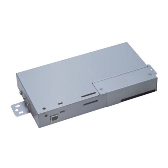
Centralized Controller
Model: GB-24A
Before installing the controller, please read this Installation Manual carefully to ensure proper operation.
Retain this manual for future reference.
1. Safety Precautions..................................................... 1
2. Parts List.................................................................... 3
3. Product Features ....................................................... 4
4. System Diagram ........................................................ 5
5. Installation.................................................................. 8
1. Field-supplied parts............................................... 8
3. Installation ............................................................. 9
6. Wiring....................................................................... 12
1. Ground cable. ..................................................... 12
2. Cover removal and installation............................ 12
3. M-NET transmission line ..................................... 13
4. LAN connection................................................... 13
7. Initial Setting ........................................................... 14
1. Setting the IP address with dip switches............. 15
2. Setting the service switch.................................... 15
8. Test Run .................................................................. 16
1. Collective operation, ON/OFF ............................. 16
2. Service LED display ............................................ 16
9. System Wiring Example........................................... 17
10. External Input/Output Usage .................................. 19
1. External signal input function .............................. 19
2. External signal output function ............................ 21
Installation Manual
Contents
Advertisement
Table of Contents

Related Manuals for Mitsubishi Electric GB-24A


Summary of Contents for Mitsubishi Electric GB-24A
-
Page 1: Table Of Contents
Air-conditioner Control System Centralized Controller Installation Manual Model: GB-24A Contents 1. Safety Precautions............. 1 2. Parts List..............3 3. Product Features ............4 4. System Diagram ............5 5. Installation..............8 1. Field-supplied parts..........8 2. Maximum length of M-NET transmission lines..8 3. -
Page 2: Safety Precautions
This manual describes how to install the centralized controller and wiring. Before installing the controller, read the Safety Precautions section carefully to ensure proper installation. Safety Precautions Safety symbols used in this manual The following symbols are used in this manual to indicate the type and severity of potential consequences that may result when given instructions are not followed exactly as stated. - Page 3 It may cause a fire or malfunction. Use a security device such as a VPN router when To reduce the risk of electric shock, install and connecting the GB-24A to the Internet to prevent wire the unit with the power to power supply unit unauthorized access.
-
Page 4: Parts List
Unit that supplies the The number of Remarks power to GB-24A connectable GB-24A When only one GB-24A unit is connected Up to two PAC-SC51KUA 1 unit *1 other system controllers can be connected to the transmission line for central control. -
Page 5: Product Features
Product Features 1. Specification Item Contents Interface M-NET: 30V/24V DC; 0.13/0.15A External I/O: 12V DC or 24V DC (External power supply) Ethernet: 10Base-T Environmental Temperature Operating range: 32 to 104ºF / 0 to 40ºC conditions Storage range: - 4 to +140ºF / -20 to +60ºC Humidity 30-90%RH (No condensation) Dimensions... -
Page 6: System Diagram
System Diagram 1. System with a power supply unit Indoor unit Power supply unit (optional) Centralized controller Local remote controller Model: PAC-SC51KUA, PAC-SC50KUA Model: GB-24A To PC M-NET transmission line MA remote controller line M-NET M-NET The numbers in the outdoor unit indicate the address No. - Page 7 NOTE * If the outdoor unit Group 4 Group 5 malfunctions or is turned off, the GB-24A that is connected to the outdoor unit will also shut down. * This diagram does not show the AC power supply wiring. Only the configuration for the transmission line is shown.
- Page 8 NOTE * This system controller is designed as a main controller, not as a sub controller. Main system controller (main SC) The main system controller is designed to control all units, including units that other system controllers control. When there is only one system controller in a system, it will become the main system controller. Group setting or interlock setting can be made only with the main system controller.
-
Page 9: Installation
* 1: Specifications do not include the remote control cables up to 32 ft (10m) in length. If the remote control cable exceeds 32 ft (10m), the excess must be added to the total length in order to avoid exceeding the maximum length. Example ℓ3 ℓ1 ℓ2 GB-24A Outdoor unit Indoor Indoor Indoor Power ℓ4... -
Page 10: Installation
Installation methods for the centralized controller GB-24A are shown below. Method1: Horizontal installation using L-fittings Attach two L-fittings to GB-24A using the supplied screws (Fig. 5-1), then install GB-24A (Fig. 5-2). Install the GB-24A in a metal control panel box (steel: thickness 3/64 in (1mm) or more). - Page 11 Method2: Vertical installation using L-fittings After removing the screws on GB-24A, attach two L-fittings to the unit using the supplied screws (Fig. 5-3), then install (Fig. 5-4). Install the GB-24A in a metal control panel box (steel : thickness 3/64 in (1mm) or more).
- Page 12 To secure, screw pitch of 7.88inch (200mm) or less is required when DIN rail is attached on the metal control board. Use GB-24A in a place where it is not subjected no vibrations. Use studs as necessary to attach GB-24A.
-
Page 13: Wiring
Wiring WARNING All electric work must follow local regulations. Improper electrical work may result in electric shock or fire. Shut off the power source of the unit and all other units to be connected to the power supply unit before wiring. CAUTION Do not connect the AC power line to the M-NET terminal blocks of this device, otherwise the unit may fall. -
Page 14: M-Net Transmission Line
If the cables aren’t securely attached, it may cause heat generation, a fire, etc. LAN connection Connect the LAN cable to the LAN connector of the GB-24A unit. Field-supply the LAN cable, and use an enhanced category 5 UTP cable. 5 Instalación... -
Page 15: Initial Setting
The functions that can be initialized using this unit are described in this manual. Refer to the initial setting web operation manuals for more information. The format in which the Web page address for each GB-24A is expressed on the Initial Setting Web, as well as the default setting user name and password are shown below. -
Page 16: Setting The Ip Address With Dip Switches
When setting IP addresses with the Initial Setting Web, set all four dip switches on SW2 to OFF. If the IP address of GB-24A is forgotten, check the IP address that is registered on the monitoring PC (Web). GB-24A can be started by changing the setting of SW2 on GB-24A IP address, and using a temporary arbitrary fixed IP address. -
Page 17: Test Run
An operation mode other than “Test run” can be selected on the Web browser. The format in which the Web page address for each GB-24A is expressed on the Web browser, as well as the default setting user name and password are shown below. For further details, refer to the manual for the Web browser. -
Page 18: System Wiring Example
System Wiring Example Power supply * GB-24A requires 24-32V DC power supply (M-NET) for centralized control transmission use, operation, and LAN function use. (1) Power supply of 24-32V DC from power supply unit PAC-SC50(51)KUA. Power supply unit PAC-SC50(51)KUA is recommended for GB-24A. See the diagram below;... - Page 19 (2) Power supply of 30V DC from outdoor unit connector TB7. As shown on Fig. 9-2, GB-24A receives power supply of 30V DC from R410A CITY MULTI outdoor unit connector TB7. If one of the outdoor units should change its power supply switch CN41 to CN40.
-
Page 20: External Input/Output Usage
External Input/Output Usage 1. External signal input function * External signal input requires the external I/O adapter (Model: PAC-YG10HA), sold separately. Some parts, such as 12V DC or 24V DC power supply and relays, must be field-supplied. (1) External input Emergency stop/normal, run/stop and prohibit/enable of local remote controller operation can be controlled for all air conditioners on a system by using a voltage (12V DC or 24V DC) contact signal from an external source. - Page 21 (3) External input specification Emergency stop/normal ON/OFF, Lead wire ON/OFF, prohibit/enable pulse signal level signal level signal No. 5 Orange Emergency stop/normal ON/OFF input ON input input No. 6 Yellow Not used Not used OFF input No. 7 Blue Not used Not used Local remote controller operation prohibit input No.
-
Page 22: External Signal Output Function
2. External signal output function * External signal output requires the external I/O adapter (Model: PAC-YG10HA) sold separately. Some parts, such as 12V DC or 24V DC power supply and relays, must be field-supplied. (1) External output When one or more air conditioners are operating, the “ON” signal will be output, and if a malfunction occurs in one or more air conditioners, the “Malfunction”... - Page 23 NOTE: This equipment has been tested and found to comply with the limits for a Class B digital device, pursuant to Part 15 of the FCC Rules. These limits are designed to provide resonable protection against harmful interference in a residential installation.
- Page 24 Please be sure to put the contact address/telephone number on this manual before handing it to the customer. WT05501X04 Printed in Japan Recycled Paper...
Need help?
Do you have a question about the GB-24A and is the answer not in the manual?
Questions and answers