Table of Contents
Advertisement
Quick Links
VEHICLE SENSOR
VEHICLE SENSOR
When a VEHICLE SENSOR is in use, the automatic gate opener could be activated by
When a VEHICLE SENSOR is in use, the automatic gate opener could be activated by
a child on a bicycle, tricycle or other metal play equipment. This product is not recom-
a child on a bicycle, tricycle or other metal play equipment. This product is not recom-
mended or applications exposed to children.
mended or applications exposed to children.
Parts Identifcation:
Parts Identifcation:
Double Spade
Double Spade
Connectors (2)
Connectors (2)
Battery Connection
Battery Connection
Wires (2)
Wires (2)
GTO, Inc. • 3121 Hartseld Road • Tallahassee, Florida 32303
GTO, Inc. • 3121 Hartseld Road • Tallahassee, Florida 32303
1-800-543-GATE (4283) • Technical Support 1-800-543-1236
1-800-543-GATE (4283) • Technical Support 1-800-543-1236
Installation Manual
Installation Manual
WARNING
WARNING
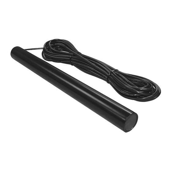
SENSOR with 50 feet
SENSOR with 50 feet
of Direct Burial Cable
of Direct Burial Cable
!
!
W A
W
A R
R N
N I I N
N G
G
Ty-Wraps
Ty-
Wraps (4)
www.mightymule.com
www.mightymule.com
®
®
WARNING
WARNING
!
!
WARNING
WARN
GATE OPENING SENSOR IN USE
GATE OPENING
SENSOR IN USE
The Automatic Gate Opener is activated when a
The Automatic Gate Opener is activated when a
vehicle comes within range of the sensor buried
vehicle comes within range of the sensor buried
along side the driveway and could possibly be
along side the driveway and could possibly be
activated by a child on a bicycle, tricycle or other
activated by a child on a
bicycle, tricycle or other
metal play equipmen
metal play equipment. t.
Warning Signs (2)
Warning Signs (2)
(4)
Wire Nuts (3)
Wire Nuts (3)
ING
Wire Clamp
Wire Clamp
Range
Range
Adjustment Board d
Adjustment Boar
RWINSTMM
RWINSTMM
rev-5/18/07
rev-5/18/07
Advertisement
Table of Contents

Related Manuals for Mighty Mule VEHICLE SENSOR


Summary of Contents for Mighty Mule VEHICLE SENSOR
- Page 1 WARNING WARNING When a VEHICLE SENSOR is in use, the automatic gate opener could be activated by When a VEHICLE SENSOR is in use, the automatic gate opener could be activated by a child on a bicycle, tricycle or other metal play equipment. This product is not recom- a child on a bicycle, tricycle or other metal play equipment.
- Page 2 For this reason we do not recommend the For this reason we do not recommend the VEHICLE SENSOR in enviro VEHICLE SENSOR in environments exposed to nments exposed to children.
- Page 3 Conversion Chart Conversion Chart Converting Metric Units to English Equivalents Converting Metric Units to English Equivalents When When Y Y ou ou Know Know Multiply Multiply By T T o o Find Find Symbo Symbol l centimeters centimeters 0.3937 0.3937 inches inches in.
- Page 4 MAGNETIC FIELD, GNETIC FIELD, thus acti thus activating vating the gate the gate opener opener. . How the VEHICLE SENSOR’s RANGE ADJUSTMENT works How the VEHICLE SENSOR’s RANGE ADJUSTMENT works • • The RAN The RANGE dis GE distance can tance can be adj be adjusted ro...
- Page 5 • • The SENSOR SENSOR comes comes with with 50 50 eet eet o o cable. cable. A A typi- typi- cal installation will require about 5 eet o cal installation will require about 5 eet o cable cable Driveway Driveway to come rom the ground up to come rom the ground up and into the control...
-
Page 6: Installing The Wire Clamp
to prevent magnetic disturbance during testing and installation. Step 1: Step 1: Determine the optimum location or the VEHICLE SENSOR Determine the optimum location or the VEHICLE SENSOR using the inormation ound in using the inormation ound in “Placement “Placement o... - Page 7 Wiring the SENSOR to Mighty Mule Gate Openers: Wiring the SENSOR to Mighty Mule Gate Openers: IMPORTANT: IMPORTANT: power and dis- power and dis- TURN OFF the TURN OFF the connect the battery wires b connect the battery wires b eore you begin to connect...
-
Page 8: Connecting The Range Adjustment Control Board
Mighty Mule FM500 & FM502 Control Box Mighty Mule FM500 & FM502 Control Box Mighty Mule FM700 & FM702 Control Box Mighty Mule FM700 & FM702 Control Box... -
Page 9: Adjusting The Range
Powering Up the SENSOR: Powering Up the SENSOR: Double Spade Connectors Double Spade Connectors included with SENSOR included with SENSOR IMPORTANT: When the SENSOR IMPORTANT: When the SENSOR RED Opener Battery Wire RED Opener Battery Wire is frst powered up it must be un- is frst powered up it must be un- disturbed or 60 seconds to disturbed or 60 seconds to perorm... - Page 10 VEHICLE SENSOR VEHICLE SENSOR tion below or wiring the system. I you do not understand the instructions below, please call GTO’s tion below or wiring the system.
-
Page 11: Troubleshooting
TECHNICAL SPECIFICATIONS: TECHNICAL SPECIFICATIONS: • • Power supply: 8-26 Vac/dc. Power supply: 8-26 Vac/dc. • • Current consumption: 1.5 mA typical. Current consumption: 1.5 mA typical. • • Relay rating: Latching Relay rating: Latching relay relay. . Nominal Nominal switching switching capacit capacity y (resistive (resistive load) - Page 12 orced entry or exit. it. Solenoid dri Solenoid driven, ven, plated steel bolt lock with a zinc plated steel bolt lock with a zinc plated steel housing. Used with Mighty Mule plated steel housing. Used with Mighty Mule I I C C ...
Need help?
Do you have a question about the VEHICLE SENSOR and is the answer not in the manual?
Questions and answers