Table of Contents
Advertisement
INSTALLATION AND OPERATING INSTRUCTIONS
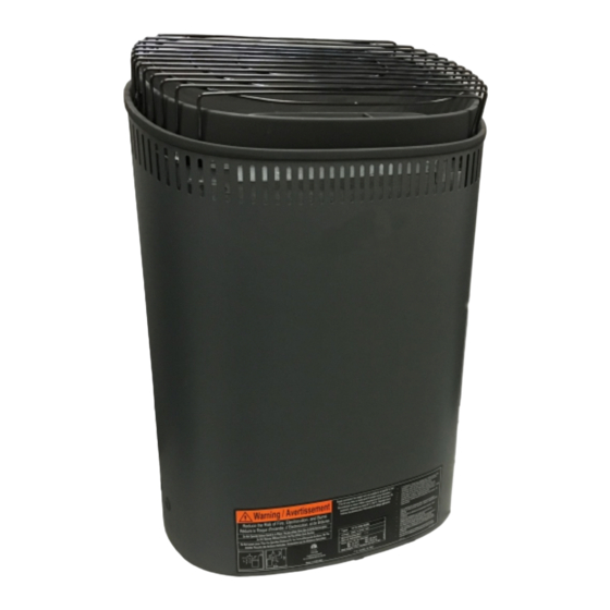
Vena/Fonda Pure 2.0/Trend/A3 Series Heater
with BWT
Models 4.5, 6.0, 8.0
(Model #'s 1712-450-1706, 1712-600-1706, 1712-800-1706)
w
ith
Pure 2.0 Control
Read all instructions carefully before installation. Please leave all
instructions and warranty with the owner.
WARNING
Prolonged exposure to elevated temperatures is capable of inducing
hyperthermia. Hyperthermia occurs when the internal temperature of the
body reaches several degrees above the normal body temperature of
98.6°F. The symptoms of hyperthermia include an increase in the normal
temperature of the body, dizziness, lethargy, drowsiness, and fainting. The
effects of the hyperthermia include failure to perceive heat, failure to
recognize the need to exit the room, unawareness of impending hazard,
fetal damage in pregnant women, physical inability to exit the room and
unconsciousness.
WARNING
The use of alcohol, drugs, or medication is capable of greatly increasing
the risk of fatal hyperthermia.
SECTION 1: GENERAL INFORMATION
These heaters are ETL approved by Intertek for permanent installations and
electrical connections. Built with splash proof construction, the conducting
parts are protected against water. All wiring must be performed in
accordance with national and local codes. See Diagram 2 for wire and
room size requirements. These heaters are wall mounted.
72-0105 01-24-2020
(Model 1601-40 and 1601-40-1)
WARNING
Do not take a sauna if using
alcohol, drugs or
medications.
Pregnant women or persons
with poor health should
consult their physician before
using any sauna.
Caution re hazard: Do not
use the sauna room for
drying clothes, bathing suits,
etc. Do not hang towels
above heater or place any
object other than the rocks
supplied on the heater. If any
darkening of the wall around
the heater is noticed
discontinue sauna use
immediately.
.
Inspect sauna regularly for
required maintenance to
heater, control and benches.
Replace wood surfaces
which show any signs of
deterioration.
The heater gets extremely hot
during operation and should
not be touched or burns may
Minors should be adequately
supervised whenever near a
hot or warming sauna.
7013546 314 SKSM 219 C
Page 1
result.
Advertisement
Table of Contents

Related Manuals for TyloHelo A3 Series


Summary of Contents for TyloHelo A3 Series
-
Page 1: Section 1: General Information
Do not hang towels above heater or place any Vena/Fonda Pure 2.0/Trend/A3 Series Heater object other than the rocks supplied on the heater. If any with BWT darkening of the wall around Models 4.5, 6.0, 8.0... - Page 2 INSTALLATION AND OPERATING INSTRUCTIONS Page 2 DIAGRAM 1 MOUNTING BRACKET LOCATION AND MINIMUM DISTANCE TO COMBUSTIBLE MATERIAL 4” 13½” Temperature Sensor (Upper Bench) 2" " 6" -5/8 Guard Rail Screws 21" 3" Use the long screws in the upper High Limit Control holes of the mounting bracket Recheck your distances from the heater to combustible materials to be sure you have...
-
Page 3: Section 2: Mounting Of Sauna Heater
INSTALLATION AND OPERATING INSTRUCTIONS Page 3 WARNING SECTION 2: MOUNTING OF SAUNA HEATER HANGING THE HEATER Using the template provided, drill four 9/64" holes Fire sprinkler systems used to fasten the heater to the wall. Install two ¼" x 1 ½" hex head lag screws inside any sauna room should (supplied with the heater) into the upper two holes. - Page 4 INSTALLATION AND OPERATING INSTRUCTIONS Page 4 DIAGRAM 3 Sensor protective cover. Locate bottom of sensor 5" from ceiling All wiring for sauna system or accessories and directly above of heater. should be routed inside the walls or away from the high temperature air from the sauna heater. Sensor Wire Controls CAN NOT be installed above the sauna...
- Page 5 INSTALLATION AND OPERATING INSTRUCTIONS Page 5 DIAGRAM 6 Heater Models 1712-45-1706 4.5 kW 1712-60-1706 6.0 kW 1712-80-1706 8.0 kW Pure 2.0 Sensor Control 1712-450-1706 4.5 kW 1712-600-1706 6.0 kW 1601-40 or 1601-40-1 1712-800-1706 8.0 kW Front Element Middle Element Back Sensor Element X4 X6 X8...
- Page 6 INSTALLATION AND OPERATING INSTRUCTIONS Page 6 DIAGRAM 6 Continued Heater Models 1712-45-1706 4.5 kW 1712-60-1706 6.0 kW 1712-80-1706 8.0 kW Pure 2.0 Sensor Control 1712-450-1706 4.5 kW 1712-600-1706 6.0 kW 1601-40 or 1601-40-1 1712-800-1706 8.0 kW Front Element Middle Element Back Sensor Element...
-
Page 7: Section 7: Control Installation & Operation
INSTALLATION AND OPERATING INSTRUCTIONS Page 7 WARNING SECTION 7: CONTROL INSTALLATION & OPERATION INSTALLATION ROUGH IN: Place the control inside or outside the sauna room. If Do not locate benches over the control is installed inside a sauna room, the top of the unit cannot be higher heater. -
Page 8: Section 8: High Limit Control (Reset Button)
INSTALLATION AND OPERATING INSTRUCTIONS Page 8 SECTION 7: OPERATION, Continued FAHRENHEIT or CELSIUS: The temperature will be displayed in Fahrenheit as default. To change the temperature display, apply power to the system for over 5 minutes and the LED temperature indicator must be glowing. Next, press the < button for 5 seconds. After 2 seconds the temperature indicator will start ashing, and a C or F will appear in the temperature display to indicate that the temperature display has been changed. - Page 9 INSTALLATION AND OPERATING INSTRUCTIONS Page 9 DIAGRAM 7 DIAGRAM 8 TYPICAL PRE-CUT WALL CONSTRUCTION HEATER SCREEN (GUARD RAIL) Minimum Dimensions 1/2" wallboard 2x4" framing berglass insulation foil vapor barrier T&G soft wood 1/2" wallboard DIAGRAM 9 DIAGRAM 10 a. Loosely place rocks between Incorrect Placement VENTILATION the elements so air ow is not...
-
Page 10: Section 10: Warning Placards
INSTALLATION AND OPERATING INSTRUCTIONS Page 10 SECTION 10: WARNING PLACARDS WARNING Two metal placards are included in the Installation Instruction Envelope The "CAUTION" and packaged with every Sauna Heater. The CAUTION placard must be attached "WARNING" placards must be to the interior wall of the sauna room directly above the heater where it is mounted in accordance with visible to the bather. -
Page 11: Section 13: Maintenance
INSTALLATION AND OPERATING INSTRUCTIONS Page 11 SECTION 13: MAINTENANCE Inspect sauna room at the end of each day the room to ensure the control and system is off. The sauna, like a bathroom, should be kept clean and odor free. Towels or mats should always be used on benches and oor as perspiration otherwise penetrates the soft wood. - Page 12 INSTALLATION AND OPERATING INSTRUCTIONS Page 12 DIAGRAM 12: ROOM TEMPERATURES 190° F Ceiling Non-Typical Ceiling Height 140° F Head Height Notes: Temperatures vary in a sauna room by height and distance from heater. Ventilation will help reduce it but will not 125°...
-
Page 13: Section 15: Troubleshooting
INSTALLATION AND OPERATING INSTRUCTIONS Page 13 SECTION 15: TROUBLESHOOTING Control will Run but No Heat - Press the (reset) high limit switch on the bottom of heater. No Heat - Ensure control in not in delay mode (Hour Glass LED glowing) Slow Heat Time or High Limit Tripping - Check rock placement, they will break down over time and reduce the air ow in the heater.
Need help?
Do you have a question about the A3 Series and is the answer not in the manual?
Questions and answers