
Related Manuals for Dynascan 10M


Summary of Contents for Dynascan 10M
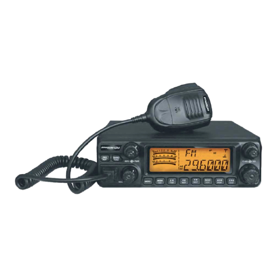
- Page 1 TRANSCEPTOR MOVIL DE 10 METROS PARA RADIOAFICIONADOS MANUAL DE INSTRUCCIONES Español...
- Page 2 INDICE Página SIMBOLOS Y DEFINICIONES FUNCIONES Y CARACTERISTICAS ARTICULOS SUMINISTRADOS INSTALACION FAMILIARIZARSE CON EL TRANSCEPTOR FUNCIONAMIENTO DEL TRANSCEPTOR FUNCIONES DEL TECLADO MENU DE FUNCIONES ESPECIFICACIONES TECNICAS 9.1.- GENERALES 9.2.- TRANSMISOR 9.3.- RECEPTOR 10.- SOLUCION DE PROBLEMAS 11.- DECLARACION DE CONFORMIDAD 12.- GARANTIA Español - 2 -...
- Page 3 1.- SIMBOLOS Y DEFINICIONES: Para el uso de este equipo en España es necesaria autorización administrativa o licencia concedida por las autoridades de Telecomunicación. Pueden existir restricciones para su uso en cualquier Estado Miembro de la Unión Europea, para más información consulte con su vendedor o Autoridades de Telecomunicación.
- Page 4 2.- FUNCIONES Y CARACTERISTICAS: - Gran pantalla LCD con visualización de la frecuencia y todo tipo de información. - Modos FM, AM, USB, LSB, PA. - Saltos de frecuencia de 100 Hz, 1 kHz, 10 kHz, 100 kHz, 1 MHz. - Ajuste del “Clarifier”...
- Page 5 3.- ARTICULOS SUMINISTRADOS: Transceptor móvil Micrófono Soporte de montaje Soporte para el DYNASCAN 10M micrófono Juntas antideslizantes Cable de Tornillos para el Arandelas para el soporte de montaje alimentación soporte de montaje Mariposas para el montaje Fusible de repuesto Tornillos...
- Page 6 CONEXION DEL MICROFONO: 1.- Inserte el conector del micrófono en el conector del transceptor. 2.- Para retirar el micrófono, presione la lengüeta de retención del conector y tire de él cuidadosamente para retirarlo. INSTALACION DE LA ANTENA: Antes de utilizar este transceptor, instale una antena de alta eficiencia ajustada a la banda de 10 metros, una antena adecuada y una correcta instalación le proporcionará...
- Page 7 CONEXION DE LA ALIMENTACION: Este transceptor se alimenta con 13,8 Vcc, no conectarlo jamás a una alimentación de 24 Vcc. La batería del vehículo deberá suministrar 13,8 Vcc y la corriente suficiente para el funcionamiento del transceptor, en caso contrario la pantalla LCD del transceptor se oscurecerá y la potencia de transmisión disminuirá.
-
Page 8: Panel Frontal
INSTALAR EL SOPORTE DEL MICROFONO: Elija una ubicación en la que el micrófono no moleste al conductor ni a los pasajeros del vehículo. Utilice los tornillos autorroscantes y las arandelas suministrados (2 juegos) para fijar el soporte del micrófono. CONEXION DE UN ALTAVOZ EXTERIOR: Si utiliza un altavoz externo, elija un altavoz de 8 Ω... -
Page 9: Panel Trasero
Nº Tecla Funciones Permite seleccionar entre el modo canal y el modo frecuencia, y ajustar el “Offset”. BAND Permite seleccionar la banda: A-I y ajustar el ECO. MENU Tecla para acceder al menú de ajustes. MODE Permite seleccionar FM, AM USB, LSB, PA y el ajuste “TSQ”. Escaneado en doble escucha, función +10 kHz. -
Page 10: Pantalla Lcd
MICROFONO: PANTALLA LCD: Nº Icono Descripción Indicador del nivel de la señal RX. Indicador del nivel relativo de la señal TX. Indicador SWR. Modelo del transceptor. Español - 10 -... -
Page 11: Funcionamiento Del Transceptor
Función de bloqueo del teclado activada. Aparece cuando se pulsa la tecla [MENU]. FUNC Aparece cuando se selecciona el canal de emergencia. Aparece cuando se ajusta el mando clarifier para SSB. Aparece cuando se utiliza la función “AQ”. Aparece cuando el escaneado está activado. Muestra el tipo de modulación. - Page 12 AJUSTE DE LA GANANCIA DE RF: Cuando el transceptor está recibiendo, gire el eje interior del mando [RFG] para ajustar la ganancia de RF. Gire este mando en sentido de las agujas del reloj para aumentar la ganancia, gírelo en sentido contrario a las agujas del reloj para reducir la ganancia.
- Page 13 REP-: Función de dirección de desplazamiento de frecuencia activada. La frecuencia de recepción será mayor que la frecuencia de transmisión. 3.- Pulse el mando [CH] para almacenar el ajuste y salir. ● Tecla [BAND/TONE]: Selección de banda: Pulse brevemente la tecla [BAND] para seleccionar la banda A-B-C-D-E-F-G-H-I. Función “ECO”: 1.- Mantenga pulsada la tecla [BAND] durante 2 segundos para activar la función “ECO”, en la pantalla se visualizará...
- Page 14 ● Tecla [RB/BEEP]: Función “RB”: 1.- Pulse brevemente la tecla [RB] para activar la función “RB”, en la pantalla se visualizará “RB”. 2.- Pulse el mando [CH] para seleccionar la frecuencia para la función “RB”, gire el mando [CH] para seleccionar: OFF ~ 5, dispone de un total de 6 grupos.
- Page 15 Almacenar/Eliminar un canal de memoria: 1.- Almacenar un canal en memoria: Cuando el transceptor no está en modo memoria, seleccione el canal que desea almacenar, y mantenga pulsada la tecla [MEM] para acceder al modo de almacenamiento, el número de canal parpadeará.
-
Page 16: Especificaciones Tecnicas
SQ: Escaneado por squelch. Tipo de escaneado TI: Escaneado por tiempo. La programación por defecto es “SQ”. OFF: Función desactivada. R: Ajuste de la frecuencia de recepción. Mando Ajuste frecuencia clarificador para transmisión. RT: Ajuste de la frecuencia de recepción y transmisión. -
Page 17: Solucion De Problemas
Distorsión de intermodulación: En SSB: 3er orden >-25dB; en 5º orden >-35 dB. Supresión de portadora en SSB: 55 dB. Rechazo de banda lateral: 50 dB. Emisión de espúreas: <50 dB. 9.3.- RECEPTOR: Sensibilidad: 0.25 µV en SSB para 10 dB (S+N)/N. 1 µV en AM para 10 dB (S+N)/N. -
Page 18: Declaracion De Conformidad
11.- DECLARACION DE CONFORMIDAD: Español - 18 -... -
Page 19: Certificado De Garantia
12.- GARANTIA: CERTIFICADO DE GARANTIA Marca del aparato: Modelo: Nº serie: Fecha de compra: Sello del establecimiento vendedor: ADVERTENCIA: La garantía es válida siempre y cuando esté total y debidamente cumplimentada de forma legible y clara, presente el sello del establecimiento vendedor y tenga adjuntado el ticket o factura de compra del aparato. - Page 20 10 METER RADIOAMATEUR MOBILE TRANSCEIVER USER´S MANUAL English...
- Page 21 INDEX Page no. DEFINITIONS FUNCTIONS & FEATURES SUPPLIES ARTICLES INSTALLATION GETTING ACQUAINTED TRANSCEIVER OPERATION KEYPAD OPERATION FUNCTIONS MENU TECHNICAL SPECIFICATIONS 9.1.- GENERAL 9.2.- TRANSMITTER 9.3.- RECEIVER 10.- TROUBLESHOOTING 11.- DECLARACION OF CONFORMITY 12.- GUARANTEE English - 2 -...
- Page 22 1.- DEFINITIONS: Restrictions can exist for the use this equipment in any European Union member states, for more information it consults with their salesperson or Telecommunication Authorities. Member states of the European Union where this equipment may be used: This equipment complied whit Directive 2012/19/EU on waste electrical and electronic equipment (WEEE).
-
Page 23: Functions And Features
2.- FUNCTIONS & FEATURES: - Big LCD displays frequency and all kinds of information. - FM, AM, SSB, LSB, PA mode. - Frequency tuning step 100 Hz, 1 kHz, 10 kHz, 100 kHz, 1 MHz. - ±1.5 kHz clarifier adjustment. - Menu function setup. -
Page 24: Supplied Articles
3.- SUPPLIED ARTICLES: Mobile transceiver Microphone Mounting bracket Microphone DYNASCAN 10M Hanger Non-slip mat Power cable Screws for bracket Pads for bracket Adjusting screws Spare fuses Self-tapping screws Pads (15 A, 250 V) 4.- INSTALLATION: Choose the most appropriate setting from a simple and practical point of view. Your transceiver should not interfere with the passengers, or vehicle driver or crash the driver's knee or leg when rush brake. -
Page 25: Microphone Connection
MICROPHONE CONNECTION: 1.- Plug microphone connector into jack. 2.- To remove the microphone, pull on the screw for microphone connector. ANTENNA INSTALLATION: Before using this transceiver, install a high efficient and harmonious adjusted 10 meters antenna, suitable antenna type and correct installation will bring excellent communication. To match with the transceiver, the antenna and cable shall with characteristic impedance of 50 Ω, otherwise the antenna system will not efficient enough and will disturb TV, radio or other electronics equipment’s. -
Page 26: Replacing Fuse
Notes: - We suggest not use cigar lighter as it often bring down the voltage. - Locate the power cable away from high temperature, moisture and fire. - Use the transceiver power cable without remove the fuse holder from the cable. 1.- Connect red power cable with the positive terminal (+) of the battery. - Page 27 INSTALL MICROPHONE HANGER: Choose an ideal location which will not interfering the driver or passengers of the vehicle. Using supplied self-tapping screws and pads (2 sets) to fix the hanger. INSTALL EXTERNAL SPEAKER: If use an external speaker, choose 8 Ω speaker with 3.5 mm mono band plug. 1.- Locate the external speaker in a suitable place.
-
Page 28: Rear Panel
RF power control. RF gain control. Squelch control. CLAR “SSB” clarifier switch. Power On/Off, volume control. Channel switch, push key. Microphone jack. LCD display. REAR PANEL: Function External speaker jack. External PA jack. Antenna connector. Power supply connector. English - 9 -... -
Page 29: Lcd Display
MICROPHONE: LCD DISPLAY: Icon Description RX signal strength indicator. TX signal strength indicator. SWR strength indicator. Model name indicator. Keypad lock function activated. Appears when press [MENU] key. FUNC English - 10 -... - Page 30 Appears when using emergency channel. Appears when adjust SSB clarifier frequency. Appears when use “AQ” function. Appears when scan function is ON. Display the modulation type. Appears when the “CTCSS” signaling is enabled. Appears when the “DCS” signaling is enabled. Appears when “Hi-cut”...
- Page 31 SQUELCH CONTROL: When the transceiver is in standby mode, turn the [SQ] outer shaft knob clockwise to adjust squelch level. The LCD displays “SQ: XX”. (“XX” stands for the squelch level, total 1-36 levels). SSB CLARIFIER CONTROL: When the transceiver is in transmitting or receiving mode, turn the [CLAR] inner shaft knob to adjust “USB/LSB”...
- Page 32 ● [MENU] key: Press and hold the [MENU] key for 2 seconds to enter menu list. ● [MODE/TSQ] key: Modulation: Short press the [MODE] key to choose mode FM-AM-USB-LSB-PA. “CTCSS/DCS” function: 1.- Press and hold the [MODE] key for 2 seconds to enter “CTCSS/DCS” function, LCD displays “CTCSS”...
- Page 33 “HI-CUT” function: 1.- Press and hold the [NB] key for 2 seconds to turn on the “HI-CUT” function, LCD displays “HIC”. 2.- Press and hold the [NB] key for 2 seconds again to turn off the “HI-CUT” function. ● [SCAN/SKP] key: “SCAN”...
-
Page 34: Functions Menu
8.- FUNCTIONS MENU: 1.- Press the [MENU] key for 2 seconds to enter menu list. 2.- Turn the [CH] knob to select menu no.1 to no.10. 3.- Press the [CH] knob to enter the menu setup. 4.- Turn the [CH] knob to select wanted setup or parameter. 5.- Press any other key or wait 5 seconds to store the setting and exit. - Page 35 Frequency control: PLL synthesizer. Frequency step: 100 Hz, 1 kHz, 10 kHz, 100 kHz, 1 MHz. Frequency tolerance: 0.005 %. Frequency stability: 0.001 %. Temperature range: -20º C to +55 ºC. Microphone: With [PTT], [UP] / [DN] keys and coiled cord. Operating voltage: 13.8 VDC.
-
Page 36: Troubleshooting
10.- TROUBLESHOOTING: PROBLEM CAUSE / POSSIBLE SOLUTION -The transceiver will not - The supply voltage is not within the range suitable for the turn ON operated on the operation of the transceiver. [VOL] control. - Check that you have not reversed the polarity of the power supply cable. -
Page 37: Declaration Of Conformity
11.- DECLARATION OF CONFORMITY: English - 18 -... -
Page 38: Warranty Certificate
12.- GUARANTEE: WARRANTY CERTIFICATE Brand name: Model: Serial number: Date of purchase: Stamp of the sale store: WARNING: The warranty is valid provided it is total and properly executed in a readable and clear way, presents the stamp of the establishment sales and has attached the ticket of purchase of the equipment.
Need help?
Do you have a question about the 10M and is the answer not in the manual?
Questions and answers