
Subscribe to Our Youtube Channel
Related Manuals for Amica PB 5VI502FTB5 Series


Summary of Contents for Amica PB 5VI502FTB5 Series
- Page 1 PB*5VI502FTB5 (EN) INSTRUCTION MANUAL........2 IOAA-693 / 8050806 (07.2018 / v5)
-
Page 2: Basic Information
DEAR CUSTOMER, The plate is exceptionally easy to use and extremely efficient. After reading the instruction manual, operating the cooker will be easy. Before being packaged and leaving the manufacturer, the plate was thoroughly checked with regard to safety and functionality. Before using the appliance, please read the instruction manual carefully. -
Page 3: Table Of Contents
TABLE OF CONTENTS Basic information......................2 Safety instructions......................4 Description of the appliance....................9 Installation........................10 Operation........................14 Cle aning and routine maintenance...................29 Emer gen cy procedure....................30 Tech ni cal data......................32 War ran ty ........................32... -
Page 4: Safety Instructions
SAFETY INSTRUCTIONS Warning: The appliance and its accessible parts become hot during use. Care should be taken to avoid touching heating elements. Children less than 8 years of age shall be kept away unless continuously supervised. This appliance can be used by children aged from 8 years and above and persons with reduced physical, sensory or mental capabilities or lack of experience and knowledge if they have been given supervision or... - Page 5 SAFETY INSTRUCTIONS Warning: If the surface is cracked, switch off the ap- pliance to avoid the possibillity of electric shock. Metallic objects, such as knives, forks, spoons and lids should not be placed on the hob surface since they can get hot. After use, switch off the hob element by its control and do not rely on the pan detector.
- Page 6 SAFETY INSTRUCTIONS • Be fo re using the ceramic plate for the first time read the Operating Manual carefully as thus you can ensure safe operation and avoid damage to the plate. • If the ceramic plate is operated near a radio, TV set or other emitting device, please check whether the touch panel works correctly.
- Page 7 SAFETY INSTRUCTIONS • The heating surface of the ceramic plate is resistant to thermal shock. It is neither hot nor cold-sensitive. • Avo id dropping objects on the plate. A point hit, for example a falling bottle with spices, may in unfavourable circumstances lead to cracks and splits appearing on your ceramic plate.
- Page 8 SAVING ENERGY UNPACKING Everybody who properly The appliance is protected uses energy not only saves from damage during transpor- tation by its packaging. After money but also consciously unpacking please dispose acts in aid of the natural of the packing materials in a environment.
-
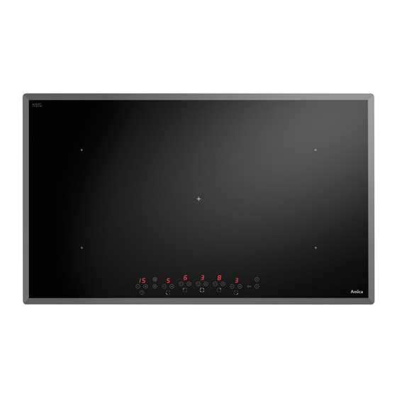
Page 9: Description Of The Appliance
DESCRIPTION OF THE APPLIANCE Description of PB*5VI502FTB5 plate Booster heating zone (back, right) Ø 210 mm Booster heating zone (back, left) Ø 210 mm Booster heating zone (centre) Ø 260 mm Booster heating zone (front, light) Ø 210 mm Booster heating zone (front, right) Ø... -
Page 10: Installation
INSTALLATION Installation of PB*5VI502FTB* plate ● The thickness of furniture surface should be between 28 and 40 mm, the depth of the surfa- ce – at least 600 mm. The surface should be flat and properly levelled. The surface should be sealed and protected against water spill and moisture from the side of the wall. - Page 11 INSTALLATION Fig. B 1 - table top 2 - Hob gasket 3 - ceramic plate Fig. C 25mm 5 10mm ÷ 30mm Fitted in the top of a carrying cupboard 500x10mm 5 10mm ÷ Fitted in a working top over an oven with ventilation 500x20mm Fitting the plate over non-ventilated oven is prohibited...
- Page 12 NSTALLATION Connecting the plate to the electrical system Note! The plate can be connected to the mains only by a qualified certified installer. Wilful adaptations or modifications to the electric system are prohibited. Guidelines for the installer The plate is provided with a terminal box enabling selection of proper connections for the given type of power supply.
- Page 13 NSTALLATION DIAGRAM OF POSSIBLE CONNECTIONS Notice! Voltage of heating elements is 230V Warning! In every type of connec- tion protective grounding has to be Recom- connected to terminal mended type of connec- tion cable 1 In the case of the 230V network, single phase connection with a neu- 3X 4 mm tral cable, bridges connect terminals...
-
Page 14: Operation
OPERATION Before first use • carefully clean the ceramic plate treating it as a glass surface, • when used for the first time the plate can give off a bit of a smell so switch on the ventilation system or open the window, •... - Page 15 OPERATION Detection of cookware on a cooking zone The pot detector is installed in plates equipped with the inductive field system. During opera- tion the pot detector automatically starts or stops the production of heat once a pot is put or removed from the plate, saving energy.
- Page 16 OPERATION Proper quality of pots is prerequisite for achieving proper performance of hob operation. Selection of cooking pots to be used in the induction zone ● Always use high quality pots with perfectly flat bottom. Using pots of this type prevents from the creation of sections of excessive temperature, where food sticks to the walls during cooking.
- Page 17 OPERATION Bottom of the cookware has to be flat for optimal temperature control by the induction module. Deep embossed logo or concave bottom of the cookware can interfere with the temperature control by the induction module and lead to overheating of the cookware.
- Page 18 OPERATION Control panel ● Once you connected the hob to the power network, all indicators will light up at the same time. The hob is ready for work. ● The hob is equipped with electronic sensors which you switch on by pressing them with the finger for at least 1 second.
- Page 19 OPERATION If within 10 seconds after the hob has been switched on no sensor has been activated, the heating zones switch off. A heating zone is active when on the hob display a figure or letter and a decimal point lights up, which means that the zone is ready for the heating power to be set up.
- Page 20 OPERATION Control of the Booster function Depending on the model, the cooking zones are paired vertically or crosswise. Total power is shared within the paired cooking zones. (see Fig.). If you attempt to enable the Booster function for both cooking zones simultaneously, the ma- ximum power available would be exceeded.
- Page 21 OPERATION Residual heat indicator When the hot heating zone is switched off, „H” is displayed as the signal meaning „heating zone is hot!”. During that time do not touch the heating zone as you may burn your- self and do not put on it any objects that are sensitive to heat! When the indicator goes off, you can touch the heating zone but beware that it still has...
- Page 22 OPERATION Automatic reheating function ● A given heating zone must be set to a power level (0). ● Pressing sensor (-) (3) results in switching to a power level (9). ● Then touch sensor (+) (2) of a given he- ating zone.
- Page 23 OPERATION Clock function The programming clock facilitates cooking as it can control how long heating zones are ac- tive. It can also be used as a timer. Switching the clock on The programming clock facilitates cooking as it can control how long heating zones are active.
- Page 24 OPERATION Changing the programmed cooking time At any point in the process of cooking you may change its pre-programmed duration. To do that repeat the same programming procedure as under the point „Switching on the clock” but do not set heating power using sensor (+)(2) or sensor (-)(3), but go directly to the proce- dure of clock activation by simultaneously pressing sensor (+)(5) and (-)(6) of the clock.
- Page 25 OPERATION Using clock as the timer The clock programming cooking time can be used as the timer only if the operation of he- ating zones is not time-controlled. Switching on the timer To set the timer, you should: ● simultaneously press sensor (+) (5) and sensor (-)(6) of the clock.
- Page 26 OPERATION Warm up function The warm up function keeps stable temperature of food on a heating zone. The selected heating zone is set to low heating power. This function will help you enjoy warm food, ready for serving at your convenience, that will not change taste or stick to the bottom of the pot. This function can be used to melt butter, chocolate, etc.
- Page 27 OPERATION The stop’n go function can be used for maximum 10 minutes. If the stop’n go function does not finish in this period, the panel sensor switches off. If control has been accidentally turned on by pressing the on/off sensor (1), the stop’n go function helps you to quickly restore the previous settings.
- Page 28 OPERATION Switching the heating zones off ● A heating zone can be switched off by simultaneous pressing of sensor (+) (2) and sensor (-) (3) or by reducing power to level (0) using sensor (-)(3). After approx. 10 seconds the he- ating zone is no longer active.
-
Page 29: Cleaning And Routine Maintenance
CLEANING AND ROUTINE MAINTENANCE Daily cleaning and proper maintenance have crucial impact on the durability of your ce ra- mic plate. Clean the ceramic plate observing the same rules as for glass. Never use abrasive or aggressive clean- ing agents, scrubbing powders or scratching sponges. -
Page 30: Emergency Procedure
EMERGENCY PROCEDURE Every time when emergency situation occurs you should: • switch off the working assemblies of the plate • disconnect power supply • call in the service • as some minor faults can be removed by the user in accordance with the be low specified instructions, before calling the Customer Service please go thro ugh the Table checking every point. - Page 31 EMERGENCY PROCEDURE PROBLEM CAUSE ACTION 7. Crack in the ceramic Danger! Immediately disconnect the ceramic plate plate from the mains (fuse) and call the nearest Customer Service Centre. 8. If the fault still remains Disconnect the ceramic plate from the mains (fuse) and call the nearest Customer Service Centre.
-
Page 32: Technical Data
TECHNICAL DATA Rated voltage 400V 3N~50 Hz Rated power: PB*5VI502FTB5 - cooking zone Booster: 4x Ø 210 mm 2,1kW/3,7kW - cooking zone Booster: 1xØ 260 mm 2,6kW/3,7kW Dimensions 870 x 518 x 50 Weight ca.14,5 kg Complies with EN 60335-1 and EN 60335-2-6 European standards. WARRANTY Warranty Warranty services according to the warranty card. - Page 36 For the UK: please call 01949 862012 01 88 2010...
Need help?
Do you have a question about the PB 5VI502FTB5 Series and is the answer not in the manual?
Questions and answers