Table of Contents
Advertisement
Quick Links
Advertisement
Table of Contents

Related Manuals for Dannmar B-200


Summary of Contents for Dannmar B-200
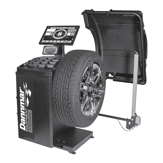
- Page 1 Dannmar EQUIPMENT...
- Page 3 INDEX Preface Pag. 2 Safety regulations Pag. 3 Carriage, hoisting, storage and transportation of the machine Pag. 3 Installation and switching on Pag. 5 Installation Pag. 6 Suspension of the use Pag. 6 Environmental information Pag. 6 Technical data Pag. 7 Routine maintenance of the wheel balancer Pag.
- Page 4 1. PREFACE Confirming the machine including the operation system, tools and accessories are operated normally and without any damage, you hand the machine to the customers and the machine will endue some period of guarantee. During this period, the manufacturer will repair the machine or the no-normal parts of the machine or machine itself free of charge but will not be responsible for the damage and wear and tear caused by the no-normal usage, transportation and maintenance.
-
Page 5: Safety Regulations
- RD:<85% (without condensation). - Environment temperature: 0° -50°C. - The floor of the ground should be enough solid to support the maximum weight of the machine. - The machine should not be used in the environment with the potential exploded factors. 2. - Page 6 Storage: The machine should not be exposed and should be covered with the plastic film. The machine should be stored in the warehouse of ventilation, dry and waterproof. In the storage area, the temperature should be controlled in the range of -10℃~55℃ and RH should be controlled in the range of 30%~90%.
-
Page 7: Installation And Switching On
4. INSTALLATION AND SWITCHING ON After unpacking wheel balancer, check the status of integrity and presence of faults, make the assembly of the component as shown in following pictures. 4.1 Electrical connection The standard version of the machine must be connected to a mains 110V Single Phase. The change of the power supply cannot be realized by the user;... -
Page 8: Installation
5. INSTALLATION 5.1 Installation area To install the machine you need a useful space on the basis of the information given in picture F5.1. Picture F5.1 From working position, the user must be able to view the machine and the surrounding area. INSTALLATION AREA MUST BE KEEP CLEAR BY POSSIBLE DANGEROUS OBJECTS. -
Page 9: Technical Data
Electrical and electronic equipment must never be disposed of in the usual municipal waste but must be separately collected for their proper treatment. Thus, the hazardous consequences that non-specific treatments of the substances contained in these products, or improper use of parts of them, may have on the environment or on human health are prevented. - Page 10 9. ROUTINE MAINTENANCE OF THE WHEEL BALANCER Warning The manufacturer declines all responsibility in the event of claims resulting from the use of non-original spare parts or accessories. Warning Unplug the machine from the socket and make sure that all moving parts have been locked before performing any adjustment or maintenance operation.
- Page 11 10. MONITOR The machine's control monitor is illustrated in figure F10.1. The control monitor is used by the operator to view the applied controls and the data entered with the keyboard. The same control panel displays the balancing results and machine messages. The control key functions are described in table T10.1.
-
Page 12: Stand By Led
11. KEYBOARD In this manual, the keys are numbered for convenience from [1] to [9] as shown in picture F11.1. The nine keys have only one primary function. Picture F11.1: Keyboard Table T11.1: Functions of the keys Pos. Description 1 – 2 – 3 - 4 Function selection keys. -
Page 13: Machine Calibration
13. MACHINE CALIBRATION To function properly, the machine must be calibrated. Calibration allows storing the mechanical and electrical parameters specific to each machine so provide the best balancing results. 13.1 Machine calibration for the CAR/SUV Wheel Type The calibration for the CAR wheel type and SUV wheel type is the same. To perform machine calibration, you must first provide for the following material: ... - Page 14 Extract the distance sensor and place it on the wheel as shown here. Read the distance value on the graduated scale. The distance value is always expressed in millimetres. Select which type of dimension to enter by pressing [2] or [4] on the keyboard and activate the wheel - machine distance insertion function by selecting which will turn green.
- Page 15 Enter reading pressing keyboard Lower the wheel guard: the machine will run a launch. By hand, turn the wheel in the direction marked by the arrow until you see 50 g on the left display. On the inner side of the wheel, at 12 o'clock, apply the 50 g weight. Lower the wheel guard: the machine will run a launch.
- Page 16 Calibration is finished: the machine automatically exits the calibration program and returns to the NORMAL mode, ready to perform the balancing. At any time it is possible to exit the calibration procedure by pressing [5] key. 13.2 Machine calibration for the MOTO wheel type The calibration for MOTO wheel type (motorcycle wheels) is completely separated from CAR/SUV wheel type because in the calibration for MOTO a specific adaptor for motorcycle wheels is used If the calibration for MOTO wheel type has not been done and the user try to spin the wheel for balancing in the MOTO wheel type...
- Page 17 At the end of the launch, the machine will display the message shown here. Apply the calibration weight to the inner side, as shown. The calibration weight must be applied on the hole marked with the “CAL” inscription. Lower the wheel guard: the machine will run a launch. Move the motorcycle adaptor to a stable vertical position with the calibration weight at the top as shown in the figure.
- Page 18 14. USE OF THE MACHINE IN NORMAL MODE The machine allows the choice between eight different Program Type of balancing as listed in table T14.1. Table T14.1: Program Types available Program Type Wheel Weight position along the rim Automatic Notes material selection acquisition...
- Page 19 Picture F14.1: Position of the weights in the various Program Types along the section of the rim Angular position of the balancing weights in the several Program Type is shown in table T14.2. Table T14.2: Angular position of the balancing weights in the various Program Types Program Type STD, Machine...
- Page 20 14.2 Wheel types The machine allows choosing between three different Wheel Types as listed in table T14.3. Table T14.3: Wheel Types to select Wheel Type Vehicle Notes Auto-vehicles Default power on Motorbikes Forcibly set the ALU1 Program Type MOTO Off-Road vehicles Not suitable for balancing truck wheels To select a specific wheel type, proceed as follows: Description...
- Page 21 14.2.1 CAR wheel type The selection of the CAR Wheel Type allows the balancing of wheels of auto-vehicles. To select the CAR wheel type, proceed as follows: Description Press [2] or [4] from the keyboard and select the icon relative to the program to be used. Activate the AUTO program by selecting (by default at start-up) which will turn green.
- Page 22 To acquire automatically the geometrical wheel data by Distance/Diameter and Width sensors, it is necessary to keep the same reference points on the rim as Program Type ALU1. Extension for Furthermore, when the Wheel Type MOTO is selected, the actual distance value sensor is increased of 150 mm due to the extension length for the Diameter/Distance sensor.
- Page 23 14.2.3 OFF ROAD wheel type The selection of SUV wheel type allows the balancing of wheels for off-road vehicles. These vehicles are generally equipped with wheels that are larger than normal and the tyre is relatively large compared to the diameter of the rim (that means not the low profile or super low profile types).
- Page 24 14.3 Entering wheel dimensions The dimensions of the wheel to balance can be entered in automatic way (partially or completely). 14.3.1 Automatic acquisition of the wheel dimensions for the STD and ALU1, 2, 3, 4, 5 Program Types To automatically introduce the wheel size data, proceed as follows: Description Fit the wheel on the shaft and tighten with the ring nut.
- Page 25 14.3.2 Automatic acquisition of the wheel dimensions for the ALS1, ALS2 program types To automatically enter the dimensions of the wheel in the ALS1 and ALS2 program types proceed as follows: Description Fit the wheel on the shaft and tighten with the ring nut. Press [2] or [4] from the keyboard and select the icon relative to the programme to be used.
- Page 26 Wait to hear the long acquisition beep and then set the Distance/Diameter sensor back to the rest position. During acquisition the distance and diameter values are displayed on the wheel dimension data band. Acquisition of the internal plane is confirmed by a long beep followed by a short beep. Extract the Distance/Diameter sensor and place it on the plane chosen as the Automatic acquisition...
- Page 27 14.4.1 Balancing spin To perform the balancing spin, proceed as follows: Description Lower the wheel guard to run the balancing launch. Once the spin cycle is completed, the imbalance values calculated, according to the balancing planes chosen, will be displayed. The machine also automatically sets the Search mode of the balancing planes.
- Page 28 Release the wheel and turn it by hand until all of the external imbalance position leds light up. Slowly extract the sensor until you hear the continuous beep indicating that the external balancing plane has been reached. The red band represents the application point of the external weight.
- Page 29 If the wheel's static imbalance is less than 12 grams, the ERR 055 error message will appear and it will automatically exit the optimisation programme. If, on the other hand the wheel's static imbalance is greater than 12 grams, the machine will start the OPTIMISATION programme.
- Page 30 16. HIDDEN WEIGHTS PROGRAM This program divides the external weight “Pe” in two weights W1 and W2 (smaller than the initial external weight W) located in any two positions selected by the operator. The two weights W1 and W2 must form a maximum angle of 120° including the external weight “Pe”, as shown in picture F16.1. Picture F16.1: Hidden Weights Program: valid and invalid conditions for use in this example the balancing external weight Pe is indicated at 12 o’clock (H12) but can be at 6 o’clock (H6) or at 3 o’clock (H3): see text The Hidden Weights program is used for aluminum rims when:...
- Page 31 Activate the HIDDEN WEIGHTS programme by selecting (which will be outlined in green) and confirm by pressing [6] on the keyboard. If the wheel is balanced on the external side, the machine will display error code ERR 050 to signal that the operation is not allowed. Manually rotate the wheel anticlockwise and with the sensor behind the first selected spoke.
- Page 32 17. SECOND OPERATOR The machine has two separate memories allowing two operators to work simultaneously with different settings. This feature can make operations at the workshop quicker because when, for example, an operator is busy with removing or remounting a tire, the other operator can use the machine to perform balancing operations and vice versa. In this manual, the two operators are defined as operator 1 and operator 2.
-
Page 33: Utility Programs
18. UTILITY PROGRAMS Utility programs are available only in NORMAL mode. 18.1 Selecting the imbalance display resolution The machine has two wheel imbalance display resolutions. The two resolutions are defined as X1 (high resolution) and X5 (low resolution). The resolution with which the imbalances of the wheel are displayed varies depending on the unit of weight as indicated in table T18.1. - Page 34 18.2 Selection of the static imbalance display To display STATIC IMBALANCE proceed as follows: Description Display Press [2] or [4] from the keyboard and select the icon relative to the program to be used. Activate the DYNAMIC program by selecting (by default at start- up) which will turn green.
- Page 35 18.3 Electromagnetic clamping brake The electromagnetic clamping brake is useful to block the wheel in any position and to simplify some operations such as the application or removal of balancing weights. The electromagnetic clamping brake is also used in the automatic or manual stopping of the wheel on imbalance positions described in chapter 18.5 Wheel stop procedure on the positions of imbalance.
- Page 36 18.4 Illuminator The illuminator is quite useful because it allows shedding light on the internal part of the rim. To activate and/or deactivate the ILLUMINATOR proceed as follows: Description Display Press [2] or [4] from the keyboard and select the icon relative to the program to be used. Activate the ILLUMINATOR ENABLING program by selecting default at start-up) which will turn green.
- Page 37 18.5 Wheel stop procedure on the positions of imbalance Machines equipped with the electromagnetic clamping brake are capable of automatically stopping the wheel at the first imbalance angular position that is reached during rotation. This allows the operator to have the wheel in position ready for the application of the balancing weight thus increasing work and productivity speeds.
- Page 38 18.6 Select grams/ounces To modify the current UNIT OF MEASUREMENT, proceed as follows: Description Press [2] or [4] from the keyboard and select the icon relative to the programme to be used. Activate the work program in GRAMS by selecting (by default at start-up) which will turn green.
- Page 39 18.7 Select inches/millimeters To modify the UNIT OF MEASUREMENT OF WHEEL DIMENSIONS, proceed as follows: Description Press [2] or [4] from the keyboard and select the icon relative to the program to be used. Activate the work program IN INCHES by selecting (by default at start-up) which will turn green.
- Page 40 18.8 Select balancing weights material Fe/Zn or Pb The selection of the material type slightly changes the balancing results because the weights in Iron/Zinc are lighter than those in Lead and therefore are larger. The machine takes account of these differences when calculating the imbalance. Table T18.3: Balancing weights materials Option Type of balancing weight material...
-
Page 41: Error Codes
19. ERROR CODES The Error signal is always accompanied by a triple beep indicating that the machine cannot run the command given by the operator, or, during operation, conditions were encountered that prevent the action in progress from continuing. The machine reports error conditions by displaying an outline of the description of the cause of the error. The list of error codes and description outlines is provided in table T19.1. -
Page 42: Operator Action
The error code can be exited in the following ways: OPERATOR The machine exits from the error code display when the operator presses any key. CONFIRMATION The machine exits from the error code display when the operator performs an action linked to said OPERATOR ACTION error code (for example, ERR 016 brings the Distance sensor back to the rest position). - Page 43 Additional note: After LAS( laser positioning function) is activated, under ALS modes, operator can use internal automatic gauge to measure and designate the stick on weight positions, according to the indication of the laser reference line to stick on the weights at 6 o’clock right under the balancer shaft. Pag.
- Page 44 Dannmar EQUIPMENT...
Need help?
Do you have a question about the B-200 and is the answer not in the manual?
Questions and answers