Table of Contents
Advertisement
Installation and Operation Manual
Manual P/N 5900261 — Manual Revision A1 — Released January 2021
Model:
• DB-70
Designed and engineered in Southern California, USA. Made in China.
⚠
DANGER
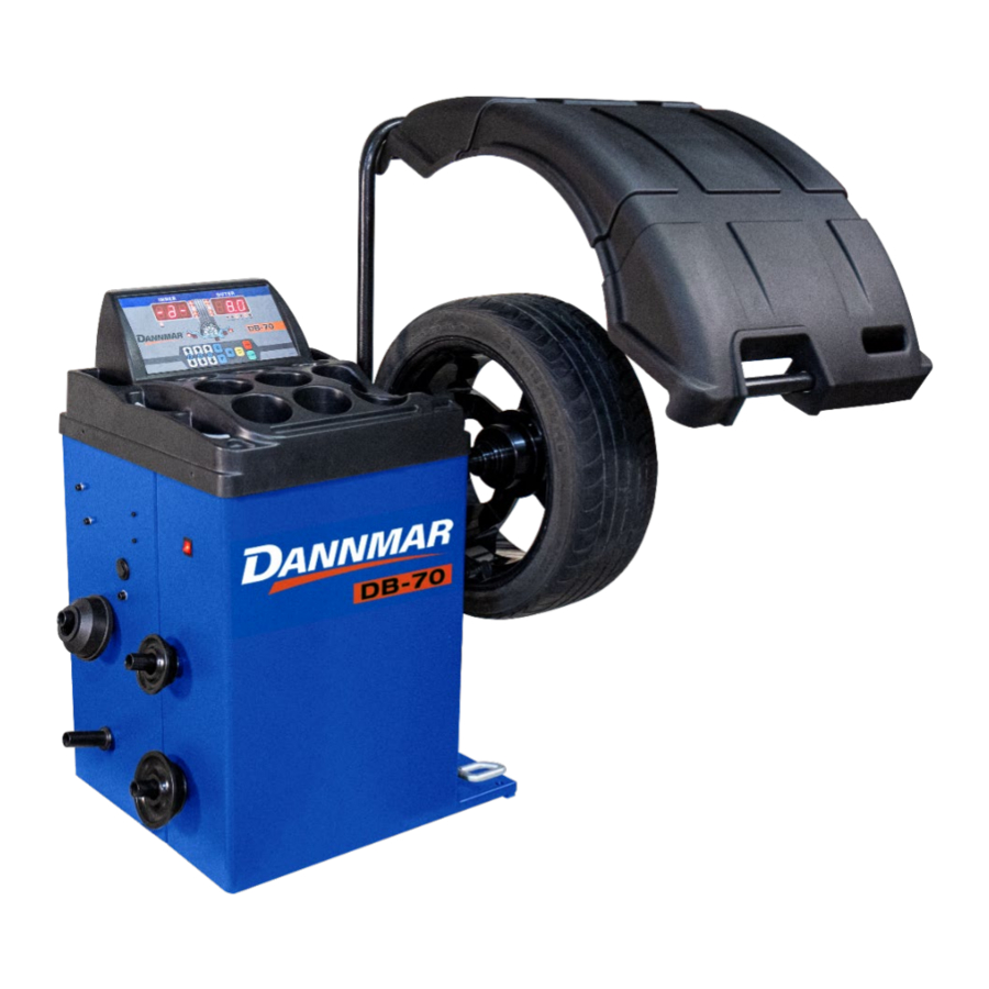
Automatic Wheel Balancer
Read the
this product. Failure to follow the instructions and safety
precautions in this manual can result in serious injury or
death. Make sure all other operators also read this manual.
Keep the manual near the product for future reference. By
proceeding with setup and operation, you agree that
you fully understand the contents of this manual and
assume full responsibility for product use.
enTire
contents of this manual
1645 Lemonwood Dr.
Santa Paula, CA 93060 USA
Telephone: (877) 432-6627
Dannmar.com
before
using
Advertisement
Table of Contents

Related Manuals for Dannmar DB-70


Summary of Contents for Dannmar DB-70
- Page 1 Telephone: (877) 432-6627 Dannmar.com Automatic Wheel Balancer Installation and Operation Manual Manual P/N 5900261 — Manual Revision A1 — Released January 2021 Model: • DB-70 Designed and engineered in Southern California, USA. Made in China. ⚠ enTire before contents of this manual...
- Page 2 Feel free to contact us at any time to get the latest information about any product: Dannmar.com. Warranty. The BendPak Dannmar warranty is more than a commitment to you: it is also a commitment to the value of your new product. For full warranty details, contact your nearest BendPak Dannmar dealer or visit dannmar.com/support/warranty/.
-
Page 3: Table Of Contents
Technical support and service for your Wheel Balancing Machine is available from your distributor or by calling Dannmar at (877) 432-6627. You may also call regarding parts replacement (please have the serial number and model number of your unit available). -
Page 4: Shipping Information
Do not make any modifications to the product; this voids the warranty and increases the chances Do not modify any safety-related features in any way. of injury or property damage. DB-70 Automatic Wheel Balancer P/N 5900261 — Rev. A1 — January 2021... - Page 5 Make a visual inspection of the Wheel Balancing Machine every day. Do not use the product if you find any missing or damaged parts. Instead, take the Wheel Balancing Machine out of service, then contact an authorized repair facility, your distributor, or Dannmar at (877) 432-6627. •...
-
Page 6: Components
Quick Nut. Holds the wheel on the Shaft. Mounting Cones and Cups. Supporting a wide range of Tire sizes. Caliper. Used to measure the wheel width. Spacer Ring. Used for larger wheels only. DB-70 Automatic Wheel Balancer P/N 5900261 — Rev. A1 — January 2021... - Page 7 Wheels, so you need to know where you want to put the Weights and select the appropriate ALU Mode. ALU Modes generally use Adhesive Weights, which are less visible than Clip-On Weights. DB-70 Automatic Wheel Balancer P/N 5900261 — Rev. A1 — January 2021...
- Page 8 F button on the Control Panel to see specific values. Q: What do I do if I have a problem with the Balancer that I cannot solve? A: Contact Dannmar; we are here to help. Using a web browser, visit the Dannmar Support website.
-
Page 9: Specifications
*Comes from the factory configured for 110 VAC operation. The Balancer may be switched to 220 VAC. Refer to Connecting to Power for instructions; Licensed Electrician is required to switch the Balancer to 220 VAC. Specifications subject to change without notice. DB-70 Automatic Wheel Balancer P/N 5900261 — Rev. A1 — January 2021... -
Page 10: Installation Checklist
3. Verify that there is a power source available at the installation location. Make arrangements for an electrician, if required. ☐ 4. Make sure you have the necessary Tools. ☐ 5. Make sure there is adequate clearance around and above the DB-70. ☐ 6. Unpack the Components. ☐ 7. Connect the matcher to the Balancer shaft. -
Page 11: Installation
Installation This section describes how to install the Dannmar Wheel Balancer. Perform the tasks in the order presented. Installation Safety Rules Pay attention at all times during installation. Use appropriate tools and equipment. Stay clear of moving parts. Keep hands and fingers away from pinch points. - Page 12 Power Source. The Wheel Balancing Machine needs to be near an appropriate 110 or 220 VAC power source. • Floor. The Wheel Balancing Machine requires a flat, concrete floor. • Clearance. The DB-70 needs 5 m space around it. Refer to Clearance for more information. •...
- Page 13 However, for safety purposes, only the Operator Balancing Machine. should be within 30 feet of the Wheel Balancing Machine while it is in use. Top view. Not necessarily to scale. Not all components shown. DB-70 Automatic Wheel Balancer P/N 5900261 — Rev. A1 — January 2021...
- Page 14 Unpacking Dannmar recommends unpacking the Wheel Balancing Machine as close as possible to its permanent location. The less you have to move things around, the smoother your unpacking and installing will be. Many of the Wheel Balancing Machine components have been greased for shipping.
- Page 15 Install the six Clip Nuts on the cabinet and place the tray over the cabinet. Secure with the six M6 x 20 Hex Socket Head Screws. ⚠ NOT over-tighten the screws CAUTION . Cracking of the plastic tray will result. DB-70 Automatic Wheel Balancer P/N 5900261 — Rev. A1 — January 2021...
- Page 16 Use a drill bit that is the same diameter as the Anchor Bolt. So, if you are using an 3/8 in diameter Anchor Bolt, for example, use a 3/8 in diameter drill bit. DB-70 Automatic Wheel Balancer P/N 5900261 — Rev. A1 — January 2021...
- Page 17 4. Vacuum each hole to remove debris Dannmar recommends using a wire brush and a vacuum to get the hole very clean. ream the hole. Do make the hole any wider than the drill bit made it. 5. Place the Washer on the anchor and thread the nut partially down the anchor, then insert the Anchor Bolt into the hole.
- Page 18 110 VAC plug on the end of the Power Cord and attach a 250 VAC NEMA 30A, 2-Pole, 3-Wire plug. The DB-70 does not come with this plug. You Do not change the 110 VAC plug to a 220 VAC plug unless you must supply your own.
- Page 19 In the On position, the Balancer will start a test cycle when the Tire cover is closed and stop it when open. • In the Off position the Tire cover must be manually closed and the test cycle begun by pressing Start on the front panel. DB-70 Automatic Wheel Balancer P/N 5900261 — Rev. A1 — January 2021...
-
Page 20: Operation
• ANSI-approved When using the Wheel Balancing Machine, the operator must wear eye protection at all times : safety glasses, a face shield, or protective goggles. DB-70 Automatic Wheel Balancer P/N 5900261 — Rev. A1 — January 2021... - Page 21 Keep the work area clean and well lit. Dirty, cluttered, and dark work areas increase the chances of an accident occurring. • Do not access the inside of the unit unless instructed to do so by Dannmar Support. ⚠ WARNING Do not use the Wheel Balancing Machine in a wet environment or expose it to rain or excess moisture.
- Page 22 Outer Display Window and slowly rotate the wheel until all the lights to the left of the Window are lit. Laser. Not required on the DB-70. System Status Indicators. Located under the Outer Display Window, these indicate •...
- Page 23 F + B Changes width display from millimeters to inches. F + D Manually inputs the D2 value of the wheel. F + STOP Enters System parameter settings. DB-70 Automatic Wheel Balancer P/N 5900261 — Rev. A1 — January 2021...
- Page 24 Do not hammer on the Quick Nut to tighten. This will damage the Quick Nut, which is not covered under the warranty. Front- Cone Mount. The preferred method, as it generally produces the most accurate balancing results. DB-70 Automatic Wheel Balancer P/N 5900261 — Rev. A1 — January 2021...
- Page 25 8. Remove any weights from previous balancing efforts. 9. Visually inspect the wheel mounting surface for deformations or damage that would prevent the wheel from riding on the Shaft correctly. DB-70 Automatic Wheel Balancer P/N 5900261 — Rev. A1 — January 2021...
- Page 26 5. Slowly slide the Inner Measurement Arm out from the side of the Balancer and touch the rim of the wheel. You will see the inner distance measurement and the wheel diameter value appear in the Outer Display Window. DB-70 Automatic Wheel Balancer P/N 5900261 — Rev. A1 — January 2021...
- Page 27 The Balancer will spin and weight to be added for correction will appear, but without correct measurements it is virtually guaranteed that the balance will be accurate. DB-70 Automatic Wheel Balancer P/N 5900261 — Rev. A1 — January 2021...
- Page 28 ALU 4 - The ALU 4 balance mode clamps balance correction weights on the inner edge and utilizes adhesive weights on the outer plane outside the spoke. DB-70 Automatic Wheel Balancer P/N 5900261 — Rev. A1 — January 2021...
- Page 29 B. The value should appear in the Outer Window. 9. When all three measurements are correct, you are done entering measurements. DB-70 Automatic Wheel Balancer P/N 5900261 — Rev. A1 — January 2021...
- Page 30 5. Turn on the Balancer. The power switch is located on the left-hand side near the front of the cabinet. The display should be flashing, and –a- will appear in the Inner Display Window. DB-70 Automatic Wheel Balancer P/N 5900261 — Rev. A1 — January 2021...
- Page 31 17. Lower the Tire Cover to spin and test the Wheel again. The Wheel is balanced when the Display Windows show 0.0. It may take more than one time adding weights to get to 0.0 | 0.0. DB-70 Automatic Wheel Balancer P/N 5900261 — Rev. A1 — January 2021...
- Page 32 5. Turn the Balancer Off and then back On, to reset. The display should be flashing, and –a- will appear in the Inner Display Window. DB-70 Automatic Wheel Balancer P/N 5900261 — Rev. A1 — January 2021...
- Page 33 (a2 and d2), then places the parameters into the Balancer’s memory. You may also enter the values manually using the A and D keys. DB-70 Automatic Wheel Balancer P/N 5900261 — Rev. A1 — January 2021...
- Page 34 Wheel (12 o’clock high) on the Center Plane for ALU1. If you are adding Adhesive Weights with multiple sections, center them on Top Dead Center. u. Release the Brake Pedal. v. Lower the Tire Cover to spin the Wheel again. DB-70 Automatic Wheel Balancer P/N 5900261 — Rev. A1 — January 2021...
- Page 35 B. The value should appear in the Outer Display Window. When all three measurements are correct, you are done entering measurements. h. Close the Tire Cover; the Wheel spins briefly. DB-70 Automatic Wheel Balancer P/N 5900261 — Rev. A1 — January 2021...
- Page 36 The Wheel is balanced when both the Inner and Outer Windows show 0.0. It may take more than one time adding weights to get to 0.0 | 0.0. DB-70 Automatic Wheel Balancer P/N 5900261 — Rev. A1 — January 2021...
- Page 37 Balancer to the wheel and the wheel diameter (a1 and d1), then places the parameters into the Balancer’s memory. You may also enter the values manually using the A and D keys. DB-70 Automatic Wheel Balancer P/N 5900261 — Rev. A1 — January 2021...
- Page 38 If the value is 00, you do not need to add weight to the Inner Edge. • If there is a value—.25, for example—you need to add that amount of Weight to the Inner edge. DB-70 Automatic Wheel Balancer P/N 5900261 — Rev. A1 — January 2021...
- Page 39 Wheel, the longer the Adhesive Weight stays in place. d. Mount the Wheel on the Balancer. Refer to Mounting a Wheel for mounting instructions, if needed. DB-70 Automatic Wheel Balancer P/N 5900261 — Rev. A1 — January 2021...
- Page 40 Adhesive Weight with multiple sections, center them on Top Dead Center. p. Check the value on the Outer Display Window: • If the value is 0.0, you do not need to add Weight to the Outer Plane. DB-70 Automatic Wheel Balancer P/N 5900261 — Rev. A1 — January 2021...
- Page 41 Input the wheel parameters. Slide the inner distance arm to touch the Inner Plane and hold it there to automatically determine the distance from the side of the Balancer and DB-70 Automatic Wheel Balancer P/N 5900261 — Rev. A1 — January 2021...
- Page 42 Manually turn the Wheel, watching the indicators to the left of the Outer Display Window. The Indicators light up or go out as you move the Wheel. DB-70 Automatic Wheel Balancer P/N 5900261 — Rev. A1 — January 2021...
- Page 43 Choose the position for the inner correction weights and input the a1 (Wheel Plane) and d1 (Wheel Diameter) parameters using the inner measuring arm held to the inner plane until you hear a beep. DB-70 Automatic Wheel Balancer P/N 5900261 — Rev. A1 — January 2021...
- Page 44 The Wheel is balanced when both the Inner and Outer Windows show 0.0. It may take more than one time adding weights to get to 0.0 | 0.0. DB-70 Automatic Wheel Balancer P/N 5900261 — Rev. A1 — January 2021...
- Page 45 13. Hold the inner arm against the center plane behind the second spoke. 14. Press OPT SP to confirm the selection. 15. Prepare the ½ the required weight to be placed behind spoke. DB-70 Automatic Wheel Balancer P/N 5900261 — Rev. A1 — January 2021...
- Page 46 Cone, and the Rim at the Tire. The Mark on the Tire itself will be 180° from the other Marks. 6. Lower the Tire cover or press the Start button. DB-70 Automatic Wheel Balancer P/N 5900261 — Rev. A1 — January 2021...
- Page 47 9. Start the balancing machine by pressing the Start key. When the motor shuts off, use the brake to bring the wheel to a stop. 10. The calibration is complete and the unbalanced amount of the Wheel at the last rotation is displayed. DB-70 Automatic Wheel Balancer P/N 5900261 — Rev. A1 — January 2021...
- Page 48 When the lengthened distance arm in set is set to on the default balancing mode is set to STA Static for motorcycle Wheel Balancing. When operating the Balancer the display shows: DB-70 Automatic Wheel Balancer P/N 5900261 — Rev. A1 — January 2021...
-
Page 49: Maintenance
⚠ WARNING Do not operate your Balancer if you find issues; instead, take the unit out of service, then contact your dealer, visit dannmar.com/support, call Dannmar at (877) 432-6627, or email support@dannmar.com. DB-70 Automatic Wheel Balancer... -
Page 50: Troubleshooting
Tire is slipping on the Wheel (possible Tire Changer issue); have Tire remounted and then rebalanced. Stones or other objects caught in Tire tread; remove the objects, rebalance if necessary. DB-70 Automatic Wheel Balancer P/N 5900261 — Rev. A1 — January 2021... - Page 51 Replace the power board. Err-20 Integrated circuit damage. Replace CPU board. If you continue to have problems with your Wheel Balancer, visit dannmar.com/support/ call Dannmar at (877) 432-6627, or email Support@dannmar.com. DB-70 Automatic Wheel Balancer P/N 5900261 — Rev. A1 — January 2021...
-
Page 52: Labels
Labels DB-70 Automatic Wheel Balancer P/N 5900261 — Rev. A1 — January 2021... - Page 53 DB-70 Automatic Wheel Balancer P/N 5900261 — Rev. A1 — January 2021...
-
Page 54: Parts
SHCS M6 x 25 Washer Φ6 Washer, Φ6 Split Lock Hex Nut M6 Cabinet Dam-board Cross Recessed Pan Head Screw M4 x 16 Display Board 5327132 Cone hangar 5525251 On-Off switch DB-70 Automatic Wheel Balancer P/N 5900261 — Rev. A1 — January 2021... - Page 55 SHCS M4 x 12 Spindle Bushing Welding Parts Snap Ring Φ30 Bearing Snap Ring Φ62 Bearing Circlip for Hole Φ62 Threaded Shaft Matcher 5327182 SHCS M14 x 240 DB-70 Automatic Wheel Balancer P/N 5900261 — Rev. A1 — January 2021...
- Page 56 Pressure Sensor Assy. Parts List Part Number Description Hexagon Bolt M10 x 40 Washer Φ10 Motor Pulley 5327140 Photoelectric Tooth Washer, Φ4 Split Lock 5327139 SHCS M4 x 12 DB-70 Automatic Wheel Balancer P/N 5900261 — Rev. A1 — January 2021...
- Page 57 Pad Φ8 HHB M8 x 30 5327145 Flat Key 5 x 5 x 30 5327144 Motor Belt Pulley SHCS M6 x 16 Spring Washer Φ6 Washer Φ6 V- Belt DB-70 Automatic Wheel Balancer P/N 5900261 — Rev. A1 — January 2021...
- Page 58 Encoder Board Parts List Part Number Description Cross recessed Pan Head Screw M3 x 10 Washer M4 Encoder (Encored) Board Encoder (Encored) Bracket 5327145 SHCS M4 x 8 5327144 Washer M4 DB-70 Automatic Wheel Balancer P/N 5900261 — Rev. A1 — January 2021...
- Page 59 Hexagon Socket Set with Flat Point M8 x 40 Spindle Nylon Cover Lock Nut (Caulking Nut) M10 SHCS M10 x 45 Snap Ring Injection Molded Tire Cover BRKT DB-70 Automatic Wheel Balancer P/N 5900261 — Rev. A1 — January 2021...
- Page 60 CPU Board Box Cover Cross Recessed Pan Head Tapping Screw ST 2.2 x 6.5 5324147 Brake resistance Digital Tube CPU Power Board CPU Board Cassette Holder Recess Head Screw DB-70 Automatic Wheel Balancer P/N 5900261 — Rev. A1 — January 2021...
- Page 61 Inner Distance Arm Assy. DB-70 Automatic Wheel Balancer P/N 5900261 — Rev. A1 — January 2021...
- Page 62 Cross Recessed Pan Head Screw M3 x 8 D Value Measurer Board Rack Axis End Sliding Block Thread Bushing Pivot Bush Unit Pull Rod Bent Rod End Compression Spring SHCS M5 x 20 DB-70 Automatic Wheel Balancer P/N 5900261 — Rev. A1 — January 2021...
- Page 63 Quick Release Nut 5327720 Allen Wrench 5346425 Wheel Weight Tool (Weight Hammer Pliers) Cone Spring (Tower of Spring) 5402187 Wheel Width Caliper Anchor Bolt (Expansion Bolt) M8 x 100 DB-70 Automatic Wheel Balancer P/N 5900261 — Rev. A1 — January 2021...
- Page 64 Wiring Assy. Wiring Assy. Parts List Part Number Description Power Line Gauge Wire Cover Switch Wire Measuring Arm Harness (Draw the Ruler to Connect the Tire) Ground Electrode DB-70 Automatic Wheel Balancer P/N 5900261 — Rev. A1 — January 2021...
- Page 65 Wiring DB-70 Automatic Wheel Balancer P/N 5900261 — Rev. A1 — January 2021...
-
Page 66: Maintenance Log
Maintenance Log DB-70 Automatic Wheel Balancer P/N 5900261 — Rev. A1 — January 2021... - Page 67 Maintenance Log DB-70 Dynamic Wheel Balancing Machine P/N 5900261 — Rev. A1 — January 2021...
- Page 68 1645 Lemonwood Drive Santa Paula, CA 93060 USA © 2021 BendPak, Inc. All rights reserved. Dannmar.com...
Need help?
Do you have a question about the DB-70 and is the answer not in the manual?
Questions and answers