Table of Contents
Advertisement
Quick Links
4FA021301
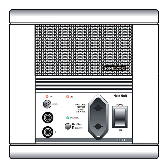
1 - Audio output level indicator LED.
2 - Audio output level adjustment.
3 - Signal input connector (left).
4 - Signal input connector (right).
5 - Telecontrolled socket.
6 - Power switch.
7 - LOCAL/REMOTE telecontrol selector switch.
8 - Led indicator showing activation of telecontrol (green)
9 - Led indicator showing connection to mains.
10 - Connection strips to sound system installation.
11 - Connection strip to mains.
12 - Mono/Stereo switch
13 - Grille
14 - Frame (delivered separately)
DESCRIPTION
Unit with 1 stereo channel. It has manual audio level adjustment. With
optimum output level indicator LED.
GENERAL CHARACTERISTICS
-
Audio inputs with CINCH connectors (3,4).
-
Internal Mono/Stereo switch (12)
-
Built-in 60 VA supply source, supplying 16 V DC with electronic fi lter
for general supply of the system (terminal 2).
-
Mains input voltage: 230V AC (50/60 Hz) P3271
115V AC (50/60 Hz) P3272
-
Electronic protection against short-circuits and overloads in the
supply.
-
Telecontrol (with selector switch 7 in REMOTE position). When any
of the system controls are activated, socket (5) automatically
connects supplying 220V to the sound source. When all the controls
of the system are switched off this socket disconnects
automatically, switching off the sound source, with the subsequent
energy saving.
-
Local control (with selector switch 7 in LOCAL position). To switch on
the outer sound source manually, regardless of the state of the system
controls.
-
Two-pin power switch (6) to totally disconnect the system.
LED indicating operation of the unit (9).
-
Incorpora un fusible de protección de la entrada de red y base telecon-
trolada, y una protección de la salida de alimentación en baja tensión
para la instalación (además de la protección electrónica).
-
Rejilla aireacion con ventilador interno bajo ruido y con conexión
automática
-
All the components used for connection to the mains are offi cially
approved, complying with the strictest safety regulations.
-
Internal fan with automatic activation.
CONNECTION
The main unit will be installed in a P9002 flush-mount box or in a P9026
surface-mount box, preferably next to the sound source.
The connection to the 220/230V mains will be done with at least 1
sq.mm. section wires and double insulation. For safety reasons the earth
connection must also be connected.
MAIN UNIT - 1 stereo channel P3271 - P3272
NOTE: It is advisable for the cables of the electricity supply mains
to be as far away as possible from the unit circuit.
The connection to the distribution line can be done with wires, P9910 ó
P9940 (in the case of paging or intercom) for the supply and the music
channels. The other wires can be used if required for any of the auxiliary
functions.
TERMINALS:
F- Phase (P3271 - 220/230 V AC) (P3272 - 115/125 V AC)
N- Neutral (P3271 - 220/230 V AC) (P3272 - 115/125 V AC)
- Earth (protection conductor)
2- Positive - voltage output 16 V DC nominal/4 A maximum
4- Negative - Supply and signal ground.
15- Audio output - Channel 1 Left - 3 V RMS max.
16- Audio output - Channel 1 Right - 3 V RMS max.
R- Auxiliary terminal for telecontrol.
must be disconnected to make sure the connection is made with
the correct safety guarantees. Under no circumstances must the
unit be handled outside its flush box, connected to the alternating
current network. Make sure that you have made the earth
connection correctly.
CONNECTION TO MAINS:
terminal strip (11) (to the right of the mains switch), through the holes
situated on the rear circuit protector of the unit, and tighten the screws
of the strip. Make sure they are well-tight and that no wire thread is
outside the holes.
CONNECTION TO THE SOUND LINE:
line to the strip (10), passing the wires through the groove of the circuit
protector, with care not to mistake the order. Make sure the screws are
tightened correctly.
CONNECTION TO THE SOUND EQUIPMENT:
to the telecontrolled mains socket (5). Connect the audio output of the
equipment to the CINCH connectors (3,4) on the front of the unit. To do
this use a stereo connection wire (not supplied with the unit) with CINCH
connectors on one end and with the connectors used in the music
equipment.
NOTE: Terminal R permits the remote operation of the telecontrol. It is
used when two or more units are installed together. By interconnecting
their R terminals, if the telecontrol of one of the units trips that of the other
trips at the same time.
IMPORTANT NOTE: Before connecting this unit to the
electricity supply mains, the power switch of that system
Insert the mains and the earth wires into the
Connect the wires of the sound
Connect the mains plug
Advertisement
Table of Contents

Related Manuals for Sonelco P3271


Summary of Contents for Sonelco P3271
- Page 1 TERMINALS: Audio inputs with CINCH connectors (3,4). F- Phase (P3271 - 220/230 V AC) (P3272 - 115/125 V AC) Internal Mono/Stereo switch (12) N- Neutral (P3271 - 220/230 V AC) (P3272 - 115/125 V AC) Built-in 60 VA supply source, supplying 16 V DC with electronic fi lter - Earth (protection conductor) for general supply of the system (terminal 2).
- Page 2 INSTALLATION RECOMMENDATIONS DOUBLE FRONT FRAME + SUPPLEMENT FOR "SONELCO" BOXES: In Sonelco’s General Diagrams, you will find connection diagrams and During the installation of main units and power supply units, it is advisa- cable sections recommended for the audio installation.
Need help?
Do you have a question about the P3271 and is the answer not in the manual?
Questions and answers