
Related Manuals for Samsung AC MN4PKH Series


Summary of Contents for Samsung AC MN4PKH Series
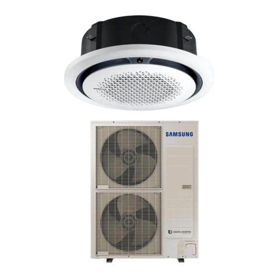
- Page 1 Air conditioner Installation manual MN4PKH Thank you for purchasing this Samsung air conditioner. Before operating this unit, please read this manual carefully and retain it for future reference.
-
Page 2: Table Of Contents
Contents Safety Information Installation Procedure Step 1 Checking and preparing accessories Step 2 Choosing the installation location Step 3 Optional: Insulating the body of the indoor unit Step 4 Installing the indoor unit Step 5 Purging inert gas from the indoor unit Step 6 Cutting and flaring the pipes Step 7 Connecting the assembly pipes to the refrigerant pipes Step 8 Performing the gas leak test... -
Page 3: Safety Information
Safety Information WARNING CAUTION WARNING General information WARNING Installing the unit WARNING IMPORTANT: When installing the unit, always remember to connect first the refrigerant tubes, then the electrical lines. English... - Page 4 Safety Information – – CAUTION Make sure that you earth the cables. Install the circuit breaker. Power supply line, fuse or circuit Make sure that the condensed water dripping from the drain hose runs out properly and safely. breaker Install the power cable and communication cable of the indoor and outdoor unit at least 1m away from the WARNING electric appliance.
-
Page 5: Installation Procedure
Installation Procedure Step 1 Checking and preparing Step 2 Choosing the installation accessories location Installation location requirements Insulation pipe Cable-tie Drain hose Installation manual Clamp User manual Installation template Dimension gauge English... - Page 6 Installation Procedure Indoor unit dimensions Category Square panel Circular panel 1050 1000 Front Ceiling opening dimension 960 (950 - 960) Drain hose Refrigerant connector pipe Large+, Large Wire insert hole Drain hose Refrigerant connector pipe Small Wire insert hole ø100 Common Square panel Circular panel...
- Page 7 Model Chassis Net dimension (WxDxH) Liquid pipe connection inch Gas pipe connection inch Drain hose connection 1050 Inspection hole Refrigerant pipe Indoor unit display Connection part of the ø1010 to 1020 drain hose Inspection hole Ceiling opening diameter Inspection hole ø1010 to 1020 Category Recessed installation...
-
Page 8: Step 3 Optional: Insulating The Body Of The Indoor Unit
Installation Procedure CAUTION NOTE Indoor unit Dimensions Step 4 Installing the indoor unit Step 3 Optional: Insulating the body of the indoor unit NOTE English... - Page 9 Ceiling support Refrigerant pipe Indoor unit Inspection hole display CAUTION Inspection hole Refrigerant pipe CAUTION Indoor unit display Inspection hole Concrete Hole in anchor Insert Hole in plug Suspension bolt (M10) - field supply English...
-
Page 10: Step 5 Purging Inert Gas From The Indoor Unit
Installation Procedure Step 6 Cutting and flaring the pipes Pipe cutter Ceiling Indoor unit For the recessed installation Gauge of dimensions of the square panel: 11.5 mm For the recessed installation Oblique Rough Burr Pipe of the circular panel: 41.5 mm Step 5 Purging inert gas from the indoor unit R 0.4 to 0.8 mm... -
Page 11: Step 7 Connecting The Assembly Pipes To The Refrigerant Pipes
Outer Diameter (mm) Uneven Damaged Cracked NOTE Correct Inclined Thickness Surface Step 6 Cutting and flaring the pipes Step 7 Connecting the assembly pipes to the refrigerant pipes There are two refrigerant pipes of different diameters : CAUTION Torque Spanner wrench Flare nut Union... -
Page 12: Step 8 Performing The Gas Leak Test
Installation Procedure Step 8 Performing the gas leak test CAUTION CAUTION Insulator Gas side Liquid side Step 9 Insulating the refrigerant pipes Hanger Additional insulation No gap Refrigerant pipe insulation a x 3 NOTE Insulation cover pipe Insulation pipe Indoor unit Be sure to overlap the insulation. -
Page 13: Step 10 Installing The Drain Hose And Drain Pipe
Insulation type (heating/cooling) Standard High humidity Pipe Pipe size Remarks (Less than 30°C, 85%) (Over 30°C, 85%) EPDM, NBR Step 10 Installing the drain hose and drain pipe <Geological condition> <Operation purpose condition> <Building construction condition> English... - Page 14 Installation Procedure Drain socket Metal clamp Drain hose 300 mm or less 20 mm or more Band joint Drain pipe Drain hose Be sure to bond the drain Large seailng pad hose and the main pipe. Ceiling PVC Tube Joint Drain hose + VP25 (OD: 32 mm, ID: 25 mm) Drain pipe...
-
Page 15: Step 11 Performing The Drainage Test
Step 11 Performing the drainage test Be horizontal Indoor unit Flexible hose Water leakage check part Flexible hose Hose Indoor unit Max. 20 mm CAUTION Indoor unit Max. 30˚ NOTE 1000 to 1500 mm Full thread bolt hanger Individual Main air vent air vent (must be installed) 200 mm... -
Page 16: Step 12 Connecting The Power And Communication Cables
Installation Procedure CAUTION CAUTION CAUTION Wiring terminals) 1 phase Indoor unit Outdoor unit 1(L) 2(N) Communication Indoor power Main power cable cable Step 12 Connecting the power and communication cables NOTE CAUTION English... - Page 17 Communication: M3.5 screw AC power: M4 screw Cable insert hole Power cable Communication cable Indoor power supply CAUTION Power supply Max/Min(V) Indoor power cable Communication cable English...
-
Page 18: Step 13 Optional: Extending The Power Cable
Installation Procedure Step 13 Optional: Extending the power cable Method 1 Method 2 Tools Spec Shape Method 1 Method 2 Connection sleeve Connection sleeve Compression dimension CAUTION Method 1 Method 2 Compress it 4 times. Compress it 4 times. Power cable 5 mm 5 mm (Unit: mm) - Page 19 Step 14 Setting the indoor unit addresses and the installation options Method 1 Method 2 Insulation tape Insulation tape Common steps for setting the addresses and options 40 mm 35 mm AR-KH00E remote control (for 360 cassette only) Entering the Setting the Contraction tube mode for setting...
- Page 20 Installation Procedure SEG1 SEG2 SEG3 SEG4 SEG5 SEG6 CAUTION SEG7 SEG8 SEG9 SEG10 SEG11 SEG12 SEG13 SEG14 SEG15 SEG16 SEG17 SEG18 SEG19 SEG20 SEG21 SEG22 SEG23 SEG24 On (SEG1 to SEG12) Off (SEG13 to SEG24) Steps Remote control display English...
- Page 21 Steps Remote control display English...
- Page 22 Installation Procedure Steps Remote control display English...
- Page 23 Steps Remote control display English...
- Page 24 Installation Procedure Steps Remote control display MR-EC00 and MR-EH00 remote controls [SEG2, SEG3] [SEG4, SEG5] [SEG6, SEG8] [SEG9, SEG10] Entering the Setting the mode for setting option values the options [SEG11, SEG12] [SEG14, SEG15] [SEG16, SEG17] [SEG18, SEG20] [SEG21, SEG22] [SEG23, SEG24] NOTE English...
- Page 25 SEG1 SEG2 SEG3 SEG4 SEG5 SEG6 CAUTION SEG7 SEG8 SEG9 SEG10 SEG11 SEG12 SEG13 SEG14 SEG15 SEG16 SEG17 SEG18 SEG19 SEG20 SEG21 SEG22 SEG23 SEG24 On (SEG1 to SEG12) Off (SEG13 to SEG24) Steps Remote control display English...
- Page 26 Installation Procedure Steps Remote control display English...
- Page 27 Steps Remote control display English...
- Page 28 Installation Procedure Steps Remote control display English...
- Page 29 Steps Remote control display [SEG2, SEG3] [SEG4, SEG5] [SEG6, SEG8] [SEG9, SEG10] [SEG11, SEG12] [SEG14, SEG15] [SEG16, SEG17] [SEG18, SEG20] [SEG21, SEG22] [SEG23, SEG24] English...
- Page 30 Installation Procedure Setting the indoor unit addresses Option No. for an indoor unit address: Common steps for setting the 0AXXXX-1XXXXX-2XXXXX-3XXXXX addresses and options Indoor unit Option SEG1 SEG2 SEG3 SEG4 SEG5 SEG6 Option SEG7 SEG8 SEG9 SEG10 SEG11 SEG12 English...
- Page 31 CAUTION Indoor unit Common steps for setting the addresses and options Setting the installation options in a batch Option No. for an indoor unit address: 02XXXX-1XXXXX-2XXXXX-3XXXXX Option SEG1 SEG2 SEG3 SEG4 SEG5 SEG6 English...
- Page 32 Installation Procedure Option SEG7 SEG8 SEG9 SEG10 SEG11 SEG12 Option SEG13 SEG14 SEG15 SEG16 SEG17 SEG18 Option SEG19 SEG20 SEG21 SEG22 SEG23 SEG24 English...
- Page 33 Condition SEG14 Setting Result External control Level control Indoor 1 Indoor 2 Indoor 3 Indoor 4 Changing the addresses and options individually Common steps for setting the addresses and options Option SEG1 SEG2 SEG3 SEG4 SEG5 SEG6 Option SEG1 SEG2 SEG3 SEG4 SEG5...
-
Page 34: Optional: Installing Dpm (Digital Packaged Multi)
Installation Procedure Optional: Installing DPM (Digital Packaged Multi) NOTE CAUTION Optional: For the installation of the circular panel Making a circular opening on the ceiling For the painting of the panel English... -
Page 35: Troubleshooting
Troubleshooting Indoor unit display indications Condition Ice blue Yellow green Blue English...
Need help?
Do you have a question about the AC MN4PKH Series and is the answer not in the manual?
Questions and answers