Garmin GMA 350 Installation Manual
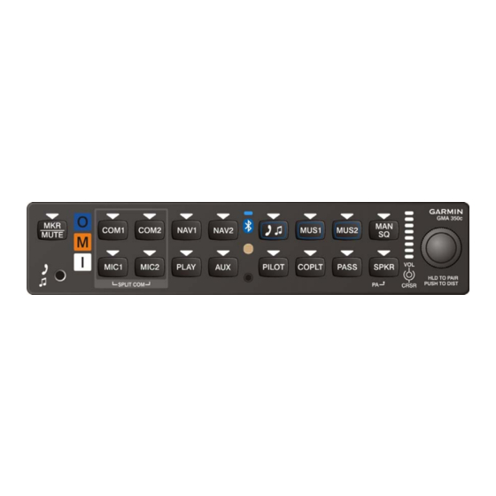
Audio panel
Hide thumbs
Also See for GMA 350:
- Pilot's manual (33 pages) ,
- Installation manual (64 pages) ,
- Pilot's manual (33 pages)

Related Manuals for Garmin GMA 350


Summary of Contents for Garmin GMA 350
- Page 1 GMA 350/350H Installation Manual 190-01134-11 May, 2011 Revision B The document reference is online, please check the correspondence between the online documentation and the printed version.
- Page 2 Garmin. Garmin hereby grants permission to download a single copy of this manual and of any revision to this manual onto a hard drive or other electronic storage medium to be viewed and...
- Page 3 Clarified number of intercom positions and 1.2.1 added 3D Audio 1.3.2 Clarified number of intercom positions Added reference to the GMA 350/350H Configuration Tool User’s Guide Added configuration summary 4.1.1 Edited name of pin 44 Edited name of pin 44...
- Page 4 California’s proposition 65. If you have any questions or would like additional information, please refer site www.garmin.com/prop65. Page ii GMA 350/350H Installation Manual Revision B 190-01134-11 The document reference is online, please check the correspondence between the online documentation and the printed version.
-
Page 5: Table Of Contents
3.3 Antenna Cable Connectors ........................ 3-1 3.4 Electrical Connections ........................3-1 3.5 Backshell Assembly ........................... 3-2 3.6 GMA 350/350H Unit Installation ...................... 3-3 3.7 Post Installation Configuration ......................3-3 3.8 Post Installation Checkout ......................... 3-4 3.8 Continued Airworthiness ........................3-7 SYSTEM INTERCONNECTS ...................... - Page 6 B-4 GMA 350H J3501 Interconnects ...................... B-7 B-5 GMA 350H J3502 Interconnects ...................... B-9 B-6 GMA 350 J3501 & J3502 Connector Layout Drawing ..............B-11 B-7 GMA 350H J3501 & J3502 Connector Layout Drawing ............... B-13 B-8 GMA 350/350H J3501 & J3502 Connector Layout Drawing ............B-15...
- Page 7 PAGE 2-1 Pin and Crimp Tool Part Numbers..................... 2-3 3-1 Pin Contact Part Numbers ........................3-1 3-2 Recommended Crimp Tools ......................3-2 GMA 350/350H Installation Manual Page v 190-01134-11 Revision B The document reference is online, please check the correspondence between the online documentation and the printed version.
- Page 8 The table is current at the time of publication of this manual (see date on front cover) and is subject to change without notice. Authorized Garmin Sales and Service Centers are encouraged to access the most up-to-date bulletin and advisory information on the Garmin Dealer Resource web site at www.garmin.com using their Garmin-provided user name and password.
-
Page 9: General Description
The GMA 350/350H provides a speaker output that may be used as a cockpit speaker or for a PA system to address passengers. The GMA 350/350H also includes a digital recording and playback feature. The GMA 350/350H allows ICS volume adjustments for pilot, copilot, and passenger. - Page 10 Power-off fail safe connection for Pilot PTT, Pilot mic, and Pilot’s Headset-Left to COM 1 *Depends on configuration settings Page 1-2 GMA 350/350H Installation Manual Revision A 190-01134-11 The document reference is online, please check the correspondence between the online documentation and the printed version.
-
Page 11: Technical Specifications
Technical Specifications It is the responsibility of the installing agency to obtain the latest revision of the GMA 350/350H Environmental Qualification Form. This form is available directly from Garmin under the following part number: GMA 350 Environmental Qualification Form, Garmin part number 005-00593-01 To obtain a copy of this form, see the dealer/OEM portion of the Garmin web site (www.garmin.com). - Page 12 VOX processing: individual processing for each mic input ICS auto-squelch/VOX: independent DSP determined thresholds for each mic Entertainment GMA 350 Stereo HiFi music inputs: 3 (two rear connectors and one Functions front panel jack) GMA 350H Stereo HiFi music inputs: 2 (one rear connector and one...
- Page 13 Consumption 1.5 A @ 14 V (maximum) 0.4 A @ 28 V (typical) 1.0 A @ 28 V (maximum) GMA 350/350H Installation Manual Page 1-5 190-01134-11 Revision A The document reference is online, please check the correspondence between the online documentation and the printed version.
-
Page 14: Certification
1.4.2 TSO Deviations Deviation TSO-C35d 1. Garmin was granted a deviation from TSO-C35d to use FAR §21.607(d) instead of FAR §37.7 as the general rules governing holders of the TSO authorizations. 2. Garmin was granted a deviation from TSO-C35d to use RTCA DO-160E instead of RTCA DO-138 as the standard for Environmental Conditions and Test Procedures for Airborne Equipment. -
Page 15: Limited Warranty
Garmin in lieu of repair. Within the applicable period, Garmin will, at its sole option, repair or replace any components that fail in normal use. Such repairs or replacement will be made at no charge to the customer for parts or labor, provided that the customer shall be responsible for any transportation cost. - Page 16 This page intentionally left blank Page 1-8 GMA 350/350H Installation Manual Revision A 190-01134-11 The document reference is online, please check the correspondence between the online documentation and the printed version.
-
Page 17: Installation Overview
AC 43.13-2B, where applicable, may be found useful for making retro-fit installations that comply with FAA regulations. Installation Materials The GMA 350/350H is available as a single unit under the following part number: Item Catalog Part Number GMA 350, Unit Only, (011-02385-00) -
Page 18: Installation Considerations
Installation Considerations The GMA 350/350H interfaces with various avionics equipment. Fabrication of a wiring harness is required. Sound mechanical and electrical methods and practices are required for installation of the GMA 350/350H. 2.3.1 Marker Beacon Antenna Installation 2.3.1.1 Location Considerations The marker beacon antenna should be mounted on a flat surface on the underside of the aircraft body. - Page 19 DANIELS MANUFACTURING CORP 336-00021-00 DMC M22520/2-01 GAGE Garmin Part Number AFM8 CRIMPING TOOL K774 336-00044-00 GMA 350/350H Installation Manual Page 2-3 190-01134-11 Rev. B The document reference is online, please check the correspondence between the online documentation and the printed version.
-
Page 20: Cabling & Wiring
Cooling Air The GMA 350/350H does not have provisions for attaching cooling air and does not generate an excessive amount of heat during typical operations, however the thermal characteristics of the installation should always be assessed. -
Page 21: Mounting Requirements
EMI and provide protection from High-Intensity Radiation Fields (HIRF). The GMA 350/350H is mounted using its own unit rack (Figure 2-2). Refer to Appendix A for installation drawings. The installer must provide any additional remote mounting equipment. -
Page 22: Installation Approval Considerations For Pressurized Aircraft
The wiring diagrams and accompanying notes in this manual should be followed closely to minimize noise effects. Page 2-6 GMA 350/350H Installation Manual Rev. B 190-01134-11 The document reference is online, please check the correspondence between the online documentation and the printed version. -
Page 23: Installation Procedure
If the unit is damaged, notify the carrier and file a claim. To justify a claim, save the original shipping container and all packing materials. Do not return the unit to Garmin until the carrier has authorized the claim. -
Page 24: Backshell Assembly
615725 M81969/1-04 NOTES 1. Non-Garmin part numbers shown are not maintained by Garmin and consequently are subject to change without notice. 2. Extracting the #16, #18 and #20 contact requires that the expanded wire barrel be cut off from the contact. It may also be necessary to push the pin out from the face of the connector when using an extractor due to the absence of the wire. -
Page 25: Gma 350/350H Unit Installation
3. Mount the unit rack to a suitable mounting location on the panel using the provided nutplates. 4. Assemble the rear plate into the GMA 350/350H unit rack. 5. Insert the GMA 350/350H into the rack, noting proper orientation as shown on the installation drawing in Appendix A. -
Page 26: Post Installation Checkout
Post Installation Checkout NOTE The GMA 350/350H does not provide valid outputs until the aircraft post installation configuration procedures are completed. 3.8.1 Verify Failsafe Operation with a Mono Headset 1. Remove power to the unit by pulling the audio breaker. - Page 27 PA to speaker to reliably operate. In these conditions, the “PA to speaker” volume can be set very low and PA audio will still be delivered to the headsets. GMA 350/350H Installation Manual Page 3-5 190-01134-11 Revision B...
- Page 28 Passenger ISO (isolation) toggle key, clearance recorder Play key, PA Mute output, PA Mode Selected output, Com Active output, and Middle Marker Sense output. Page 3-6 GMA 350/350H Installation Manual Revision B 190-01134-11 The document reference is online, please check the correspondence between the online documentation and the printed version.
-
Page 29: Continued Airworthiness
Continued Airworthiness Other than for regulatory periodic functional checks, maintenance of the GMA 350/350H is “on condition” only. GMA 350/350H Installation Manual Page 3-7 190-01134-11 Revision B The document reference is online, please check the correspondence between the online documentation and the printed version. - Page 30 This page intentionally left blank Page 3-8 GMA 350/350H Installation Manual Revision B 190-01134-11 The document reference is online, please check the correspondence between the online documentation and the printed version.
-
Page 31: System Interconnects
TEL MIC OUT LO (GMA 350H Only) ALERT 3 AUDIO IN HI COM 2 MIC KEY* OUT ALERT 1 AUDIO IN HI GMA 350/350H Installation Manual Page 4-1 190-01134-11 Revision B The document reference is online, please check the correspondence between the online documentation and the printed version. - Page 32 ALERT 2,3,4 AUDIO IN LO ALERT 4 AUDIO IN HI * Indicates Active Low Page 4-2 GMA 350/350H Installation Manual Revision B 190-01134-11 The document reference is online, please check the correspondence between the online documentation and the printed version.
- Page 33 PLAY KEY* IN MUSIC 1 IN LEFT MUSIC 1 IN RIGHT MUSIC 1 IN LO RESERVED MUSIC 2 IN LEFT (GMA 350 Only) RESERVED MUSIC 2 IN RIGHT (GMA 350 Only) RESERVED MUSIC 2 IN LO (GMA 350 Only) FAILSAFE WARN AUDIO IN HI...
- Page 34 PASS 4 MIC AUDIO IN LO SPEAKER AUDIO OUT LO SPEAKER AUDIO OUT HI * Indicates Active Low Page 4-4 GMA 350/350H Installation Manual Revision B 190-01134-11 The document reference is online, please check the correspondence between the online documentation and the printed version.
-
Page 35: Power
4.4 Lighting Pin Name Connector LIGHTING BUS IN HI P3502 LIGHTING BUS IN LO P3502 GMA 350/350H Installation Manual Page 4-5 190-01134-11 Revision B The document reference is online, please check the correspondence between the online documentation and the printed version. -
Page 36: Audio Inputs And Outputs
TEL AUDIO IN HI P3501 TEL AUDIO IN LO P3501 TEL MIC OUT HI P3501 TEL MIC OUT LO P3501 4.5.5 Telephone (GMA 350) Pin Name Connector TEL AUDIO IN HI P3501 TEL AUDIO LO P3501 TEL AUDIO OUT HI... - Page 37 4.5.9 Speaker Outputs Pin Name Connector SPEAKER AUDIO OUT LO P3502 SPEAKER AUDIO OUT HI P3502 GMA 350/350H Installation Manual Page 4-7 190-01134-11 Revision B The document reference is online, please check the correspondence between the online documentation and the printed version.
-
Page 38: Music Inputs
MUSIC 1 IN LEFT P3502 MUSIC 1 IN RIGHT P3502 MUSIC 1 IN LO P3502 MUSIC 2 IN LEFT (GMA 350 Only) P3502 MUSIC 2 IN RIGHT (GMA 350 Only) P3502 MUSIC 2 IN LO (GMA 350 Only) P3502 4.7 Mic Keys... - Page 39 APPENDIX A OUTLINE AND INSTALLATION DRAWINGS Figure A-1. GMA 350/350H Outline Drawing GMA 350/350H Installation Manual Page A-1 (Page A-2 blank) 190-01134-11 Rev B The document reference is online, please check the correspondence between the online documentation and the printed version.
- Page 40 APPENDIX A OUTLINE AND INSTALLATION DRAWINGS Figure A-2. GMA 350/350H Connector/Rack Assembly Drawing GMA 350/350H Installation Manual Page A-3 (Page A-4 blank) 190-01134-11 Rev B The document reference is online, please check the correspondence between the online documentation and the printed version.
- Page 41 APPENDIX A OUTLINE AND INSTALLATION DRAWINGS Figure A-3. Recommended Panel Cutout Drawings GMA 350/350H Installation Manual Page A-5 (Page A-6 blank) 190-01134-11 Rev B The document reference is online, please check the correspondence between the online documentation and the printed version.
- Page 42 APPENDIX B INTERCONNECT DRAWINGS Figure B-1. Notes GMA 350/350H Installation Manual Page B-1 (Page B-2 blank) 190-01134-11 Rev B The document reference is online, please check the correspondence between the online documentation and the printed version.
- Page 43 APPENDIX B INTERCONNECT DRAWINGS GMA 350 Interconnects (refer to B-4 and B-5 for GMA 350H interconnects) Figure B-2. GMA 350 J3501 Interconnects GMA 350/350H Installation Manual Page B-3 (Page B-4 blank) 190-01134-11 Rev B The document reference is online, please check the correspondence between the online documentation and the printed version.
- Page 44 APPENDIX B INTERCONNECT DRAWINGS GMA 350 Interconnects (refer to B-4 and B-5 for GMA 350H interconnects) Figure B-3. GMA 350 J3502 Interconnects GMA 350/350H Installation Manual Page B-5 (Page B-6 blank) 190-01134-11 Rev B The document reference is online, please check the correspondence between the online documentation and the printed version.
- Page 45 APPENDIX B INTERCONNECT DRAWINGS GMA 350H Interconnects (refer to B-2 and B-3 for GMA 350 interconnects) Figure B-4. GMA 350H J3501 Interconnects GMA 350/350H Installation Manual Page B-7 (Page B-8 blank) 190-01134-11 Rev B The document reference is online, please check the correspondence between the online documentation and the printed version.
- Page 46 APPENDIX B INTERCONNECT DRAWINGS GMA 350H Interconnects (refer to B-2 and B-3 for GMA 350 interconnects) Figure B-5. GMA 350H J3502 Interconnects GMA 350/350H Installation Manual Page B-9 (Page B-10 blank) 190-01134-11 Rev B The document reference is online, please check the correspondence between the online documentation and the printed version.
- Page 47 APPENDIX B INTERCONNECT DRAWINGS Figure B-6. GMA 350 J3501 & J3502 Connector Layout Drawing GMA 350/350H Installation Manual Page B-11 (Page B-12 blank) 190-01134-11 Rev B The document reference is online, please check the correspondence between the online documentation and the printed version.
- Page 48 APPENDIX B INTERCONNECT DRAWINGS Figure B-7. GMA 350H J3501 & J3502 Connector Layout Drawing GMA 350/350H Installation Manual Page B-13 (Page B-14 blank) 190-01134-11 Rev B The document reference is online, please check the correspondence between the online documentation and the printed version.
- Page 49 APPENDIX B INTERCONNECT DRAWINGS Figure B-8. GMA 350/350H J3501 & J3502 Connector Layout Drawing GMA 350/350H Installation Manual Page B-15 (Page B-16 blank) 190-01134-11 Rev B The document reference is online, please check the correspondence between the online documentation and the printed version.
- Page 50 The document reference is online, please check the correspondence between the online documentation and the printed version.
Need help?
Do you have a question about the GMA 350 and is the answer not in the manual?
Questions and answers