Garmin Volvo Penta GLASS COCKPIT 8x10 Owner's Manual
Hide thumbs
Also See for Volvo Penta GLASS COCKPIT 8x10:
- Installation instructions manual (8 pages) ,
- Installation instructions manual (27 pages)
Table of Contents
Advertisement
Quick Links
Advertisement
Table of Contents

Related Manuals for Garmin Volvo Penta GLASS COCKPIT 8x10


Summary of Contents for Garmin Volvo Penta GLASS COCKPIT 8x10
- Page 1 Owners manual VOLVO PENTA GLASS COCKPIT...
- Page 2 © 2019 Garmin Ltd. or its subsidiaries All rights reserved. Under the copyright laws, this manual may not be copied, in whole or in part, without the written consent of Garmin. Garmin reserves the right to change or improve its products and to make changes in the content of this manual without obligation to notify any person or organization of such changes or improvements.
-
Page 3: Table Of Contents
Table of Contents Voice Control..........7 Enabling Voice Control......8 Supported Headsets....... 8 Introduction...........1 Pairing a Wireless Headset with a Garmin Device Overview........1 Chartplotter..........8 Status Icons..........1 Using a Wireless Headset with a Garmin Using the Touchscreen......1 Chartplotter.......... - Page 4 Community with Garmin Connect..24 Adjusting the Wind Sensor Orientation..........13 Garmin Quickdraw Contours Settings..24 Viewing Boat Data on a Garmin Watch..13 Navigation with a Chartplotter..25 Viewing Boat Data on a Garmin Nautix™ Device............14 Basic Navigation Questions..... 25 Route Color Coding........
- Page 5 Split-Frequency Sonar View....37 Boundaries..........32 Split-Zoom Sonar View......37 Creating a Boundary......32 Garmin ClearVü Sonar View....37 Converting a Route to a Boundary..32 Garmin SideVü Sonar View......37 Converting a Track to a Boundary..32 SideVü Scanning Technology....38 Editing a Boundary.......
- Page 6 Zooming in a Panoptix LiveVü or LiveScope MotionScope™ Doppler Sonar View..........41 Radar Technology........51 Adjusting the Level of Detail..... 41 Enabling a Guard Zone......51 Adjusting the Color Intensity.....41 Defining a Circular Guard Zone.... 51 Sonar Setup..........42 Defining a Partial Guard Zone....51 Setting the Zoom Level on the Sonar MARPA.............51 Screen..........
- Page 7 Cancelling a Steering Pattern....58 Individual Routine Calls......62 Adjusting the Autopilot Response.... 58 Selecting a DSC Channel..... 62 Enabling the Autopilot Controls on a Garmin Making an Individual Routine Call..62 Watch............58 Making an Individual Routine Call to an Customizing the Autopilot Button AIS Target..........63...
- Page 8 Adding and Editing a Digital Switching Page............66 Scanning VHF Channels...... 70 Garmin Boat Switch™......66 Adjusting the VHF Squelch....70 Configuring the Garmin Boat Switch Radio............70 Device........... 66 Setting the Tuner Region...... 70 Using the Bilge Pump Switches.... 67 Changing the Radio Station....
- Page 9 Chartplotter........78 Settings..........87 Adding the VIRB Action Camera Controls Other Vessels Settings......87 to Other Screens........79 Settings that are Synced on the Garmin HDMI Video Considerations..... 79 Marine Network........87 Controlling HDMI Audio......79 Restoring the Original Chartplotter Factory Pairing the GC™...
- Page 10 Saving System Information to a Memory Card............89 Appendix..........89 ActiveCaptain and Garmin Express..89 Garmin Express App........ 90 Installing the Garmin Express App on a Computer..........90 Registering Your Device Using the Garmin Express App......90 Updating Your Charts Using the Garmin Express App.........
-
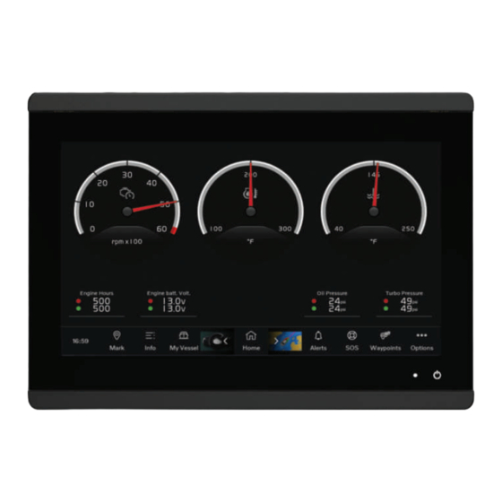
Page 11: Introduction
Using the Touchscreen product. • Tap the screen to select an item. The Volvo Penta Glass Cockpit, designed in a collaboration between Volvo Penta and Garmin ® , has • Drag or swipe your finger across the screen to pan or a new user interface that includes instrumentation for scroll. -
Page 12: Locking And Unlocking The Touchscreen
• Select Options to open additional settings about that accessing regulatory information. screen. 1 Go to garmin.com/manuals/VolvoGlassCockpit8600. • Select Toolbars to quickly add an overlay to the current page. 2 Download the manual. -
Page 13: Inserting Memory Cards (8X10/8X12/8X16)
The features are connect a memory card reader or a chartplotter model dependent on the accessories you have connected to with a built-in memory card slot to the Garmin Marine the chartplotter. You may not have all of the options and Network. -
Page 14: Pinning A Feature Button
When multiple displays are installed on the Garmin Marine Opens the Alert Manager, which shows the Volvo Network, you can group them together into a station. A Penta alerts, vessel alerts, and navigation alerts station enables the displays to work together, instead TIP: The icon changes color to indicate severity. -
Page 15: Hiding And Showing The Menu Bar
Hiding and Showing the Menu Bar Display resolution Image width Image height You can hide the menu bar automatically to make more screen space available. WVGA 1 Select Options > Settings > Preferences > Menu Bar WSVGA Display > Auto. After a short period of time on a main page, such as a WXGA 1080... -
Page 16: Adding A Smartmode Layout
Adding a SmartMode Layout 3 Select Edit Layout or Edit Combo. You can add SmartMode layouts to suit your needs. Each 4 Select an option: customization made to one SmartMode layout in a station • To change the name, select Name or Name & appears on all displays in the station. -
Page 17: Linking A Layout To The Control And Joystick Buttons
4 Select a layout to link to the item or button. Voice Control 5 If necessary, repeat steps 2–4 for the remaining After installing the Garmin Voice Control USB module buttons. (010-13194-00), you can use your voice to control the When you press the assigned button on the control or chartplotter using a compatible headset. -
Page 18: Enabling Voice Control
(other Show Clear View sonar screen than OK Garmin). You can try saying variations of these commands in a way that is natural to you. An expanded Opens the Garmin SideVü... -
Page 19: Grid Remote Control
Pairing the GRID Device with the Chartplotter from the software, and plan your trip. You can also control the Chartplotter GLASS COCKPIT device from the app using the Garmin NOTE: These steps are applicable to both the GRID Helm feature. -
Page 20: Getting Started With The Activecaptain App
Clear. 8 From your mobile device settings, open the Wi‑Fi ® Managing Notifications connections page and connect to the Garmin device, using the name and password you entered in the WARNING Garmin device. Do not read or reply to notifications while operating the vessel. -
Page 21: Making Notifications Private
• To turn off pop-up notifications on this chartplotter, a memory card (Updating Your Charts Using the select Popups. Garmin Express App, page 90). The Garmin Express • To turn off pop-up notifications and disable access app downloads large charts more quickly than the to the messages list on this chartplotter, select ActiveCaptain app. -
Page 22: Purchasing A Chart Subscription With Activecaptain
Garmin Express desktop app. You can 3 Select the map to update. download updated charts and content each day. 4 Select the area to download. You can purchase chart subscriptions in a variety of ways. 5 Select Download. -
Page 23: Changing The Wireless Channel
You can connect a compatible Garmin watch to a Remote. compatible chartplotter to view data from the chartplotter. 2 Select New Connection. 1 Bring the Garmin watch within range (3 m) of the 3 Follow the on-screen instructions. chartplotter. Turning On and Off the Remote Backlight 2 From the watch clock screen, select START >... -
Page 24: Viewing Boat Data On A Garmin Nautix Device
Relief Shading: Provides high resolution elevation vessels. shading of lakes and coastal waters. This chart can be 1 Bring the a Garmin Nautix device within range (3 m) of helpful for fishing and diving. the chartplotter. NOTE: The Relief Shading chart is available with The device automatically looks for all compatible premium charts, in some areas. -
Page 25: Zooming In And Out Using The Touchscreen
Navigating to a Point on the Chart Icon Description WARNING Overhead photo available All route and navigation lines displayed on the chartplotter are only intended to provide general route guidance or to identify proper channels, and are not intended Perspective photo available to be precisely followed. -
Page 26: Fish Eye 3D Chart View
Using the depth contour lines of the premium charts, such pointing upward indicates a rising tide. When you move as Garmin Navionics Vision+, the Fish Eye 3D chart view the cursor over the tide station indicator, the height of the provides an underwater view of the sea floor or lake tide at the station appears above the station indicator. -
Page 27: Showing Satellite Imagery On The Navigation Chart
Automatic Identification System Showing Tides and Current Indicators NOTE: This feature is available with premium charts, in The Automatic Identification System (AIS) enables you some areas. to identify and track other vessels, and alerts you to area traffic. When connected to an external AIS device, You can show static or animated tide and current station the chartplotter can show some AIS information about indicators on the Navigation chart or Fishing chart. -
Page 28: Heading And Projected Course Of Activated Ais Targets
Viewing Information about a Targeted AIS Vessel Symbol Description You can view the AIS signal status, MMSI, GPS speed, GPS heading, and other information that is reported about Dangerous target is lost. A red X indicates a targeted AIS vessel. that the AIS transmission from the vessel is lost, and the chartplotter displays a message 1 From a chart or a 3D chart view, select an AIS vessel. -
Page 29: Viewing A List Of Ais And Marpa Threats
3 Select Time To, and select a time at which the alarm Symbol Meaning will sound if a target is determined to intersect the safe zone. Real or synthetic ATON: Topmark Safe For example, to be notified of a pending intersection 10 minutes before it will likely occur, set Time To to 10, Real or synthetic ATON: Topmark Danger and the alarm will sound 10 minutes before the vessel... -
Page 30: Turning Off Ais Reception
(Water Layer • To receive or ignore Search and Rescue Settings, page 21). Transponder (SART) test signals, select AIS-SART Test. Quickdraw Contours: Shows and hides Garmin Quickdraw Contours data (Garmin Quickdraw Contours Turning Off AIS Reception Settings, page 24). AIS signal reception is turned on by default. - Page 31 The depth ranges apply to all charts and all bodies the list of boundaries. of water. Tracks: Shows tracks on the chart. Some Garmin LakeVü and premium supplemental charts ™ have multiple depth range shading by default. Other Vessels Layer Settings NOTE: These options require connected accessories, such as an AIS receiver, radar, or VHF radio.
-
Page 32: Chart Settings
Garmin or an approved third party producer. the radar view (Other Vessels Layer Settings, page 21). You can purchase maps from Garmin. If you purchase Radar Setup: Opens the radar display settings (Radar maps from a seller other than Garmin, investigate the Setup Menu, page 55). -
Page 33: Mapping A Body Of Water Using The Garmin Quickdraw Contours Feature
When you record data on a memory card in your Contours. chartplotter, the new data is added to your existing Garmin Quickdraw Contours map, and is saved on the memory 2 Use the map and search features to locate an area to card. -
Page 34: Connecting To The Garmin Quickdraw Community With Garmin Connect
2 Select Getting Started > Quickdraw Community > 5 Select Select an Area to Download. Getting Started. 6 Drag the edges of the box to select the area to 3 If you do not have a Garmin Connect account, create download. one. 7 Select Start Download. -
Page 35: Navigation With A Chartplotter
Depth Shading: Specifies the minimum and maximum NOTE: Auto Guidance is available with premium depths of a depth range and a color for that depth charts, in some areas. range. The color of the route line changes depending upon several factors (Route Color Coding, page 25). -
Page 36: Destinations
1 Select a destination (Destinations, page 26). in shallow waters. This line is red striped in Garmin Navionics+ and Garmin Navionics Vision+ charts only; 2 Select Navigate To > Go To. it is magenta and gray striped in previous versions of A magenta line appears. -
Page 37: Creating A Waypoint At A Different Location
Creating a Waypoint at a Different Location Moving a Saved Waypoint 1 Select Waypoints > New Waypoint. 1 Select Info > User Data > Waypoints. 2 Select an option: 2 Select a waypoint. • To create the waypoint by entering position 3 Select Review >... -
Page 38: Deleting A Waypoint Or An Mob
5 Review the course indicated by the magenta line. Viewing a List of Routes and Auto Guidance Paths 1 Select Info > User Data > Routes. NOTE: When using Auto Guidance, a gray segment within any part of the magenta line indicates that Auto 2 If necessary, select Filter to see routes only or Auto Guidance cannot calculate part of the Auto Guidance Guidance paths only. -
Page 39: Browsing For And Navigating Parallel To A Saved Route
Browsing for and Navigating Parallel to a Saved Route 3 Enter the search parameters. Before you can browse a list of routes and navigate to 4 Select Done. one of them, you must create and save at least one route 5 If necessary, select Engage. -
Page 40: Adjusting A Saved Auto Guidance Path
Guidance path appears as a solid orange line or a red • If the line is too close to known obstacles, select striped line in Garmin Navionics+ and Garmin Navionics Options > Settings > Preferences > Navigation > Vision+ charts and appears as a magenta and gray Auto Guidance >... -
Page 41: Tracks
7 If you selected Near or Far in step 6, review the Saving the Active Track placement of the Auto Guidance line, and determine The track currently being recorded is called the active whether the line safely avoids known obstacles and the track. -
Page 42: Retracing The Active Track
Retracing the Active Track Boundaries allow you to avoid or remain in designated The track currently being recorded is called the active areas in a body of water. You can set an alarm to alert you track. when you enter or exit a boundary. 1 Select Info >... -
Page 43: Disabling All Boundary Alarms
3 Select Review > Alarm. When the end point is past the start line, the line is red. This indicates the boat must reduce speed to avoid a 4 Select an option: penalty for reaching the start line before the timer expires. •... -
Page 44: Laylines Settings
To use the laylines features, you must connect a wind sensor to the chartplotter. 1 Save the polar table file (polar.plr) to the Garmin/ polars/ folder on the memory card. When in sailing mode (Setting the Vessel Type, page you can display laylines on the navigation chart. -
Page 45: Setting The Keel Offset
TIP: You can also use the polar table data when Setting the Heading Line and Angle Markers calculating laylines and starting line guidance. The heading line is an extension drawn on the map from the bow of the boat in the direction of travel. Angle Setting the Keel Offset markers indicate relative position from the heading or You can enter a keel offset to compensate the water... -
Page 46: Creating A Water Sports User Preset
For more information about which transducer is best for You can, fill, drain, or adjust the amount of water in your your needs, go to garmin.com/transducers. ballast tanks to create a larger or smaller wake for water Different sonar views can help you view the fish in the area. -
Page 47: Stopping The Transmission Of Sonar Signals
For example, you can view certain Panoptix ™ NOTE: To receive Garmin ClearVü scanning sonar, you sonar screens only if you have a compatible Panoptix need a compatible transducer. For information about transducer connected. -
Page 48: Sidevü Scanning Technology
The RealVü 3D sonar views provide three-dimensional The transducer on your vessel views of either what is in front of or below your boat. The screen updates with each sweep of the transducer. Logs To see all five Panoptix sonar views, you need one transducer to show the down views and a second transducer to show the forward views. -
Page 49: Realvü 3D Forward Sonar View
Trails Fish Bottom Bottom RealVü 3D Forward Sonar View RealVü 3D Historical Sonar View This sonar view shows a three-dimensional view of what is This sonar view provides a three-dimensional view of what in front of the transducer. This view can be used when you is behind your boat as you are moving and shows the are stationary and you need to see the bottom and the fish entire water column in 3D, from the bottom to the top of... -
Page 50: Livescope Sonar View
For example, if you have two sources for Garmin ClearVü, you can select the source to use from the Garmin ClearVü sonar view. 1 Open the sonar view for which you will change the source. -
Page 51: Pausing The Sonar Display
2 Select Back to exit history. Sonar Sharing You can view the sonar data from all compatible sources on the Garmin Marine Network. You can view sonar data from a compatible external sonar module, such as a ™ sonar module. In addition, you can view the sonar... -
Page 52: Sonar Setup
1 From a sonar view, select Options. 2 Select an option: 2 Select an option: • To set the depth and zoom automatically, select • While in the Garmin ClearVü/SideVü sonar view, Auto. select Contrast. If necessary, select Set Zoom to modify the zoom •... -
Page 53: Adjusting The Range
You can adjust the range of the depth scale for traditional to control and suppress clutter or noise near the water and Garmin ClearVü sonar views. You can adjust the surface. It also allows for the display of targets near the range of the width scale for the SideVü... -
Page 54: Sonar Alarms
You can also open the sonar alarms by selecting Options Setup > Installation. > Settings > Alarms > Sonar. • From a Garmin ClearVü sonar view, select Options > Shallow Water: Sets an alarm to sound when the depth is ClearVü Setup > Installation. -
Page 55: Sonar Frequencies
target edges and may also reduce noise. This option is You can select which frequencies appear on the sonar available on the Traditional sonar view only. screen. Flip Left/Right: Switches the SideVü view orientation NOTICE from left to right. This option is available on the SideVü Always be aware of local regulations on sonar sonar view only. -
Page 56: Panoptix Sonar Setup
Panoptix Sonar Setup the effectiveness of the FrontVü Alarm, reducing your reaction time to low depth readings. Adjusting the RealVü Viewing Angle and Zoom Level Transmit Angle: Adjusts the focus of the transducer to You can change the viewing angle of the RealVü sonar the port or starboard side. -
Page 57: Realvü Appearance Settings
offset when using the front collision alarm (Setting the Bottom Style: Sets the style for the bottom. When you Bow Offset, page 48). are in deep water, you can select the Points option and manually set the range to a shallower value. 1 From the FrontVü... -
Page 58: Livescope And Perspective Sonar Settings
Setting the Bow Offset If you want to see the highest intensity signal returns For forward view Panoptix transducers, you can enter a on the screen, you can lower the gain to remove bow offset to compensate the forward distance readings lower intensity returns and noise. -
Page 59: Livescope And Perspective Appearance Settings
Panoptix transducers are connected. When you connect your compatible chartplotter to an optional Garmin marine radar, such as a GMR ™ Fantom ™ On-screen Control: Shows the on-screen buttons. -
Page 60: Radar Interpretation
> Timed Transmit. Radar Overlay 2 Select Timed Transmit to enable the option. When you connect your chartplotter to an optional Garmin 3 Select Stdby Time, enter the time interval between marine radar, you can use overlay radar information on radar signal transmissions, and select Done. -
Page 61: Adjusting The Radar Range
Adjusting the Radar Range The range of the radar signal indicates the length of the pulsed signal transmitted and received by the radar. As the range increases, the radar transmits longer pulses in order to reach distant targets. Closer targets, especially rain and waves, also reflect the longer pulses, which can add noise to the Radar screen. -
Page 62: Marpa Targeting Symbols
Assigning a MARPA Tag to an Object Mini-automatic radar plotting aid (MARPA) enables you to identify and track targets and is primarily used for collision Before you can use MARPA, you must have a heading avoidance. To use MARPA, you assign a MARPA tag sensor connected and an active GPS signal. -
Page 63: Echo Trails
Clearing the Echo Trails your boat to a target object. On the Radar screen, the VRM appears as a circle that is centered on the present You can remove the echo trails from the radar screen to location of your boat, and the EBL appears as a line that reduce the clutter on the screen. -
Page 64: Radar Filter Settings
Minimizing Nearby Large-Object Interference When using a compatible radar model, the chartplotter Nearby targets of significant size, such as jetty walls, can adjusts the sea clutter based on the sea conditions cause a very bright image of the target to appear on the automatically. -
Page 65: Radar Setup Menu
Radar Installation Settings VRM/EBL: Shows the variable range marker (VRM) circle and the electronic bearing line (EBL) to allow you to Front of Boat: Compensates for the physical location of measure the distance and bearing from your boat to a the radar when it is not on the boat axis (Measuring and target object... -
Page 66: Autopilot
The system also allows manual steering and several modes of automatic-steering functions and patterns. When the chartplotter is connected to a compatible Garmin autopilot system, you can engage and control the autopilot from the chartplotter. For information about compatible Garmin autopilot systems, go to garmin.com. -
Page 67: Enabling Shadow Drive
Enabling Shadow Drive Adjusting the Heading with the Chartplotter in Step Steering Mode From the autopilot screen, select Options > Autopilot 1 Engage a heading hold (Engaging the Autopilot, Setup > Shadow Drive > Enabled. page 57). Autopilot Overlay Bar 2 Select an option: NOTE: Not all options are available on all autopilot •... - Page 68 Enabling the Autopilot Controls on a Garmin 1 From the autopilot screen, select Options > Pattern Watch Steering > Orbit. You can control the Garmin autopilot with a compatible 2 Select Engage Port or Engage Starboard. Garmin watch. Go to garmin.com...
- Page 69 1 Insert a memory card into the card slot on the You can connect the chartplotter wirelessly to a computer. compatible Garmin Force trolling motor on your boat to control the trolling motor from the chartplotter. 2 Go to garmin.com/software/autopilot_remote_control, and select Software.
- Page 70 Adding the Trolling Motor Controls to Enables heading hold (set and maintain the Screens current heading). After you have connected the chartplotter to the Force When the trolling motor is in heading hold, an trolling motor, you must add the trolling motor control bar autopilot bar appears in the trolling motor bar.
- Page 71 • The chartplotter can track the positions of vessels 4 Select Go To or Route To. sending position reports. If you have a Garmin NMEA 2000 VHF radio connected to your chartplotter, these features are also enabled. Digital Selective Calling...
- Page 72 Man-Overboard and SOS Distress Calls Initiated from the Chartplotter 2 Select a position-report call. When your chartplotter is connected to a Garmin NMEA 3 Select Review > Edit > Clear Report. 2000 compatible radio and you mark an SOS or man-...
- Page 73 4 Select a data type. radio. 5 Select the data to display. 6 On your Garmin VHF radio, complete the call. Customizing the Gauges Making an Individual Routine Call to an AIS Target You can add a gauge page, change the layout of the 1 From a chart or 3D chart view, select an AIS target.
- Page 74 Viewing Graphs 3 Select Name, enter a name, and select Done. Before you can view graphs of various environmental 4 Select Type, and select the type of sensor. changes, such as temperature, depth, and wind, you must 5 Select Style, and select the style of sensor. have an appropriate transducer or sensor connected to 6 Select Tank Capacity, enter the capacity of the tank, the network.
-
Page 75: Connecting An Inreach Device To The Chartplotter
Sending an inReach Preset Message EVC network, such as features, components, software Preset messages are messages that you created at versions, and calibration. explore.garmin.com. Preset messages have predefined From the menu bar, select My Vessel > Status > EVC text and recipients. Network. -
Page 76: Digital Switching
NMEA 2000 network as the Garmin Boat Switch Garmin Boat Switch device to use the wiring option you device, select Options > Settings > My Vessel > that applies to your installation type. -
Page 77: Using The Bilge Pump Switches
67). You can manually operate connected bilge pumps by using switches 12 and 13 on the Garmin chartplotter. 1 From a Garmin chartplotter connected to the same NMEA 2000 network as the Garmin Boat Switch device, select Vessel > Switching. -
Page 78: Tide, Current, And Celestial Information
Viewing Tide Station, Current Station, or You are responsible for the safe and prudent operation of your vessel. Use of Limp Home mode does not relieve you Celestial Information for a Different Date of the responsibility of safely operating your boat. Avoid 1 Select Info >... -
Page 79: Saving Messages To A Memory Card
™ compatible stereo connected You can browse for music in some media sources. to the NMEA 2000 network or Garmin Marine Network, 1 From the media screen and an applicable source, you can control the stereo using the chartplotter. The select Browse. -
Page 80: Adjusting The Volume
Adjusting the Volume NOTE: Not all tuning modes are available for all media sources. Muting the Media Volume 1 From the media screen, select Options > Tuning 1 From the media screen, select Mode. 2 If necessary, select Select. 2 Select an option. Enabling and Disabling Zones 3 If necessary, select Select. -
Page 81: Scanning For Dab Stations
SiriusXM Satellite Radio Scanning for DAB Stations NOTE: Because DAB signals are broadcast in select When you have a FUSION-Link ™ capable stereo and countries only, you must set the tuner region to a location SiriusXM Connect Tuner installed and connected to the where DAB signals are broadcast. -
Page 82: Parental Controls
This process deletes all the settings information you have Garmin will not be responsible for any consequences of entered. When you restore the parental control settings to using SiriusXM weather information. -
Page 83: Weather Data Broadcasts
Weather data is broadcast at different intervals for each weather feature. For example, radar is broadcast at five- Hurricane Information minute intervals. When the Garmin receiver is turned The weather Precipitation chart can show the present on, or when a different weather feature is selected, the... -
Page 84: City Forecasts
Viewing Sea Conditions Pressure- The Sea Conditions feature shows information about Center Description surface conditions, including winds, wave height, wave Symbol period, and wave direction. Indicates a low-pressure center, which Select Charts > Sea Conditions. is a region of relatively lower pressure. Surface Winds Moving away from a low-pressure center Surface wind vectors appear on the Sea Conditions chart... -
Page 85: Viewing Sea Temperature Information
Compatible devices include video devices connected to in 12-hour increments, select multiple times. the ports on the chartplotter or to the Garmin Marine • To view the visibility forecast for the previous 36 Network, as well as supported network (IP-based) video... -
Page 86: Selecting A Video Source
You can connect multiple supported video cameras and Change Scene: Selects the infrared image mode, such as up to two video encoders to the Garmin Marine Network. day, night, MOB, or docking. You can select and view up to four video sources at Video Setup: Opens more video options. -
Page 87: Associating The Camera To A Video Source
Do not aim the camera at the sun or extremely bright source format, select Standard > Auto. objects. Damage to the lens may occur. Always use the chartplotter controls or buttons to pan and Garmin VIRB Action Cameras ® tilt the camera. Do not manually move the camera unit. -
Page 88: Connecting A Virb Action Camera
Connecting a VIRB Action Camera To view the high-resolution video, view the video on a You connect a VIRB action camera to the chartplotter computer or television. using the camera settings. If you are connecting a VIRB 1 From the VIRB® screen, select 360 camera, connect through the VIRB app (Connecting a 2 Wait a few seconds for the thumbnail images to load. -
Page 89: Adding The Virb Action Camera Controls To Other Screens
Video Timestamp: Adds the date and time a video was connect the two HDMI cables. recorded. You need a Garmin GPSMAP USB OTG adapter cable to Photo Timestamp: Adds the date and time a photo was power a media player stick. The USB port can supply up taken. -
Page 90: Pairing The Gc™ 100 Camera With A Garmin Chartplotter
2 On the chartplotter, select Options > Settings > By default, two individual camera Communications > Wireless Devices > Garmin feeds are shown on the surround Camera > Start. view screen. You can customize this to show only one camera 3 Follow the on-screen instructions. -
Page 91: Showing And Hiding The Visual Bumper
Showing and Hiding the Visual Bumper Backlight: Sets the backlight brightness. You can select the Auto option to adjust the backlight brightness The visual bumper is an adjustable perimeter line you can automatically based on the ambient light. set around your boat. The visual bumper appears on the birds-eye view only, and can help you judge how close Color Mode: Sets the device to display day or night objects are to your boat. -
Page 92: Station Settings
You can view the software version, the basemap time. version, all supplemental map information (if applicable), Navigation Settings the software version for an optional Garmin radar (if NOTE: Some settings and options require additional applicable), and the unit ID number. You may need this charts or hardware. -
Page 93: Communications Settings
NOTE: Auto Guidance is available with premium charts, in 6 Select an option: some areas. • If the placement of the line is satisfactory, select NOTE: Not all settings apply to all maps. Options > Navigation Options > Stop Navigation, and proceed to step 10. -
Page 94: Marine Network
3 Select Set Radius, and select a distance on the chart. You can name devices and sensors connected to the 4 Select Back. Garmin Marine Network and the NMEA 2000 network. System Alarms 1 Select Options > Settings > Communications. -
Page 95: Setting The Fuel Alarm
such as a GXM device, and have a valid weather Toe Angle: The setting should be changed by authorized subscription. Volvo Penta personnel only. 1 Select Options > Settings > Alarms > Weather. Speed Factor: Calibrates the displayed boat speed. 2 Turn on alarms for specific weather events. -
Page 96: Setting The Water Temperature Offset
NOTE: This option is only available when you have valid 4 Complete an action: depth data. • If the sensor or transducer is connected to the 1 Measure the distance: chartplotter or a sonar module, select Options > Settings > My Vessel > Temp. Offset. •... -
Page 97: Fuel Tank Settings
GPSMAP chartplotters sync ™ Trim Zero Set: Allows you to initialize the trim angle to certain settings when connected to the Garmin Marine zero when all motors are fully trimmed down. Network. Tank Preset: Sets the tank name, fluid type, sensor... -
Page 98: Restoring The Original Chartplotter Factory Settings
User data includes waypoints, saved tracks, routes, and • Calibrate Water Speed boundaries. • Radar Antenna Size • You can share data across the Garmin Marine Network. Chart Settings: • You can share and manage user data using a memory • Chart Borders card. -
Page 99: And Garmin Express
(Garmin Express App, page 90). You should File. use the Garmin Express app for faster data transfer of 4 Select Save to Card. larger downloads and updates, and to avoid possible 5 Remove the memory card, and insert it into a card data charges with some mobile devices. -
Page 100: Garmin Express App
When you add devices to the chartplotter network, repeat these steps to register the new devices using the Garmin Receive smart notification on Express app. the chartplotter Updating Your Charts Using the Garmin Express App... -
Page 101: Software Updates
5 Read and agree to the terms. ActiveCaptain App, page 11). 6 Select the drive for the memory card. You can also use the Garmin Express desktop app 7 Review the reformat warning, and select Continue. to update your chartplotter software (Loading the New... -
Page 102: Controlling A Computer With The Chartplotter
Controlling a Computer with the Chartplotter computer. Before you can control a computer using the chartplotter, 2 From Windows Explorer, open the Garmin\scrn folder you must connect the chartplotter and computer correctly. on the memory card. See the chartplotter installation instructions for connection 3 Copy the image file from the card and paste it to any information. -
Page 103: My Device Will Not Turn On Or Keeps Turning Off
GPS signal. Contacting Volvo Penta Support My device will not turn on or keeps turning off • Go to support.garmin.com for help and information, Devices erratically turning off or not turning on could such as product manuals, frequently asked questions, indicate an issue with the power supplied to the device. -
Page 104: Glass Cockpit 8X12 Specifications
Water rating to 1 m for up to 30 min. For Polycarbonate plastic and die-cast more information, go to Material aluminum .garmin.com/waterrating. IEC 60529 IPX7 Fuse 10 A, 125 V fast-acting The device withstands incidental Input voltage From 10 to 32 Vdc... -
Page 105: Glass Cockpit 8X17 Specifications
1 m Water rating Water rating for up to 30 min. For more infor- for up to 30 min. For more infor- mation, go to www.garmin.com mation, go to www.garmin.com /waterrating. /waterrating. Fuse 15 A... -
Page 106: Glass Cockpit 8X24 Specifications
The device withstands incidental exposure to water of up to 1 m Water rating 127258 Magnetic variance for up to 30 min. For more infor- mation, go to www.garmin.com 127488 Engine parameters: Rapid update /waterrating. 127489 Engine parameters: Dynamic Fuse 15 A... -
Page 107: Nmea 0183 Information
Description Description 127505 Fluid level 129802 AIS safety-related broadcast message 130060 Label 129808 DSC call Information 129809 AIS class B "CS" static data report, part A Transmit 129810 AIS class B "CS" static data report, part B Description 130313 Humidity 126464 Transmit and receive PGN list group function 130314 Actual pressure 126984 Alert Response... -
Page 108: Engine Information Transmitted Over The Updating Built-In Maps With A Memory Card Nmea 2000 Bridge
Receive EVC Data Received NMEA 2000 Output PGN Sentence Description Transmission oil pressure* Transmission oil tempera- 127493: Transmission Depth ture* parameters, dynamic Depth below transducer Transmission gear Water temperature Fluid level: Fuel* 127505: Fluid level Fluid level: Fresh water* Water speed and heading Rudder position* 127245: Rudder Waypoint location... - Page 110 AB Volvo Penta SE-405 08 Göteborg, Sweden March 2022 Printed in the UK 190-01977-10_0L...
Need help?
Do you have a question about the Volvo Penta GLASS COCKPIT 8x10 and is the answer not in the manual?
Questions and answers