Advertisement
Available languages
Available languages
Quick Links
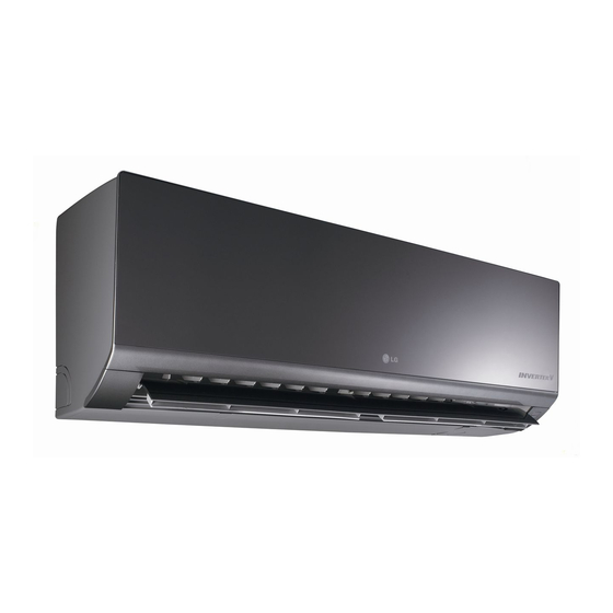
INSTALLATION MANUAL
AIR CONDITIONER
• Please read this installation manual completely before installing the product.
• Installation work must be performed in accordance with the national wiring
standards by authorized personnel only.
• Please retain this installation manual for future reference after reading it
thoroughly.
This product contains Fluorinated Greenhouse Gases. (R410A)
TYPE : WALL MOUNTED
Original instruction
P/NO : MFL67855414
ТОО "Everest climate", Р. К., г.Алматы | Телефон: +7 727 230 00 10, +7 777 250 10 90 | www.aircon.kz, e-mail: info@aircon.kz
www.lg.com
Advertisement

Related Manuals for LG Artcool Mirror AM07BP


Summary of Contents for LG Artcool Mirror AM07BP
- Page 1 This product contains Fluorinated Greenhouse Gases. (R410A) TYPE : WALL MOUNTED Original instruction www.lg.com P/NO : MFL67855414 ТОО "Everest climate", Р. К., г.Алматы | Телефон: +7 727 230 00 10, +7 777 250 10 90 | www.aircon.kz, e-mail: info@aircon.kz...
- Page 2 TIPS FOR SAVING ENERGY TIPS FOR SAVING ENERGY Here are some tips that will help you minimize the power consumption when you use the air conditioner. You can use your air conditioner more efficiently by referring to the instructions below: •...
-
Page 3: Important Safety Instructions
IMPORTANT SAFETY INSTRUCTIONS IMPORTANT SAFETY INSTRUCTIONS READ ALL INSTRUCTIONS BEFORE USING THE APPLIANCE. Always comply with the following precautions to avoid dangerous situations and ensure peak performance of your product WARNING It can result in serious injury or death when the directions are ignored CAUTION It can result in minor injury or product damage when the directions are ignored WARNING... - Page 4 IMPORTANT SAFETY INSTRUCTIONS • There is a risk of fire and explosion. - Inert gas (nitrogen) should be used when you check plumbing leaks, cleaning or repairs of pipes etc. If you are using combustible gases including oxygen, product may have the risk of fires and ex- plosions.
-
Page 5: Table Of Contents
TABLE OF CONTENTS TABLE OF CONTENTS TIPS FOR SAVING INSTALLATION MAP ENERGY INSTALLATION IMPORTANT SAFETY Select the best Location INSTRUCTIONS Fixing Installation Plate Drill a Hole in the Wall Flaring Work INSTALLATION PARTS Connecting the Piping Checking the Drainage Test Running INSTALLATION TOOLS ТОО... -
Page 6: Installation Parts
INSTALLATION PARTS INSTALLATION PARTS Name Quantity Shape Installation plate 1 EA The feature can be changed according to type of model. Type "A" screw 5 EA Type "B" screw 2 EA Type "C" screw 2 EA Remote control 1 EA holder Screws for fixing panels are attached to decoration panel. - Page 7 MAPPA DI INSTALLAZIONE MAPPA DI INSTALLAZIONE Piastra di installazione Manicotto ( ) Bussola-Manicotto ( ) Mastice (sigillante gomma) ( ) Piegare il tubo quanto più possibile vicino alla parete ma fare attenzione a non romperlo. Nastro adesivo (largo) ( ) •...
- Page 8 INSTALLAZIONE INSTALLAZIONE Scelta della posizione migliore Fissaggio della piastra di installazione - Non deve esserci alcuna fonte di calore o va- pore vicino all'unità. Il muro scelto deve essere forte e solido suffi- - Selezionare un posto in cui non vi sono osta- cientemente da evitare vibrazioni.
- Page 9 INSTALLAZIONE Praticare un foro nella parete Rimozione delle sbavature Rimuovere ogni sbavatura dalla sezione - Forare il foro della tubatura mediante un tra- tagliata in trasversale del tubo. pano con punta da ø65 mm. Forare il foro della tubatura sul lato destro o sinistro; il foro Nel rimuovere le sbavature, posizionare deve essere leggermente inclinato sul lato l’estremità...
- Page 10 INSTALLAZIONE Rimuovere il supporto dei tubi. Maniglia Rimuovere il coperchio della porta dei tubi Barra Barra e posizionare i tubi. Forcella Cono Vista laterale posteriore unità interna Tubo in rame Maniglia di presa Contrassegno di freccia rossa Sinistra Verifica Supporto tubatura Destra Confrontare la svasatura con la figura in basso.
- Page 11 INSTALLAZIONE Errato Installazione dell’unità interna - Il seguente tipo di piegatura direttamente da Appendere l’unità interna sulla parte supe- destra a sinistra può danneggiare la tubatura. riore della piastra di installazione (fissare i tre ganci nella parte superiore dell’unità in- terna al bordo superiore della piastra di in- stallazione).
- Page 12 INSTALLAZIONE ATTENZIONE <Per la tubatura laterale destra> Se il tubo flessibile di scarico viene dire-tto all'interno della stanza, isolarlo con del ma- teriale isolante* in modo che il gocciola- mento derivante dalla condensa non danneggi mobilia o pareti. * Consigliato polietilene espanso o equivalente. Vista Collegamento del tubo di instal- 1(L) 2(N)
-
Page 13: Installation
INSTALLATION Wrap the insulation material Finishing the indoor unit around the connecting portion. installation Overlap the connection pipe insulation ma- Mount the tubing holder in the original terial and the indoor unit pipe insulation positon. material. Bind them together with vinyl Ensure that the hooks are properly seated tape so that there may be no gap. -
Page 14: Checking The Drainage
INSTALLATION Checking the Drainage Do not make drain piping like the follow- ing. To check the drainage. Pour a glass of water on the evaporator. Do not raise Ensure the water flows through the drain hose of the indoor unit without any leak- age and goes out the drain exit. -
Page 15: Test Running
INSTALLATION Test Running - Check that all tubing and wiring are properly connected. - Check that the gas and liquid side service valves are fully open. Prepare remote controller Remove the battery cover by pulling it ac- cording to the arrow direction. Insert new batteries making sure that the (+) and (–) of battery are installed correctly. - Page 16 ТОО "Everest climate", Р. К., г.Алматы | Телефон: +7 727 230 00 10, +7 777 250 10 90 | www.aircon.kz, e-mail: info@aircon.kz...
- Page 17 [Representative] LG Electronics Inc. EU Representative Krijgsman 1, 1186 DM Amstelveen, The Netherlands [Manufacturer] LG Electronics Inc. Changwon 2nd factory 84, Wanam-ro, Seongsan-gu, Changwon-si, Gyeongsangnam-do, KOREA ТОО "Everest climate", Р. К., г.Алматы | Телефон: +7 727 230 00 10, +7 777 250 10 90 | www.aircon.kz, e-mail: info@aircon.kz...
Need help?
Do you have a question about the Artcool Mirror AM07BP and is the answer not in the manual?
Questions and answers