Table of Contents
Advertisement
Quick Links
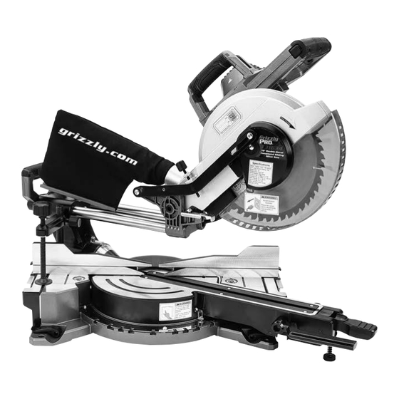
MODEL T31634/T31635
10"/12" DOUBLE-BEVEL
COMPOUND SLIDING MITER SAW
OWNER'S MANUAL
(For models manufactured since 8/19)
184892
COPYRIGHT © NOVEMBER, 2019 BY GRIZZLY INDUSTRIAL, INC.
WARNING: NO PORTION OF THIS MANUAL MAY BE REPRODUCED IN ANY SHAPE
OR FORM WITHOUT THE WRITTEN APPROVAL OF GRIZZLY INDUSTRIAL, INC.
#CS20597 PRINTED IN CHINA
V1.11.19
Advertisement
Table of Contents


Need help?
Do you have a question about the T31634 and is the answer not in the manual?
Questions and answers