
Related Manuals for Comm Net Systems TPA 250 Fuse Panel Series

Summary of Contents for Comm Net Systems TPA 250 Fuse Panel Series
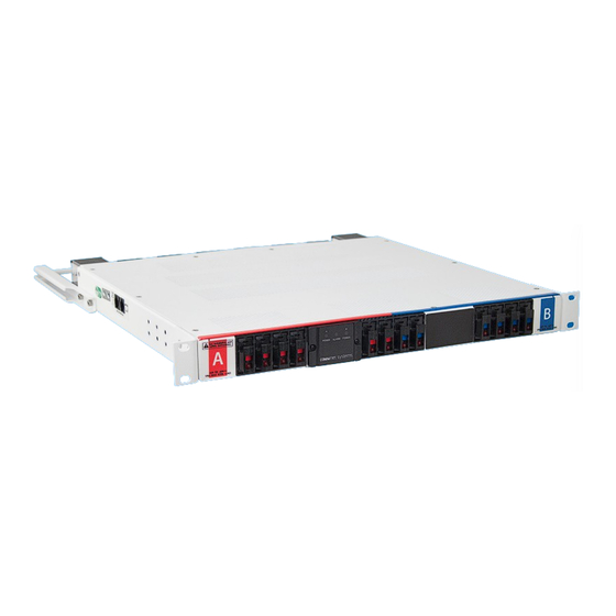
- Page 1 TPA 250 Fuse Panel F O R T E L E C O M B R O A D B A N D SETUP AND OPERATION MANUAL...
- Page 2 Comm/net Systems, Inc.® 4237 – 24th Avenue West Seattle, WA 98199 TEL: 206.282.8670 FAX: 206.282.8684 www.commnetsystems.com 24/7 Sales & Service To purchase Comm/net Systems solutions, contact your Comm/net Systems representative at: (800) 274-0544 or e-mail: sales@commnetsystems.com About Comm/net Systems Comm/net Systems, Inc.® (CSI) is the leader in high power density communications power systems.
- Page 3 TPA 250 Fuse Panel F O R T E L E C O M B R O A D B A N D SETUP AND OPERATION MANUAL...
- Page 4 About This Manual To reduce the risk of damage to equipment, injury, or death; and to ensure proper installation and operation of Comm/net Systems products, please be sure to read and understand the entirety of this manual and any other supplied documentation. Keep this document in a safe and accessible place for future reference.
-
Page 5: Table Of Contents
Table of Contents ..............Section 1: Purpose and Applicability 1.1 Product Model . - Page 6 THIS PAGE INTENTIONALLY LEFT BLANK TPA 250 FUSE PANEL SETUP AND OPERATION MANUAL PAGE vI -...
-
Page 7: Section 1: Purpose And Applicability
Section 1: Purpose and Applicability The purpose of this document is to detail the installation and operation instructions for the TPA 250 Series fuse panel. 1.1 Product Model This document applies to the following configurations of the Comm/net Systems, Inc TPA 250 Series fuse panel: TAbLE 1. - Page 8 THIS PAGE INTENTIONALLY LEFT BLANK TPA 250 FUSE PANEL SETUP AND OPERATION MANUAL PAGE 2 - PURPOSE AND APPLIcAbILITy...
-
Page 9: Section 3: Unpacking And Inspection
Section 3: Unpacking and Inspection The Comm/net Systems TPA 250 Series fuse panel was carefully packaged at the factory to withstand the normal rigors of shipping. However, you should carefully inspect the box and contents to confirm that no damage has occurred in transit. Most shipping carriers require notification of shipping damage within twenty-four hours of delivery, and it is the responsibility of the recipient to inspect the shipment immediately upon receipt. -
Page 10: Mounting
4.2 Mounting NOTICE y THIS PRODUCT MUST bE INSTALLED WITHIN A RESTRICTED ACCESS LOCATION WHERE ACCESS IS THROUGH THE USE OF A TOOL, LOCK AND KEY, OR OTHER MEANS OF SECURITY, AND IS CONTROLLED bY THE AUTHORITY RESPONSIbLE FOR THE LOCATION. THIS PRODUCT MUST bE INSTALLED AND MAINTAINED ONLY bY QUALIFIED TECHNICIANS. -
Page 11: Chassis Ground
4.3 Chassis Ground CAUTION DO NOT ENERGIZE THE PANEL bEFORE CHASSIS GROUND IS CONNECTED. WARNING DO NOT USE HARDWARE WITH A LENGTH EXCEEDING 3/4 INCH FOR CHASSIS GROUND CONNECTIONS. The chassis ground is located on both sides of the panel. Two-hole lug landing positions are provided. -
Page 12: Safety Covers
WARNING FAILURE TO REINSTALL THE INPUT SAFETY COVERS WILL CREATE AN ELECTRICAL HAZARD. Included with each TPA 250 series fuse panel are (4) input safety covers which are designed to help isolate the input terminations. Step 1. Align the notch found on the included plastic safety covers with the slots located at the rear of the panel. -
Page 13: Fuse Installation
4.7 Fuse Installation NOTICE y USE bUSSMANN TPA TYPE FUSES ONLY. y FUSES MUST CARRY A 10kA OR HIGHER INTERRUPT RATING. Step 1. Ensure that connected loads are in the off position, then firmly insert a TPA fuse of sufficient ampacity into the position to be fed (see Figure 12). Step 2. - Page 14 THIS PAGE INTENTIONALLY LEFT bLANK TPA 250 FUSE PANEL SETUP AND OPERATION MANUAL PAGE 8 - INSTALLATION...
- Page 15 Section 5: Operation 5.1 LED Display Modules with the LED display include three indicators: A Power, B Power, Alarm. 5.1.1 A Power LED The A Power LED will light up when power is present on the A input bus. 5.1.2 b Power LED The B Power LED will light up when power is present on the B input bus.
- Page 16 THIS PAGE INTENTIONALLY LEFT bLANK TPA 250 FUSE PANEL SETUP AND OPERATION MANUAL PAGE 10 - OPERATION...
- Page 17 Section 6: Product Specifications 6.1 Electrical Specifications NOTICE USE bUSSMANN TPA TYPE FUSES ONLY. FUSES MUST CARRY A 10kA INTERRUPT RATING. TAbLE 5. TPA 250 SERIES FUSE PANEL SPECIFICATIONS MODELS: MODELS: 016-2121-10 016-2122-10 016-2123-10 016-2124-10 016-2125-10 016-2126-10 016-2127-10 016-2128-10 Type of Input Single Input Dual Input (A/B) Circuits...
-
Page 18: Appendix A: Mechanical Drawings
Appendix A: Mechanical Drawings FRONT VIEW 1.720 LED MODULE METER MODULE REAR VIEW A INPUT B INPUT RETURN RETURN 1.000 40A CONNECTORIZED OUTPUTS 100A CONNECTORIZED OUTPUTS TPA 250 FUSE PANEL TPA 250 FUSE PANEL SETUP AND OPERATION MANUAL SETUP AND OPERATION MANUAL PAGE 12 - PRODUcT SPEcIFIcATIONS PAGE 12... - Page 19 SIDE VIEW TPA 250 FUSE PANEL TPA 250 FUSE PANEL SETUP AND OPERATION MANUAL SETUP AND OPERATION MANUAL PRODUcT SPEcIFIcATIONS - PAGE 13 PAGE 13...
- Page 20 TOP VIEW 18.000 16.000 17.000 TPA 250 FUSE PANEL TPA 250 FUSE PANEL SETUP AND OPERATION MANUAL SETUP AND OPERATION MANUAL PAGE 14 - PRODUcT SPEcIFIcATIONS PAGE 14...
- Page 21 REAR SUPPORT KIT (MINIMUM DEPTH) TPA 250 FUSE PANEL TPA 250 FUSE PANEL SETUP AND OPERATION MANUAL SETUP AND OPERATION MANUAL PRODUcT SPEcIFIcATIONS - PAGE 15 PAGE 15...
- Page 22 REAR SUPPORT KIT (MAXIMUM DEPTH) TPA 250 FUSE PANEL TPA 250 FUSE PANEL SETUP AND OPERATION MANUAL SETUP AND OPERATION MANUAL PAGE 16 - PRODUcT SPEcIFIcATIONS PAGE 16...
-
Page 23: Appendix B: Supported Lugs For Termination
Appendix b: Supported Lugs For Termination TAbLE 6. CHASSIS GROUND CONNECTIONS WIRE GAUGE LUG BARREL TYPE COMM/NET PART MANUFACTURER MANUFACTURER PART CRIMP DIE REQUIRED (HYDRAULIC) NUMBER NUMBER #4 AWG Long 538-085-10 Burndy YAZV4C2TC14FX Burndy U4CRT, W4CRT, W4CVT, X4CRT TAbLE 7. INPUT CONNECTIONS WIRE GAUGE LUG BARREL TYPE COMM/NET PART... -
Page 24: Appendix C: Output Cable Whips
Appendix C: Output Cable Whips Note: All cable assemblies are unterminated unless otherwise specified. For more connectorized output harness lengths and color combinations, please contact Comm/net Systems sales. C.1 40A Output Connector Cable Whips (For 016-2121-10, 016-2122-10, 016-2123-10, 016-2124-10 Models) TAbLE 8. -
Page 25: 100A Connector Cable Whips
C.2 100A Connector Cable Whips (For 016-2125-10, 016-2126-10, 016-2127-10, 016-2128-10 Models) TAbLE 9. 100A OUTPUT CONNECTOR CAbLE WHIPS LENGTH COLOR PART NUMBER (RTN) Red/Black 745-400-10 Blue/Black 745-461-10 Red/Red Tracer 745-263-10 (-48V) 7’ Blue/Blue Tracer 745-264-10 Red/black 100A connector cable assembly Red/Black 745-377-10 Blue/Black... -
Page 26: Appendix D: Supported Fuses
Appendix D: Supported Fuses TAbLE 10. SUPPORTED TPA FUSES PART NUMBER DESCRIPTION 460-060-10 3A TPA Fuse; DC-170V; .58" x 1.5" w/indicator 460-061-10 5A TPA Fuse; DC-170V; .58" x 1.5" w/indicator 460-062-10 10A TPA Fuse; DC-170V; .58" x 1.5" w/indicator 460-063-10 15A TPA Fuse;... - Page 27 THIS PAGE INTENTIONALLY LEFT BLANK...
- Page 28 About Comm/net Systems Corporate Headquarters 24/7 Sales & Service Comm/net Systems, Inc.® (CSI) is the leader in high power density Comm/net Systems, Inc.® To purchase Comm/net Systems solutions, contact your communications power systems. Comm/net offers comprehensive 4237 – 24th Avenue West Comm/net Systems representative at: (800) 274-0544 power and communications site systems integration and deployment Seattle, WA 98199...
Need help?
Do you have a question about the TPA 250 Fuse Panel Series and is the answer not in the manual?
Questions and answers