Table of Contents
Advertisement
Quick Links
Eastman
®
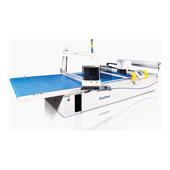
THE EASTMAN
Raptor
WARNING
This machine is equipped with a very sharp
knife. Keep hands, arms, and hair away from
the knife area at all times.
Misuse of this machine or failure to follow all
safety instructions on this machine and in the
instruction manual may result in serious per-
sonal injuries.
779 Washington St., Buffalo, N.Y. 14203-1396 U.S.A. • (716)856-2200 • Fax (716)856-1140 or (716)856-2068
Form E-564
®
Service Manual
Please read completely before attempting
to operate your new Raptor.
Manufacturers of Eastman Cloth Cutting and Cloth Spreading Machines
www.EastmanCuts.com
Technical Support:
1-800-872-5595
Eastman
Over a Century of Cutting Expertise
®
Advertisement
Table of Contents

Subscribe to Our Youtube Channel
Related Manuals for EASTMAN Raptor


Summary of Contents for EASTMAN Raptor
- Page 1 Eastman ® sonal injuries. Over a Century of Cutting Expertise 779 Washington St., Buffalo, N.Y. 14203-1396 U.S.A. • (716)856-2200 • Fax (716)856-1140 or (716)856-2068 Manufacturers of Eastman Cloth Cutting and Cloth Spreading Machines www.EastmanCuts.com Form E-564...
- Page 2 This warranty should not apply if defects are caused by product misuse or neglect, if the machine has been altered or modified by the buyer or if other than genuine Eastman parts are used in the machine. THIS WARRANTY IS APPLICABLE TO THIS PURCHASE ONLY.
-
Page 3: Table Of Contents
Operators must be cautioned that improper or careless use of this equipment may cause personal injury. If you do not have qualified operators to instruct new persons, contact your Eastman sales representative or Eastman factory direct. Disconnect electrical power source before proceeding with any installation, adjustment or repair of the Automated Cutting System. -
Page 4: Safety Information
The purchaser agrees to defend, protect, indem- ing proper use or misuse of the machine. Failure nify, and hold Eastman Machine Company and its to follow these procedures may result in serious subsidiaries harmless from and against all claims, personal injury to the user. -
Page 5: Maintenance
Proper Maintenance will help to ensure the reliable opera- tion of your Raptor. You should allow 5 to 10 minutes for daily inspection, 30 minute weekly inspection and one hour monthly inspection. Time invested on these tasks will minimize downtime. - Page 6 Check all belts for signs of wear such as cuts, frays or missing teeth. Replace if needed. Before performing the bi-weekly tasks make sure the Raptor and computer are turned off at the • Check belt tension. Belt should be tight enough to electrical disconnect and locked out.
-
Page 7: Lubrication Chart
Lubrication Chart Below are the lubrication points for the Raptor. Lubrication Chart 2000 Maintenance Frequency Tool Head Linear Bearings Linear Guides Machine Conveyor Recipricating Tool Tool Component Gantry Y-Car Table Gantry Head Head Bearings Spline Location ID Action to Clean & Lube... -
Page 8: Raptor Label Locations
Eastman ® Raptor Label Locations ITEM PART NO. DESCRIPTION QTY. 91-26004 Decal, Large Eastman 91-26003 Decal, Medium Eastman 91-26073-6 Decal, Gaurd Removal Large 4 91-26073-11 Decal, Entanglement Hazard 2 91-26073-2 Decal, Hazard Voltage 91-26073-9 Decal, Moving Parts 91-26117 Decal Sheet, Plastic Overlay 2... -
Page 9: Raptor Gantry Label Locations
Raptor Gantry Label Locations ITEM PART NO. DESCRIPTION QTY. 91-26002 Decal, Small Eastman 91-26099 Decal, Raptor Logo (Blue) 91-26073-5 Decal, Guard Removal Med. 2 91-26073-2 Decal, Hazard Voltage 91-26073-10 Decal, Pinch Point 91-26073-3 Decal, Blade Hazard 91-26073-4 Decal, Guard Removal Sm. -
Page 10: Aligning, Cleaning And Replacing Consumable Parts
Parts Knife Replacement Sharpening Disc Sharpening Removing the Knife 1. Turn the Power off to the Raptor, use lockout/ tagout if required. 2. Loosen the two Socket Head Screws, Removing the Sharpening Pads Socket Head Screw 1. Turn the Power off to the Gantry, use lockout/ tagout if required. -
Page 11: Sharpener Angle Adjustment
3. Manually push the Presser Foot down and slide the Guide Shaft Spacer to the Guide Sharp Knife is exposed. When handling the Shaft. Sharpener, use caution. Knife Guide Shaft Spacer 54-28797 Presser Foot Guide Assembly Shaft Eastman ® Over a Century of Cutting Expertise Form E-564... - Page 12 Eastman ® 4. Slide the Sharpener to the right as far as it will NOTE: Sharpening Pads should make contact go without bending the blade. with the angled surface on the knife. Should not deflect blade. 7. After adjusting position with the Stop Set Screw, tighten the Jam Nut to lock the stop position of the Sharpener.
-
Page 13: Drill Bit Replacement
4. Rotate Bushing Release Shaft 180 degrees. 5. Lift the Bushing up. Removing the Drill Bit 1. Turn the Power off to the Raptor, use lockout/ tagout if required. 2. Lift the Collar up to Release the Drill Bit. NOTE: Collar will only move approximately 5mm. -
Page 14: Drill Sizes
Eastman ® Drill Sizes 54-28629-X Item Part No. Description Qty. See Chart Drill Adapter See Chart Drill 342-M3-4 Screw,Skt.Set M3-.5 X 4 Flat 2 Hole Size Drill no.(2) Description Adapter no.(1) Assembly no. 3/32"(.094") 54-28631-093 3/32" Closed End Drill Ass'y... -
Page 15: Drill Bushing Sizes
13mm 54-28569-13 Drill Bushing, Ø13.0mm 14mm 54-28569-14 Drill Bushing, Ø14.0mm 15mm 54-28569-15 Drill Bushing, Ø15.0mm 16mm 54-28569-16 Drill Bushing, Ø16.0mm 17mm 54-28569-17 Drill Bushing, Ø17.0mm 18mm 54-28569-18 Drill Bushing, Ø18.0mm Eastman ® Over a Century of Cutting Expertise Form E-564... -
Page 16: Serpentine Belt Replacement
Eastman ® Serpentine Belt Replacement 4. Remove (4) Countersunk Screws and Finish- ing Washers. 1. Turn the Power off to the Raptor, use lockout/tagout if required 2. Unclip Cover Latches on each side and rotate the front cover upwards. Countersunk... - Page 17 9. Pull Motor and Bracket approximately 20mm or 1" to remove the belt. 7. Loosen Top Tension Bolt. Tension Bolt Motor Bracket NOTE: Motor is connected to cables. Handle with care. Eastman ® Over a Century of Cutting Expertise Form E-564...
- Page 18 Eastman ® 12. When installing new Serpentine belt, be sure to line up the (2) sets of markings. The mark- 10. Remove (4) Socket Head Screws and Lock ings are located on the top of the Reciprocat- Washers to remove the Drive Assembly Cover.
-
Page 19: Crank Bearing And Ball Joint Replacement
Crank Bearing and Ball Joint Replacement 5. Remove the (2) Socket Head Screws and Lock Washers that secure the Stabilizer Bracket. 1. Turn the Power off to the Raptor, use lockout/tagout if required Stabilizer Bracket 2. Unclip Cover Latches on each side and rotate the front cover upwards. - Page 20 Eastman ® 7. Remove Socket Head Screw from top of the Crank. Hold the Crank Shaft by inserting a Push up from the bottom and pull the pin in the bottom of the Crank Shaft to prevent Reciprocating Knife assembly out from spinning.
- Page 21 NOTE: Bearings must be pressed in flush to the Crank surface. 6. Assemble in reverse order. NOTE: 1. Crank Step must face outward. 2. Locating Pin Must slide through mating Bearings slot. Eastman ® Over a Century of Cutting Expertise Form E-564...
- Page 22 Eastman ® Ball Joint Removal 3. The top of the Ball Joint requires a 14mm wrench and the Crank requires a 12mm wrench. 1. The Ball Joint is threaded at the Top The Wedge Washer must be replaced anytime and the Bottom. Specific wrench sizes disassembled.
-
Page 23: Theta Belt Replacement
Rotate the Belt Tension Arm with Idler Pulley counter-clockwise to release the tension on the Theta belt. Belt Tension 1. Turn the Power off to the Raptor, use lockout/tagout if required. 2. Remove knife using knife removal procedure. Loosen the (2) Hex Nuts and the single Socket Head Screw. -
Page 24: Air Filter Replacement
Eastman ® Air Filter Replacement Removing the Air Filter 1. Turn the Power off to the Raptor, use lockout/tagout if required. 2. Remove (4) Flanged Screws to remove the Filter Cover. As Shown Slide out the Filter Bracket and Air Filters. -
Page 25: Bristle Block Replacement
Bristle Block 67-27016 67-27016 67-27016-WH 67-27016-WH Slat Slat Bristle Block Installation Bristle Block Removal NOTE: Use only "Genuine" Eastman Bristle Blocks. Failure may result in machine damage and void your warranty. Eastman ® Over a Century of Cutting Expertise Form E-564... -
Page 26: Plastic Overlay Replacement
Eastman ® 3. Loosen the Shaft Collar Screw and remove large Plastic Overlay Replacement core stop disk. NOTE: 1. Plastic Overlay Roll weigh Approximately 150lbs. Core Stop 2. Two people are required for Plastic Overlay Disk replacement. 1. Unhook leather strap. -
Page 27: Take-Off Drive Conveyor Belt Replacement
Take-Off Drive Conveyor Belt Replacement 5. Loosen (4) mounting Screws as shown. 1. Turn the Power off to the Raptor, use lockout/tagout if required 2. The Drive belt is located on the operator side of the take off conveyor. Begin by Removing (4) Flanged Screws. -
Page 28: X-Motor Belt Replacement
NOTE: Use same procedure for both Operator tension. Side and Non-Operator Side. Operator side is shown. 1. Turn the Power off to the Raptor, use lockout/tagout if required. Remove (2) Countersunk Screws and (2) Finishing Washers to remove the pause paddle. -
Page 29: Replacement Of X-Car Drive Gear
(Operator Side Only) NOTE: This replacement is for the Operator Side. The Non-Operator Side follows the same steps but requires the Bearing Housing to be turned "Clockwise" instead of Counter-Clockwise. Eastman ® Over a Century of Cutting Expertise Form E-564... - Page 30 Eastman ® 5. Remove X-Car Drive Assembly. 8. Re-install New X-Car Drive Pulley and Key. X-Car Drive Assembly X-Car Drive Gear 6. Remove (2) Set Screws from X-Car NOTE: Use Loctite 680 (Green) on shaft when installing Drive Gear. X-Car Drive Gear.
-
Page 31: Blower Belt Replacement
Tension Arm to swing back into position once the belt is removed. NOTE: Use same procedure for both 30HP and 40HP Blower. 1. Turn the Power off to the Raptor, use lockout/tagout if required. Spring 2. Remove (10) Screws to remove Cover. -
Page 32: Replacing Multi Axis Controller Card And Loading Configuration Files
Replacing Multi Axis Controller Card and Loading Configuration Files The Raptor uses one Z Controller card located inside the Computer. The Z controller card com- municates over the purple network cables with all of the Motor Amplifiers and the Slice Input/ Output (IO) cards. -
Page 33: Amplifier Error Codes
There was an error writing to a E0099 file on the SD card. SD card read/write in prog- Wait until read/write process is E0100 ress. done. Reserved. Eastman ® Over a Century of Cutting Expertise Form E-564... - Page 34 Eastman ® Fault Message/Warning Cause Remedy Firmware type mismatch. Installed firmware is not compatible Load compatible firmware into F101 with the drive hardware. drive. The FPGA is a lab FPGA. The FPGA is a lab version FPGA. Load the released FPGA ver-...
- Page 35 24V n140 the drive. DRV.NVSAVE command and after power supply in order to reboot the rebooting the drive. drive or restore the original setting of VBUS.HALFVOLT. Eastman ® Over a Century of Cutting Expertise Form E-564...
- Page 36 Eastman ® Fault Message/Warning Cause Remedy Not enough distance to For trapezoidal and customer table Activation of any new motion or us- move; motion exception. motion tasks: The target velocity ing of DRV.CLRFAULTS will clear specified in the motion task cannot the warning.
- Page 37 1:1 profile table motion task be started from velocity 0. Activation n169 while another motion task is cur- of any new motion or using of DRV. rently running. CLRFAULTS will clear the warning. Eastman ® Over a Century of Cutting Expertise Form E-564...
- Page 38 Eastman ® Fault Message/Warning Cause Remedy Customer profile table is Appears with n160, when you Ap- Change theMT.TNUM parameter not initialized. pears with n160, when you uses a for this specific motion task in order customer profile table for generating to use an initialized profile table.
- Page 39 SFD feedback fault. Bad communication with the SFD Check primary feedback (X10). device. If fault persists, internal feedback F408 to F416 failure. Return to manufacturer for refund. Eastman ® Over a Century of Cutting Expertise Form E-564...
- Page 40 Eastman ® Fault Message/Warning Cause Remedy "Broken wire in primary "In primary feedback, a broken Check feedback cable continuity. F417 feedback." wire was detected (incremental encoder signal amplitude)." Primary feedback power "Power supply fault for primary Check primary feedback (X10).
- Page 41 "F479 Wake and Shake. Loop "The angle between complete "Modify WS.IMAX orWS.T and try n479" angle delta too large. loops was larger than 72 deg." again." Eastman ® Over a Century of Cutting Expertise Form E-564...
- Page 42 Eastman ® Fault Message/Warning Cause Remedy Fieldbus command "Fieldbus command velocity exceeds "Lower fieldbus command trajectory, F480 velocity too high. VL.LIMITP." or increase the value of VL.LIMITP." Fieldbus command "Fieldbus command velocity exceeds "Increase fieldbus command trajec- F481 velocity too low.
- Page 43 "IV current offset limit Hardware failure detected. Restart Drive. If issue persists, con- F530 exceeded." tact technical support. Power stage fault. Hardware failure detected. Restart Drive. If issue persists, Re- F531 place Drive. Eastman ® Over a Century of Cutting Expertise Form E-564...
- Page 44 Eastman ® Fault Message/Warning Cause Remedy Drive motor parameters Before a motor can be enabled, Issue the command DRV.SETU- setup incomplete. you must configure aminimum PREQLIST to display the list set of parameters. These of the parameters that youmust parameters have not been config- configure.
- Page 45 Writing to read-only param- User program attempted writing a read-only parameter. F827 eter. Disable Drive first. User program is attempting to execute a function that requires the drive to be F828 disabled. Eastman ® Over a Century of Cutting Expertise Form E-564...
-
Page 46: Amplifier Error And Alarm Codes
Eastman ® Amplifier Error and Alarm Codes Faults/Errors and Warnings/Alerts are displayed in the 7 segment displays of the drive: To simplify handling, the error and alarm handling process is consistent, so you can always apply the same recovery steps. When an error or alarm occurs, it is displayed to the one digit display, you can identify the error in the table below and follow the recommendations to fix the problem, clear the display, and resume machine operation. - Page 47 "EtherCAT communi- "EtherCAT network operation "Check the EtherCAT network wiring and de- cation failure during failed due to a network commun- vices state. Re-start the application." bootstrap mode." ciation error." Eastman ® Over a Century of Cutting Expertise Form E-564...
- Page 48 Eastman ® Fault Message/Warning Cause Remedy "EtherCAT failed to "EtherCAT network initialization Check the EtherCAT network wiring and de- initialize into opera- failed due to a network commun- vices state. Re-start the application. tional mode." ciation error." "EtherCAT failed to "EtherCAT network initialization...
- Page 49 Local digital IO was not update dur- Reduce the sample rate, simplify the missed a cyclic ing a cycle or the updates are no application, or reduce the application update" longer synchronous. cycles. Eastman ® Over a Century of Cutting Expertise Form E-564...
-
Page 50: Troubleshooting The Servo Motor Drives
Eastman ® Troubleshooting the Servo Motor Drives Drive problems occur for a variety of reasons, depending on the conditions in your installation. The causes of faults in multi-axis systems can be especially complex. If you cannot resolve a fault or other issue using the trouble shooting guidance presented below, customer support can give you further assistance. -
Page 51: Yearly Maintenance Checklist For Raptor
Yearly Maintenance Checklist for Raptor Below is the recommended maintenance checklist for the Raptor. It provides a good guideline for yearly maintenance and can be copied and kept as a maintenance log. Comments Signoff Raptor Machine Check painted surfaces for scratches... - Page 52 Eastman ® Comments Signoff Tool Head Assembly Inspect Theta Motor drive belt (cracks,etc) Grease Bearings -See Lube Chart Inspect & Oil Drill lift bearing Test Theta proximity sensor Secure Theta Motor drive pulley set screws Examine cylinder motion Inspect the knife intellicut system for...
- Page 53 Bristle Conveyor Examine surface for damaged bristles Inspect edge seals for damage Check excessive wear on drive sprockets Inspect Bristle drive bearings. See Lube Chart Inspect condition of roller bed surface Eastman ® Over a Century of Cutting Expertise Form E-564...
- Page 54 Eastman ® Comments Signoff Y-Carriage Assembly Check wiring and cables for and wear Check all screw terminals to ensure wiring is secure Examine Solenoid Block(Pressure regulator, valve body, flow control valve and air lines a) Check for air leaks Check and secure all set screws...
- Page 55 Check & secure gear rack screws Check & secure all remaining hard- ware Check & secure linear rail & oil or grease rail as required. See Lube Chart. Eastman ® Over a Century of Cutting Expertise Form E-564...
-
Page 56: Technical Data
200cm 244cm 284cm 200cm 249cm 7.5cm 779 Washington St., Buffalo, N.Y. 14203-1396 U.S.A. • (716)856-2200 • Fax (716)856-1140 or (716)856-2068 Manufacturers of Eastman Cloth Cutting and Cloth Spreading Machines www.EastmanCuts.com Form E-564 ©2012 Eastman Machine Company Printed in U.S.A. 9/2014...
Need help?
Do you have a question about the Raptor and is the answer not in the manual?
Questions and answers