Table of Contents
Advertisement
EASTMAN
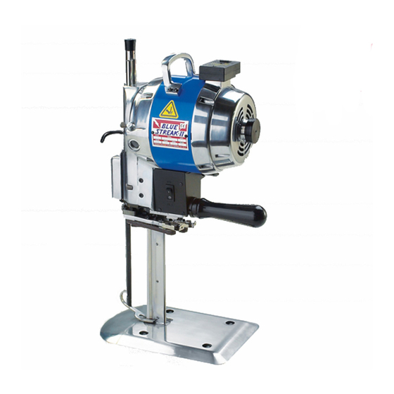
BLUE STREAK
BRUTE
779 Washington St., Buffalo, N.Y. 14203-1396 U.S.A. • (716) 856-2200 • Fax (716) 856-1140 or (716) 856-2068
Form C-1572
®
CE Approved
Model 627XS Auto-Stop
Website: www.EastmanCuts.com
II
CE Approved
®
Model 629XS Auto-Stop
Instruction Manual
and Parts List
Blue Streak II Model 629XS Auto-Stop
Brute Model 627XS Auto-Stop
Serial # _____________________________
WARNING
This machine is equipped with a very sharp knife.
Keep hands, arms, and hair away from the knife
area at all times.
Misuse of this machine or failure to follow all safety
instructions on this machine and in the instruction
manual may result in serious personal injuries.
Advertisement
Table of Contents

Related Manuals for EASTMAN BLUE STREAK II


Summary of Contents for EASTMAN BLUE STREAK II
- Page 1 BRUTE CE Approved Model 627XS Auto-Stop Instruction Manual and Parts List Blue Streak II Model 629XS Auto-Stop Brute Model 627XS Auto-Stop Serial # _____________________________ WARNING This machine is equipped with a very sharp knife. Keep hands, arms, and hair away from the knife area at all times.
- Page 2 EASTMAN Limited Warranty. Eastman warrants to the buyer that the Blue Streak II and Brute shall be free from defects in materials or workmanship for a period of 180 days commencing on the date of invoice. Any goods or parts claimed by the buyer to be defective must be returned to Eastman, freight charges prepaid, within the 180–day warranty period.
-
Page 3: Table Of Contents
IMPORTANT This manual contains instructions and part numbers for two Patents Statement different machines: Brute Model 627XS and Blue Streak II Some parts of this manual and the equipment it describes Model 629XS. If you contact Eastman Machine Company are protected by the following U.S. patents: 5,178,232, for information or to order parts, always specify the ma- 4,609,244, 5,111,582, 4,761,878, and D281,416. - Page 4 Figure 25. Front Bearing Housing with Oiler Figure 7. Changing the Knife ........9 Assembly (Exploded View) ......27 Figure 8. Available Eastman Knife Types ....10 Figure 26. Sharpener Housing Assembly (Assembled, Front View) ......28 Figure 9. Adjusting Bevel Bloc Shoes ......11 Figure 27.
-
Page 5: Safety Information
• Safety labels must be kept clean and legible at all hazards arising from the use or misuse of the ma- times. Call the Eastman Machine factory to order chine. In addition to such training, the purchaser replacement labels. -
Page 6: Operation
EASTMAN Operation CAUTION Operating this machine from an incorrect electrical Before operating the machine, read these instructions care- supply may damage it. fully. Familiarize yourself with all the functions and adjust- ments of the machine. 2. Check that the machine has been lubricated according to the schedule listed in Routine Maintenance–Lubrica-... -
Page 7: Operating Procedure
• How to disconnect power from the machine. If you are not familiar with any of these points, ask your supervisor or contact an Eastman representative. 2. Check the condition of your machine and working area. Make sure that: •... -
Page 8: Starting The Machine
EASTMAN Starting the Machine Turning Off the Machine If you have had the machine less than one month or if it When you have finished using your machine: has stood idle for any length of time, turn the motor on and 1. -
Page 9: Weekly
1. Take the machine out of the lay. CAUTION 2. Drop the knife guard/pressure foot using the pressure Use only specially compounded Eastman 30-weight, foot lever (Figure 2, R on page 3), located next to the non-detergent oil. Use of sewing machine oil or deter- machine operating handle. -
Page 10: Replacing The Rubber Driver Pulley
EASTMAN 5. Press the lever (Figure 3, E) to a neutral position and raise the sharpener to the top (original) position. 6. Remove the four hold-down nuts (Figure 3, V), unplug solenoid cord and remove the sharpener. Note: If you press the sharpener lever (Figure 3, E) down too far (beyond the neutral position), it will lock the sharpener bracket. -
Page 11: Adjusting The Belt Sharpener
Adjusting the Belt Sharpener Adjusting Stabilizers for Central Alignment 1. Disengage the attachment plug, if you have not already Note: You can obtain all the special tools you will require done this. for adjusting the sharpener by ordering tool kit #820C2. 2. -
Page 12: Checking The Sharpener Shoes
EASTMAN 5. Remove the locknut (Figure 6, 3). Checking the Extreme Down Position of the Sharpener The correct down position is with the tip of the knife at the 6. Install gauge C189 on the exposed threaded end of the center of the belt on the shoe (Figure 6, 12). -
Page 13: Checking The Stop Screw On The Sharpener Shoe
5. When the spacer is adjusted, use the pin to hold the Changing the Knife spacer in position, reassemble, and tighten the locknut (Figure 6, 15). WARNING 6. Replace the plastic cap. Always handle knives with care. Safely dispose of used knives. -
Page 14: Figure 8. Available Eastman Knife Types
1. Make sure the sharpener is in the locked position. Note: For best results, use only Eastman knives. The limited warranty covering your machine is not valid if 2. Lay the machine on a table, as shown in Figure 7. -
Page 15: Adjusting Bevel Bloc Shoes
Adjusting Bevel Bloc Shoes ® Eastman’s exclusive, patented adjustable Bevel Bloc sharp- ener shoes make it possible to grind any desired bevel on the knife edge. The knife-edge bevel on your new machine is factory set to handle all normal fabrics and normally should not be changed. -
Page 16: Figure 10. Bevel Bloc Shoe Assembly
EASTMAN Adjusting Bevel Bloc Shoes (continued) ® If you need to adjust the bevel on the knife edge to a differ- ent length, proceed as follows: 1. Disconnect the machine from the power source. 2. Lower the knife to the bottom of the stroke with the machine turning knob (Figure 2, F on page 3). -
Page 17: Figure 11. Maintenance Supplies
Allen Wrench for Shoe Set Screws 34C10-145 Spring Shoe L.H. 242C2-2 Eastman Bearing Grease 34C10-146 Spring Shoe R.H. 162C2 Oil Can 95C5-3 Wrench, Allen 242C1* 1/2 Pint Eastman Oil 95C5-5* Wrench, Allen 81C1-2 Slot Cleaner 103C2-35 Shoe, Sharpener R.H. 103C2-36 Shoe, Sharpener L.H. *Optional 308C10-1* Screw, Socket 6/32"... -
Page 18: Troubleshooting
EASTMAN Troubleshooting PROBLEM SOLUTION PROBLEM SOLUTION Motor overheats a. Cut out switch not engaging Machine does not a. Surface of cutting table not properly move easily on table smooth b. Lint and dust inside motor b. Rubber mounted rollers com-... -
Page 19: Figure 12. Electrical Configuration
Figure 12. Electrical Configuration Form C-1572... -
Page 20: Freeing Frozen Guides
EASTMAN Freeing Frozen Guides 8. Place a fiber or brass rod against the bottom of the crosshead and drive the crosshead out through the top of the guides. Note: If the wrist pin is frozen in the crosshead, drive the wrist pin out of the crosshead with a soft punch. -
Page 21: Ordering Details
The circular motion of the knife could pull the glove toward the blade. Genuine Eastman Abrasive Belts Eastman’s four abrasive belt grits offer an edge for every fabric. For increased cutting efficiency, Eastman offers four different edges as produced by four different abrasive belts. -
Page 22: Ergo-Handle
Figure 16. Edges Produced by Different Belt Grits Ergo-Handle Available as an option on new machines or for retrofitting to any existing Eastman straight knife, the Ergo-Handle al- lows the operator to adjust the handle downward from the standard horizontal through a 14-degree range. Adjusting the handle’s angle to suit the operator’s preference allows... -
Page 23: Specialty Machines
Specialty Machines Micro Fog Model 627XSMF/629XSMF Eastman's Micro Fog is designed for the same purpose as Plastic Master Model 627XSPM/629XSPM the Plastic Master, but is more comprehensive. The exclu- Eastman's Plastic Master has been specifically designed sive Micro Fog and a 90-120 psi compressed air hose sends... -
Page 24: Illustrated Parts List
Illustrated Parts List Lower Gear Bracket Assembly See pages 32 and 33. Your Eastman Straight Knife has been carefully designed Note: Four different abrasive belt grits (designed to pro- to provide many hours of trouble-free operation. The com- vide you with a selection of edges) may be ordered for this prehensive exploded parts illustrations have been carefully machine. -
Page 25: Figure 20. Exploded Assembly View
SHARPENER HOUSING ASSEMBLY (FRONT VIEW) SEE PAGES 28 AND 29 20C3-38 SHARPENER 20C3-39 HOUSING ASSEMBLY (REAR VIEW) SEE PAGES 30 AND 31 4C1-179 MOTOR ASSEMBLIES SEE PAGES 22, 23, 24 AND 25 4C1-99 FRONT BEARING HOUSING ASSEMBLY KNIFE SEE PAGES 26 AND 27 4C1-150 20C13-96 PAGES... -
Page 26: Figure 21. Single-Phase Motor Assembly
EASTMAN Single-Phase Motor Assemblies Part No. No. Req'd Description 52C5-238 Switch Base 52C5-239 Fuse Base 53C7-35 Fan Cover 73C7-121 Terminal Wire Tubing 79C2-82 Label, Safety Warning 79C2-84 Label, Safety Warning 90C1-146 Rear Bearing Housing 90C6-46 Rear Ball Bearing 236C-177 Label, Warning Figure 21. -
Page 27: Figure 22. Single Phase Motor Assembly (Exploded View)
Attachment Plug Note: L.H. indicates left- WARNING Terminal Block hand thread. All others are See Back Cover Attach ground wire to ground terminal right-hand. “E” on Terminal block. Failure to ground Terminal block may result in electrocution or other serious personal injuries. -
Page 28: Figure 23. Three-Phase Motor Assembly
EASTMAN Three-Phase Motor Assemblies Part No. No. Req'd Description 1C4-8 Sleeve, Cutout 4C1-145 Shaft Lock Nut 4C2-87 Nut, Clutch 10C1-41 Rotor Fan 12C1-12 Loading Spring Washer 12C1-32 Lock Washer 13C1-9 Turning Knob 18C6-16 Retaining Ring 20C13-94 Screw, M4 Pan Head... -
Page 29: Figure 24. Three-Phase Motor Assembly (Exploded View)
Attachment Plug WARNING Note: L.H. indicates left- Terminal Block hand thread. All others are Attach ground wire to ground terminal See Back Cover right-hand. “E” on Terminal block. Failure to ground Terminal block may result in electrocution or other serious 20C13-94 580C1-98 personal injuries. - Page 30 EASTMAN Front Bearing Housing (90C2-165) with Oiler Assembly Part No. No. Req'd Description 62C1-140 Handle Bracket 63C5-11 Push Button Cap 71C3-18 Front Ball Bearing Retainer 72C4-28 Oil Hole Cover 73C7-203 Oil Tube, Clear 73C7-204 Oiler Tube 85C1-52 Crank-1-1/8 Stroke 85C1-46...
-
Page 31: Figure 25. Front Bearing Housing With Oiler
Note: Certain 220 volt machines will 706C1-4 110 Volt 53C11-180 706C1-5 220 Volt use these capacitors. Please check 706C1-13 110 Volt the capacitor number on label of your 706C1-18 220 Volt machine to order. 308C12-1 34C10-142 4C2-110 305C8-1 660C4-14 660C4-15 660C4-16 72C4-28 53C11-183... -
Page 32: (Assembled, Front View)
EASTMAN Sharpener Housing Assembly Part No. No. Req'd Description (Front View) For both 627 & 629 4C1-149 Nut, Elastic 4C2-112 R.H. Nut for Screw Shaft 4C2-113 L.H. Nut for Screw Shaft 5C5-16 Collar, Lower 11C12-54 Shaft for Cam 12C15-57 Spring Washer for Release Lever... - Page 33 *THESE PARTS SOLD ONLY IN ASSEMBLIES AS FOLLOWS. 713C4-4 Screw Shaft with Extension, R. & L. Hand Nuts 5"-8" 713C4-5 Screw Shaft with Extension, R. & L. Hand Nuts 9"-10" 86C7-34 713C4-6 Screw Shaft with Extension, R. & L. Hand Nuts 11 1/2" Spacer 713C4-7 Screw Shaft with Extension, R.
-
Page 34: Figure 28. Sharpener Housing Assembly
EASTMAN Sharpener Housing Assembly (Rear View) Part No. No. Req'd Description For both 627 & 629 4C2-2 Lock Nut for Shaft 4C2-85 R.H. Follower Nut 4C2-86 L.H. Follower Nut 11C12-58 R.H. Square Shaft 5"-8" Knife 11C12-59 R.H. Square Shaft 9"-10" Knife 11C12-81 R.H. -
Page 35: Figure 29. Sharpener Housing Assembly (Exploded, Rear View)
R.H. SQUARE SHAFTS Spacer Chart 11C12-58 5"-8" Knife For Automatic Sharpeners 11C12-59 9"-10" Knife Stroke Knife Spacer Spacer 11C12-81 11 1/2" Knife Size Number Length 11C12-85 13" Knife 1 1/8-1 1/4 73C7-55 3 7/8 TUBES FOR SQUARE SHAFTS 1 1/2-1 3/4 73C7-56 4 1/4 73C7-46... -
Page 36: Figure 30. Lower Gear Bracket Assembly
EASTMAN Lower Gear Bracket Assembly Complete Sharpener Assembly Numbers: 637C10-* Machine Stroke Illustrated Parts List 1-1/8" 1-1/4" 1-1/2" 1-3/4" 5" -20, -21, -22, -23, 6" -24, -25, -26, -27, 7" -28, -29, -30, -31, 8" -32, -33, -34, -35, 9"... - Page 37 Note: L.H. indicates left-hand thread. All others are right-hand. Figure 31. Lower Gear Bracket Assembly (Exploded View) Form C-1572...
-
Page 38: Figure 32. Standard And Baseplate Assembly
EASTMAN Standard and Baseplate Assembly Part No. No. Req'd Description For both 627 & 629 12C1-35 Lock Washer, #8 12C15-77 Washer for Micro Fog Standard 17C1-4 Taper Pin #0 x 3/4 17C6-9 Hinge Pin 20C5-12 Clamp Screw for Rollers 20C12-19... -
Page 39: Figure 33. Standard And Baseplate Assembly
INSTRUCTIONS FOR REMOVING WORN PLATE ROLLER SHELL Figure 34. Removing a Worn Plate Roller Shell CAUTION Do not oil the plate roller shells or you may dam- age them. Place the plate on blocks and press out the roller shell from the ring assembly (Figure 34). NOTE: A roller shell (complete with shaft and bearings) may be ordered as required. -
Page 40: Electrical Connections
— Terminal Contact w/Pin L3 667C1-28 — — — — 779 Washington St., Buffalo, N.Y. 14203-1396 U.S.A. • (716) 856-2200 • Fax (716) 856-1140 or (716) 856-2068 Website: www.EastmanCuts.com Form C-1572 © 1996 Eastman Machine Company Printed in U.S.A. 9/2007...
Need help?
Do you have a question about the BLUE STREAK II and is the answer not in the manual?
Questions and answers