Table of Contents
Advertisement
Quick Links
MODEL G0495X
8" X 83" JOINTER
w/DIGITAL HEIGHT READOUT
OWNER'S MANUAL
(For models manufactured since 07/19)
COPYRIGHT © MARCH, 2008 BY GRIZZLY INDUSTRIAL, INC., REVISED AUGUST, 2019 (JL)
WARNING: NO PORTION OF THIS MANUAL MAY BE REPRODUCED IN ANY SHAPE
OR FORM WITHOUT THE WRITTEN APPROVAL OF GRIZZLY INDUSTRIAL, INC.
#BL10436 PRINTED IN TAIWAN
V5.08.19
Advertisement
Table of Contents

Related Manuals for Grizzly G0495X


Summary of Contents for Grizzly G0495X
- Page 1 OWNER'S MANUAL (For models manufactured since 07/19) COPYRIGHT © MARCH, 2008 BY GRIZZLY INDUSTRIAL, INC., REVISED AUGUST, 2019 (JL) WARNING: NO PORTION OF THIS MANUAL MAY BE REPRODUCED IN ANY SHAPE OR FORM WITHOUT THE WRITTEN APPROVAL OF GRIZZLY INDUSTRIAL, INC.
- Page 2 This manual provides critical safety instructions on the proper setup, operation, maintenance, and service of this machine/tool. Save this document, refer to it often, and use it to instruct other operators. Failure to read, understand and follow the instructions in this manual may result in fire or serious personal injury—including amputation, electrocution, or death.
-
Page 3: Table Of Contents
Table of Contents INTRODUCTION ..........2 SECTION 5: ACCESSORIES ......31 Contact Info............ 2 SECTION 6: MAINTENANCE ......33 Manual Accuracy ........... 2 Schedule ............33 Identification ........... 3 Cleaning ............33 Controls & Components ......... 4 Unpainted Cast Iron ........33 Machine Data Sheet ........ -
Page 4: Introduction
ID label (see below). This information is required for us to provide proper tech support, and it helps us determine if updated documenta- tion is available for your machine. Manufacture Date Serial Number Model G0495X (Mfd. Since 07/19) -
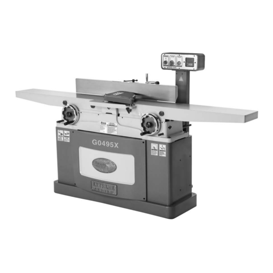
Page 5: Identification
K. Tilt Lock D. Cutterhead Guard Digital Sensor E. Fence Tilt Handle M. Infeed Depth Stops Control Panel with Digital Readout N. Infeed Handwheel G. Depth Scale O. Outfeed Handwheel H. Infeed Table P. Outfeed Depth Stops Model G0495X (Mfd. Since 07/19) -
Page 6: Controls & Components
Controls & Components Figure 2. Control panel and digital readout features. A. POWER Light E. Digital Display B. STOP Button ON/OFF HOLD TO CAL BUTTON Button C. START Button G. ABS/INC D. Battery Compartment H. MM/IN Model G0495X (Mfd. Since 07/19) -
Page 7: Machine Data Sheet
Machine Data Sheet MACHINE DATA SHEET Customer Service #: (570) 546-9663 · To Order Call: (800) 523-4777 · Fax #: (800) 438-5901 MODEL G0495X 8" X 83" HELICAL CUTTERHEAD JOINTER WITH EXCLUSIVE DIGITAL HEIGHT READOUT Product Dimensions: Weight................................596 lbs. - Page 8 The information contained herein is deemed accurate as of 3/11/2020 and represents our most recent product specifications. Model G0495X PAGE 2 OF 3 Model G0495X (Mfd. Since 07/19) Due to our ongoing improvement efforts, this information may not accurately describe items previously purchased.
-
Page 9: Section 1: Safety
Never operate under the influence of drugs or injury or blindness from flying particles. Everyday alcohol, when tired, or when distracted. eyeglasses are NOT approved safety glasses. Model G0495X (Mfd. Since 07/19) - Page 10 EXPERIENCING DIFFICULTIES. If at any time debris. Make sure they are properly installed, you experience difficulties performing the intend- undamaged, and working correctly BEFORE ed operation, stop using the machine! Contact our operating machine. Technical Support at (570) 546-9663. Model G0495X (Mfd. Since 07/19)
-
Page 11: Additional Safety Instructions For Jointers
Straight knives should never project MAXIMUM CUTTING DEPTH. To reduce risk of more than ⁄ " (0.125") from cutterhead body. kickback, never cut deeper than ⁄ " per pass. Model G0495X (Mfd. Since 07/19) -
Page 12: Section 2: Power Supply
To reduce the risk of these hazards, avoid over- loading the machine during operation and make sure it is connected to a power supply circuit that meets the specified circuit requirements. -10- Model G0495X (Mfd. Since 07/19) - Page 13 Minimum Gauge Size ......12 AWG all local codes and ordinances. Maximum Length (Shorter is Better)..50 ft. -11- Model G0495X (Mfd. Since 07/19)
-
Page 14: Section 3: Setup
IMPORTANT: Save all packaging materials until weight of this machine. you are completely satisfied with the machine and have resolved any issues between Grizzly or the shipping agent. You MUST have the original pack- aging to file a freight claim. It is also extremely helpful if you need to return your machine later. -
Page 15: Inventory
Push Blocks ..........2 K. T-Handle T-25 Torx Driver ......2 L. Inserts 15 x 15 x 2.5 ........5 M. Flat Head Torx Screws #10-32 ....10 N. AAA Batteries (not shown) ......2 -13- Model G0495X (Mfd. Since 07/19) - Page 16 Repeat Steps 2–3 as necessary until clean, then coat all unpainted surfaces with a quality metal protectant to prevent rust. -14- Model G0495X (Mfd. Since 07/19)
-
Page 17: Site Considerations
Only install in an Shadows, glare, or strobe effects that may distract access restricted location. or impede the operator must be eliminated. 83" 24½" Figure 6. Minimum working clearances. -15- Model G0495X (Mfd. Since 07/19) -
Page 18: Moving & Placing Jointer
The Model G0495X requires the use of lifting equipment such as a forklift, engine hoist, or Anchoring to Concrete Floors boom crane. DO NOT try to lift the machine by Lag shield anchors with lag screws (see below) hand. -
Page 19: Dust Collection
Setting Outfeed Table Height The outfeed table height MUST be level with the DO NOT operate the Model G0495X without carbide inserts when they are at top-dead-center. an adequate dust collection system. This If the outfeed table is set too low, the workpiece jointer creates substantial amounts of wood will be tapered from front to back. -
Page 20: Digital Readout Batteries
The cutterhead guard is a critical safety feature of this jointer. You MUST verify its operation before using the jointer! Failure to properly install this guard will greatly increase risk of serious personal injury. -18- Model G0495X (Mfd. Since 07/19) -
Page 21: Test Run
DO NOT start machine until all preceding setup instructions have been performed. Operating an improperly set up machine may result in malfunction or unexpect- ed results that can lead to serious injury, death, or machine/property damage. -19- Model G0495X (Mfd. Since 07/19) -
Page 22: Recommended Adjustments
The STOP button safety feature is not working correctly. This Verify V-Belt Tension Adjustment (Page 44). safety feature must work properly before proceeding with regular operations. Call Tech Support for help. -20- Model G0495X (Mfd. Since 07/19) -
Page 23: Section 4: Operations
Read books/magazines or get formal training before beginning any proj- ects. Regardless of the content in this sec- tion, Grizzly Industrial will not be held liable for accidents caused by lack of training. Figure 14. START/STOP button locations. - Page 24 Figure 17. Tilt lock and stop block locations. Fence Adjustment Lock Wheel Figure 16. Fence lock location. -22- Model G0495X (Mfd. Since 07/19)
-
Page 25: Digital Readout
-0.010". Press ABS/INC button to toggle back to absolute mode. The screen displays 0.115", the total depth of cut relative to absolute zero point set in Step 2. -23- Model G0495X (Mfd. Since 07/19) -
Page 26: Stock Inspection & Requirements
This machine is NOT designed to cut metal, glass, stone, tile, products with lead-based paint, or prod- ucts that contain asbestos—cutting these materials with a jointer may lead to injury. -24- Model G0495X (Mfd. Since 07/19) -
Page 27: Squaring Stock
Rip Cut on a Table Saw—Jointed edge Surface Plane on Jointer—Concave face of of workpiece is placed against a table saw workpiece is surface planed flat with jointer. fence and opposite edge cut off. Previously Jointed Edge -25- Model G0495X (Mfd. Since 07/19) -
Page 28: Surface Planing
Figure 21. Example photo of a surface planing Repeat Step 6 until entire surface is flat. operation. Tip: When squaring up stock, cut opposite side of workpiece with a planer instead of the jointer to ensure boths sides are parallel. -26- Model G0495X (Mfd. Since 07/19) -
Page 29: Edge Jointing
Repeat Step 6 until the entire edge is flat. Tip: When squaring up stock, cut opposite edge of workpiece with a table saw instead of the jointer—otherwise, both edges of work- piece will not be parallel with each other. -27- Model G0495X (Mfd. Since 07/19) -
Page 30: Bevel Cutting
45°. your hands safe, DO NOT let them get closer than 4" from moving cutterhead at any time during operation! Repeat cutting process, as necessary, until you are satisfied with the results. -28- Model G0495X (Mfd. Since 07/19) -
Page 31: Rabbet Cutting
However, it is possible to make rabbet cuts with workpieces up to 1" thick without removing the cutterhead guard. This is done by performing the rabbet cut with the workpiece on end (similar to when you are edge jointing). -29- Model G0495X (Mfd. Since 07/19) - Page 32 Use push blocks whenever practical to further reduce risk of accidental hand contact with cutterhead. Repeat Step 7 until rabbet is cut to depth. Re-install cutterhead guard if removed in Step 3. -30- Model G0495X (Mfd. Since 07/19)
-
Page 33: Section 5: Accessories
W1015—Y-Fitting 4" x 4" x 4" To reduce this risk, only install accessories W1017—90° Elbow 4" recommended for this machine by Grizzly. W1019—Hose Coupler (Splice) 4" W1317—Wire Hose Clamp 4" NOTICE W1007—Plastic Blast Gate 4"... - Page 34 Figure 29. Recommended products for protect- ing unpainted cast iron/steel part on machinery. Figure 31. Instructional reference book. www.grizzly.com 1-800-523-4777 order online at or call -32- Model G0495X (Mfd. Since 07/19)
-
Page 35: Section 6: Maintenance
® Lubrication For optimum performance from this machine, this maintenance schedule must be strictly followed. Since all bearings on the G0495X are sealed and Ongoing permanently lubricated, simply leave them alone To maintain a low risk of injury and proper until they need to be replaced. -
Page 36: Section 7: Service
3. Inspect/replace belt with a new one (refer to Page 3. V-belt worn or loose. 44). 4. Pulley is loose. 4. Realign/replace shaft, pulley, setscrew, and key as required. 5. Motor mount loose/broken. 5. Tighten/replace. -34- Model G0495X (Mfd. Since 07/19) - Page 37 4. Insufficient number of passes. 4. It may take 3 to 5 passes to achieve a perfect edge, depending on the starting condition of the board and the depth of cut. -35- Model G0495X (Mfd. Since 07/19)
-
Page 38: Checking/Adjusting Table Parallelism
Correct the outfeed table parallelism, then correct the infeed table parallelism. -36- Model G0495X (Mfd. Since 07/19) - Page 39 0.010"-0.012", then adjust the infeed table parallel with the outfeed table. When setting the outfeed table, all measurements must be made from the cutterhead body—not the inserts. -37- Model G0495X (Mfd. Since 07/19)
- Page 40 0.010"-0.012". Note: Setting the outfeed table parallel to the cutterhead within 0.010"-0.012" will produce high quality results. Going lower than this Figure 42. Infeed and outfeed tables adjusted number will produce minimal gain. even. -38- Model G0495X (Mfd. Since 07/19)
-
Page 41: Replacing Carbide Inserts
Figure 43). Note: Excess oil may squeeze between the insert and cutterhead or in the screw hole, thereby lifting the insert or screw slightly and Reference Dot affecting workpiece finishes. Figure 43. Insert rotating sequence. -39- Model G0495X (Mfd. Since 07/19) -
Page 42: Setting Infeed Table
Setting Infeed Table Calibrating Infeed Table The infeed table on the Model G0495X has posi- tive stop bolts that, when properly set up, allow The depth scale on the infeed table can be cali- the operator to quickly adjust the infeed table brated or "zeroed"... -
Page 43: Checking/Adjusting Cutterhead Guard
Figure 46. Cutterhead guard components. Holding guard height in place, tighten shaft lock to secure setting. Repeat Step 2 and, if necessary, repeat Steps 3–4 until cutterhead guard is properly adjusted. -41- Model G0495X (Mfd. Since 07/19) -
Page 44: Setting Fence Stops
Retighten the jam nut loosened in Step 4. Re-install the fence assembly on the jointer. Remove the fence assembly, re-install the plate with the screws removed in Step 1, then re-install the fence assembly. -42- Model G0495X (Mfd. Since 07/19) - Page 45 Adjust the 90˚ fence stop bolt until it makes contact with the 90˚ stop block. Retighten the jam nut loosened in Step 2. Retighten the jam nut loosened in Step 3. -43- Model G0495X (Mfd. Since 07/19)
-
Page 46: Adjusting/Replacing V-Belt
Figure 54. Tension Rod Pulley Figure 55. Checking V-belt tension. Fasteners Replace the rear access panel and the V-belt guard. Figure 54. Fasteners needed to be loosened for V-belt replacement. -44- Model G0495X (Mfd. Since 07/19) -
Page 47: Pulley Alignment
Tighten the motor mount fasteners. The V-belt should be parallel and aligned as Figure 56. Checking belt alignment. shown in Figure 57. Re-install the fence assembly, rear access panel, and V-belt guard. -45- Model G0495X (Mfd. Since 07/19) -
Page 48: Section 8: Wiring
Technical Support at (570) 546-9663. The photos and diagrams included in this section are best viewed in color. You can view these pages in color at www.grizzly.com. -46- Model G0495X (Mfd. Since 07/19) -
Page 49: Electrical Components
Electrical Components Figure 60. Capacitor wiring. Figure 59. Magnetic switch wiring. READ ELECTRICAL SAFETY -47- Model G0495X (Mfd. Since 07/19) ON PAGE 46! -
Page 50: Wiring Diagram
Always use the wiring diagram inside the motor junction box. See Figure 60 Ground Motor Motor Junction Box Figure 61. Junction box wiring. READ ELECTRICAL SAFETY -48- Model G0495X (Mfd. Since 07/19) ON PAGE 46 ! -
Page 51: Section 9: Parts
SECTION 9: PARTS We do our best to stock replacement parts when possible, but we cannot guarantee that all parts shown are available for purchase. Call (800) 523-4777 or visit www.grizzly.com/parts to check for availability. Fence REF PART # DESCRIPTION... -
Page 52: Base
168V2-8 168V2-11 168V2 168V2-7 168V2-13 168V2-6 168V2-14 168V2-5 168V2-15 168V2-12 168V2-16 168V2-4 168V2-3 168V2-18 168V2-17 168V2-19 168V2-2 168V2-20 168V2-21 168V2-1 98V2 BUY PARTS ONLINE AT GRIZZLY.COM! -50- Model G0495X (Mfd. Since 07/19) Scan QR code to visit our Parts Store. - Page 53 SET SCREW M6-1 X 8 P0495X166 CAP SCREW 10-24 X 1/2 P0495X174 BUTTON HD CAP SCR M6-1 X 16 P0495X167 FLAT WASHER 8MM BUY PARTS ONLINE AT GRIZZLY.COM! -51- Model G0495X (Mfd. Since 07/19) Scan QR code to visit our Parts Store.
-
Page 54: Table
BUTTON HD CAP SCR M6-1 X 12 P0495X057 HEX BOLT 3/8-16 X 1-1/4 P0495X215 ROLL PIN 4 X 10 P0495X058 CUTTERHEAD GUARD LOCK HANDLE BUY PARTS ONLINE AT GRIZZLY.COM! -52- Model G0495X (Mfd. Since 07/19) Scan QR code to visit our Parts Store. -
Page 55: Stand
119V2 102V2-13 102V2 103 2 102V2-12 102V2-15 149V3 141V3 147-1 147V3 142V3 125-1 125-4 125-2 125-3 125-5 148V2 125-6V2 128V2 125-7 BUY PARTS ONLINE AT GRIZZLY.COM! -53- Model G0495X (Mfd. Since 07/19) Scan QR code to visit our Parts Store. - Page 56 PHLP HD SCR M3-.5 X 8 P0495X112 HEX BOLT 3/8-16 X 6 P0495X195 PHLP HD SCR M6-1 X 8 P0495X113 HEX NUT M5-.8 BUY PARTS ONLINE AT GRIZZLY.COM! -54- Model G0495X (Mfd. Since 07/19) Scan QR code to visit our Parts Store.
-
Page 57: Labels & Cosmetics
Safety labels help reduce the risk of serious injury caused by machine hazards. If any label comes off or becomes unreadable, the owner of this machine MUST replace it in the original location before resuming operations. For replacements, contact (800) 523-4777 or www.grizzly.com. BUY PARTS ONLINE AT GRIZZLY.COM! -55- Model G0495X (Mfd. -
Page 59: Warranty & Returns
WARRANTY & RETURNS Grizzly Industrial, Inc. warrants every product it sells for a period of 1 year to the original purchaser from the date of purchase. This warranty does not apply to defects due directly or indirectly to misuse, abuse, negligence, accidents, repairs or alterations or lack of maintenance.
Need help?
Do you have a question about the G0495X and is the answer not in the manual?
Questions and answers