Table of Contents
Advertisement
Quick Links
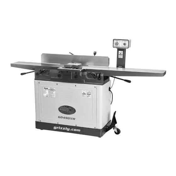
MODEL G0490W/G0490XW
8" X 76" JOINTER
w/PARALLELOGRAM BEDS
OWNER'S MANUAL
(For models manufactured since 05/16)
COPYRIGHT © FEBRUARY, 2016 BY GRIZZLY INDUSTRIAL, INC. REVISED SEPTEMBER, 2016 (BL)
WARNING: NO PORTION OF THIS MANUAL MAY BE REPRODUCED IN ANY SHAPE
OR FORM WITHOUT THE WRITTEN APPROVAL OF GRIZZLY INDUSTRIAL, INC.
#BL17848 PRINTED IN CHINA
V2.09.16
Advertisement
Table of Contents

Subscribe to Our Youtube Channel
Related Manuals for Grizzly G0490W


Summary of Contents for Grizzly G0490W
- Page 1 OWNER'S MANUAL (For models manufactured since 05/16) COPYRIGHT © FEBRUARY, 2016 BY GRIZZLY INDUSTRIAL, INC. REVISED SEPTEMBER, 2016 (BL) WARNING: NO PORTION OF THIS MANUAL MAY BE REPRODUCED IN ANY SHAPE OR FORM WITHOUT THE WRITTEN APPROVAL OF GRIZZLY INDUSTRIAL, INC.
- Page 2 This manual provides critical safety instructions on the proper setup, operation, maintenance, and service of this machine/tool. Save this document, refer to it often, and use it to instruct other operators. Failure to read, understand and follow the instructions in this manual may result in fire or serious personal injury—including amputation, electrocution, or death.
-
Page 3: Table Of Contents
Identification ........... 3 Cleaning & Protecting ........34 Controls & Components ......... 4 Lubrication ........... 35 G0490W Machine Data Sheet ....... 6 G0490XW Machine Data Sheet..... 8 SECTION 7: SERVICE ........36 Troubleshooting ........... 36 SECTION 1: SAFETY ........10 Inspecting Knives (G0490W) ....... -
Page 4: Introduction
ID label (see below). This information is required for us to provide proper tech support, and it helps us determine if updated documenta- tion is available for your machine. Manufacture Date Serial Number Model G0490W/G0490XW (Mfd. Since 5/16) -
Page 5: Identification
Always use hold-down or push blocks when jointing material narrower than 3" or surface planing material thinner than 3". e) Never perform jointing, planing, or rabbeting cuts on pieces shorter than 8" in length. Model G0490W/G0490XW (Mfd. Since 5/16) -
Page 6: Controls & Components
H. Outfeed Table Adjustment Lever: Adjusts reset, motor can be restarted. outfeed table position (when outfeed table lock and positive stop bolts are loosened). B. START Button: Starts motor when pressed (only if STOP button has been reset). Model G0490W/G0490XW (Mfd. Since 5/16) - Page 7 P. Fence Tilt Handle: Tilts fence throughout its range of motion from 45° inward to 45° out- ward (135°). Q. Fence Lock Lever: Tightens to secure fence position along width of tables; loosens to allow lateral adjustment. Model G0490W/G0490XW (Mfd. Since 5/16)
-
Page 8: G0490W Machine Data Sheet
G0490W Machine Data Sheet MACHINE DATA SHEET Customer Service #: (570) 546-9663 · To Order Call: (800) 523-4777 · Fax #: (800) 438-5901 MODEL G0490W 8" JOINTER WITH PARALLELOGRAM BEDS Product Dimensions: Weight................................482 lbs. Width (side-to-side) x Depth (front-to-back) x Height............76-1/2 x 26-1/2 x 45-1/2 in. - Page 9 The information contained herein is deemed accurate as of 9/1/2016 and represents our most recent product specifications. Model G0490W PAGE 2 OF 3 Due to our ongoing improvement efforts, this information may not accurately describe items previously purchased. Model G0490W/G0490XW (Mfd. Since 5/16)
-
Page 10: G0490Xw Machine Data Sheet
The information contained herein is deemed accurate as of 9/1/2016 and represents our most recent product specifications. Model G0490XW PAGE 1 OF 3 Due to our ongoing improvement efforts, this information may not accurately describe items previously purchased. Model G0490W/G0490XW (Mfd. Since 5/16) - Page 11 The information contained herein is deemed accurate as of 9/1/2016 and represents our most recent product specifications. Model G0490XW PAGE 2 OF 3 Due to our ongoing improvement efforts, this information may not accurately describe items previously purchased. Model G0490W/G0490XW (Mfd. Since 5/16)
-
Page 12: Section 1: Safety
Everyday ery. Never operate under the influence of drugs or eyeglasses are NOT approved safety glasses. alcohol, when tired, or when distracted. -10- Model G0490W/G0490XW (Mfd. Since 5/16) - Page 13 EXPERIENCING DIFFICULTIES. If at any time debris. Make sure they are properly installed, you experience difficulties performing the intend- undamaged, and working correctly BEFORE ed operation, stop using the machine! Contact our operating machine. Technical Support at (570) 546-9663. -11- Model G0490W/G0490XW (Mfd. Since 5/16)
-
Page 14: Additional Safety For Jointers
It also ⁄ " (0.125") from cutterhead project more than requires more cutting force, which produces chat- body. ter or excessive chip out. Always joint or surface plane WITH the grain. -12- Model G0490W/G0490XW (Mfd. Since 5/16) -
Page 15: Section 2: Power Supply
To reduce the risk of these hazards, avoid over- loading the machine during operation and make sure it is connected to a power supply circuit that meets the specified circuit requirements. -13- Model G0490W/G0490XW (Mfd. Since 5/16) -
Page 16: Grounding Requirements
Minimum Gauge Size ......12 AWG all local codes and ordinances. Maximum Length (Shorter is Better)..50 ft. -14- Model G0490W/G0490XW (Mfd. Since 5/16) -
Page 17: Section 3: Setup
IMPORTANT: Save all packaging materials until you are completely satisfied with the machine and have resolved any issues between Grizzly or the shipping agent. You MUST have the original pack- aging to file a freight claim. It is also extremely helpful if you need to return your machine later. -
Page 18: Inventory
Inventory (Figures 8–10): A. Jointer Assembly ........1 Figure 8. G0490W/G0490XW inventory—box 1. B. Fence and Carriage Assembly ....1 C. Push Blocks ..........2 D. Service Tools: —... -
Page 19: Cleanup
Figure 11. T23692 Orange Power Degreaser. Repeat Steps 2–3 as necessary until clean, then coat all unpainted surfaces with a quality metal protectant to prevent rust. -17- Model G0490W/G0490XW (Mfd. Since 5/16) -
Page 20: Site Considerations
Only install in an Shadows, glare, or strobe effects that may distract access restricted location. or impede the operator must be eliminated. Wall 30" Minimum Working Clearance " " Figure 12. Minimum working clearances. -18- Model G0490W/G0490XW (Mfd. Since 5/16) -
Page 21: Assembly
Note: Make sure cutterhead pulley is facing to rear of stand. Figure 14. Inserting power cord through stand. -19- Model G0490W/G0490XW (Mfd. Since 5/16) - Page 22 Base 10. Verify alignment of cutterhead and motor pul- leys, as illustrated in Figure 19. Cutterhead Pulley Alignment Motor Figure 21. Fence assembly and carriage Pulley installed. Figure 19. Example of pulleys aligned. -20- Model G0490W/G0490XW (Mfd. Since 5/16)
- Page 23 (see Figure 26), let motor slide down to tension belt, then retighten bolts/ nuts. Figure 23. Loosening front cap screw on key. Figure 26. Motor mount bracket bolts. Figure 24. Loosening rear cap screw on key. -21- Model G0490W/G0490XW (Mfd. Since 5/16)
- Page 24 Otherwise, the workpiece table height must be reset (refer to Setting cannot properly feed past the cutterhead, Outfeed Table Height on Page 46 for which may cause a kickback hazard for the detailed instructions). operator. -22- Model G0490W/G0490XW (Mfd. Since 5/16)
- Page 25 Figure 33. Rabbeting table installed. 21. Insert cutterhead guard shaft into jointer, as shown in Figure 32, so shaft flat is fac- 24. Model G0490W Only: Assemble knife-set- ing set screw, then tighten pre-installed set ting jig, as shown in Figure 34.
-
Page 26: Dust Collection
Note: A tight fit is necessary for proper performance. Push STOP button in (see Figure 36). Connect machine to power supply. STOP START Button Button Figure 35. Dust hose attached to dust port. Figure 36. STOP/START button locations. -24- Model G0490W/G0490XW (Mfd. Since 5/16) -
Page 27: Recommended Adjustments
Figure 37. Resetting the switch. Factory adjustments that should be verified: Push START button to start machine. A cor- • Model G0490W Knife Settings (refer to Page rectly operating machine runs smoothly with 38). little or no vibration or rubbing noises. -
Page 28: Section 4: Operations
Read books/magazines or get formal training before beginning any proj- ects. Regardless of the content in this sec- tion, Grizzly Industrial will not be held liable for accidents caused by lack of training. -26- Model G0490W/G0490XW (Mfd. Since 5/16) -
Page 29: Stock Inspection & Requirements
NOT designed to cut metal, glass, stone, tile, 1" Min. products with lead-based paint, or products Figure 39. Minimum stock dimensions for jointer. that contain asbestos—cutting these materi- als with a jointer may lead to injury. 10" Min. -27- Model G0490W/G0490XW (Mfd. Since 5/16) -
Page 30: Squaring Stock
4. Rip Cut on a Table Saw—The jointed edge of the workpiece is placed against a table saw fence and the opposite edge cut off. Previously Jointed Edge -28- Model G0490W/G0490XW (Mfd. Since 5/16) -
Page 31: Surface Planing
Failure to use push blocks when surface Surface planing could result in your hands contact- ing rotating cutterhead, which will cause Figure 41. Illustration of surface planing results. serious personal injury. ALWAYS use push blocks when surface planing on jointer! -29- Model G0490W/G0490XW (Mfd. Since 5/16) -
Page 32: Edge Jointing
Tip: When squaring up stock, cut opposite edge of workpiece with a table saw instead of the jointer—otherwise, both edges of work- Figure 43. Illustration of edge jointing results. piece will not be parallel with each other. -30- Model G0490W/G0490XW (Mfd. Since 5/16) -
Page 33: Bevel Cutting
DO NOT let them get closer than 4" from moving cutterhead at any time during operation! Repeat cutting process, as necessary, until you are satisfied with the results. Removed Surface Figure 45. Illustration of bevel cutting results. -31- Model G0490W/G0490XW (Mfd. Since 5/16) -
Page 34: Rabbet Cutting
When cutterhead guard is removed, attempting any other cut besides a rab- bet directly exposes operator to moving cutterhead. ALWAYS replace cutterhead guard after rabbet cutting! Figure 48. Illustration of rabbet cutting effects and a few sample joints. -32- Model G0490W/G0490XW (Mfd. Since 5/16) -
Page 35: Section 5: Accessories
The inserts are not only placed in a spiral pattern, they are also positioned at an angle so the shearing Figure 49. Replacement knives for G0490W. action leaves a glassy smooth cut on the toughest and most figured woods. -
Page 36: Section 6: Maintenance
To reduce risk of shock or accidental startup, always disconnect machine from power before adjustments, Cleaning the Model G0490W/G0490XW is rela- maintenance, or service. tively easy. Vacuum excess wood chips and saw- dust, and wipe off the remaining dust with a dry cloth. -
Page 37: Lubrication
Protects against rust and corrosion. Ensures stick-free, smooth motion which maximizes finishes and extends the life of your machine. Won’t gum up! 12 oz. AMGA#2 (ISO 68 Equivalent) Figure 54. SB1365 Way Oil. -35- Model G0490W/G0490XW (Mfd. Since 5/16) -
Page 38: Section 7: Service
4. Pulley loose or not properly aligned. 4. Re-align pulleys; replace shaft key; tighten pulley set screw. 5. Knives/inserts at fault. 5. Resharpen/replace knives; set knife alignment/ height correctly. 6. Cutterhead bearings at fault. 6. Replace bearing(s)/realign cutterhead. -36- Model G0490W/G0490XW (Mfd. Since 5/16) - Page 39 2. Workpiece too uneven at start of operation. 2. Take partial cuts to remove extreme high spots before doing a full pass. 3. Check/adjust table parallelism (Page 44). 3. Tables are not parallel with cutterhead and each other. -37- Model G0490W/G0490XW (Mfd. Since 5/16)
-
Page 40: Inspecting Knives (G0490W)
— If knives do not touch straightedge or they lift up at any position, then those knives need to be adjusted. Figure 58. Example of setting knife heights using straightedge method. -38- Model G0490W/G0490XW (Mfd. Since 5/16) - Page 41 The cutterhead in this jointer is equipped with jack screws that allow for careful positioning of the knives. Figure 62. Using knife-setting jig to set knife height. Loosen Knife Tighten Jack Screw Gib Bolt Figure 61. Cutterhead profile diagram. -39- Model G0490W/G0490XW (Mfd. Since 5/16)
- Page 42 Figure 63. Jack screw access hole. 11. Replace cutterhead guard and cabinet rear 11. Replace cutterhead guard and cabinet rear 11. Replace cutterhead guard and cabinet rear access panel. access panel. access panel. -40- Model G0490W/G0490XW (Mfd. Since 5/16)
-
Page 43: Rotating/Changing
Rotate cutterhead pulley to provide access to raise slightly, making it out of alignment. insert(s) to be rotated/replaced. -41- Model G0490W/G0490XW (Mfd. Since 5/16) -
Page 44: Checking/Adjusting Table Parallelism
Rotate motor pulley so that you can access cutterhead body with straightedge between the knives/inserts, as shown in Figure 68. Straightedge Outfeed Table Figure 68. Adjusting outfeed table even with cutterhead body (knife-style cutterhead shown). -42- Model G0490W/G0490XW (Mfd. Since 5/16) - Page 45 — If straightedge does not sit flat against Figure 70. Infeed and outfeed tables set evenly both infeed and outfeed tables in any of (knife-style cutterhead shown). positions, then follow Adjusting Table Parallelism instructions on next page. -43- Model G0490W/G0490XW (Mfd. Since 5/16)
-
Page 46: Adjusting Table Parallelism
(see MUST be made from the cutterhead body—not Figure 73). the knives/inserts or the results may be skewed. Set Screw Location Eccentric Bushing Figure 73. Eccentric bushing and set screw location. -44- Model G0490W/G0490XW (Mfd. Since 5/16) - Page 47 Place straightedge halfway across infeed and outfeed tables, and adjust infeed table even with outfeed table, as shown in Figure 75. Straightedge Outfeed Table Infeed Table Figure 75. Infeed and outfeed tables set evenly (knife-style cutterhead shown). -45- Model G0490W/G0490XW (Mfd. Since 5/16)
-
Page 48: Setting Outfeed Table Height
G0490W Straightedge Knife-Style Cutterhead Only: Correctly set knife heights (refer to Setting/Replacing Outfeed Infeed Knives (G0490W) on Page 38 for detailed instructions). Loosen outfeed table lock located at front of Bottom Dead machine, and loosen jam nuts and positive G0490XW... -
Page 49: Adjusting Infeed Table Stop Bolts
Figure 81. Infeed table even with outfeed table. Using a screwdriver, loosen pivot screw, adjust scale pointer to "0" (see Figure 82), then re-tighten pivot screw. Scale Pointer Pivot Screw Figure 82. Depth-of-cut scale pointer adjusted to "0". -47- Model G0490W/G0490XW (Mfd. Since 5/16) -
Page 50: Setting Fence Stops
45° inward while resting on screw (verify (check angle with sliding bevel set to 135°), angle with a 45° square), retighten jam nut, then retighten jam and tilt lock. tilt lock, and fence lock. -48- Model G0490W/G0490XW (Mfd. Since 5/16) -
Page 51: Replacing/Tensioning Belt
Press belt with moderate pressure in cen- 87) and replace cabinet rear access panel. ter to check belt tension. Belt is correctly tensioned when there is approximately ⁄ " deflection when pushed, as shown in Figure -49- Model G0490W/G0490XW (Mfd. Since 5/16) -
Page 52: Aligning Pulleys
Replace cabinet rear access panel. DISCONNECT MACHINE FROM POWER! Remove cabinet rear access panel. Visually check alignment of cutterhead and motor pulleys, as illustrated in Figure 89. Cutterhead Pulley Alignment Motor Pulley Figure 89. Example of pulleys aligned. -50- Model G0490W/G0490XW (Mfd. Since 5/16) -
Page 53: Section 8: Wiring
Technical Support at (570) 546-9663. The photos and diagrams included in this section are best viewed in color. You can view these pages in color at www.grizzly.com. -51- Model G0490W/G0490XW (Mfd. Since 5/16) -
Page 54: G0490W/G0490Xw Wiring
TECO Relay RHU-10/1 TEST RC.A 97 NO 98 NO 95 NC 96 NC Ground NEMA 6-20 Plug Motor Start Capacitor CD60 300MFD 250VAC Run Capacitor CBB60 40MFD 450VAC Ground READ ELECTRICAL SAFETY -52- Model G0490W/G0490XW (Mfd. Since 5/16) ON PAGE 51! -
Page 55: Section 9: Parts
P0490W029 HEX NUT M10-1.5 P0490W061 TORSION SPRING 2.5 X 26 X 30MM P0490W030 CAP SCREW M6-1 X 25 P0490W062 SPRING RETAINER P0490W031 BUMPER P0490W063 ROLL PIN 3 X 16 P0490W032 CAP SCREW M10-1.5 X 30 -53- Model G0490W/G0490XW (Mfd. Since 5/16) -
Page 56: Cutterhead (G0490W)
BEARING BLOCK (L) P0490W119 EXT RETAINING RING 10MM P0490W109 BALL BEARING 6203-2RS P0490W120 KNIFE-SETTING JIG FOOT P0490W110 INT RETAINING RING 47MM 120A P0490W120A KNIFE-SETTING JIG 8" P0490W111 BALL BEARING 6204-2RS P0490W121 KNIFE-SETTING JIG SHAFT -54- Model G0490W/G0490XW (Mfd. Since 5/16) -
Page 57: Cutterhead (G0490Xw)
P0490XW106 CAP SCREW M8-1.25 X 70 P0490XW115 COLLAR P0490XW107 LOCK WASHER 8MM P0490XW116 BEARING BLOCK (R) P0490XW108 BEARING BLOCK (L) P0490XW117 CAP SCREW M8-1.25 X 80 P0490XW109 BALL BEARING 6203-2RS P0490XW118 KEY 6 X 6 X 25 -55- Model G0490W/G0490XW (Mfd. Since 5/16) -
Page 58: Fence
RIVET 2 X 6MM NAMEPLATE, STEEL P0490W247 HEX WRENCH 5MM P0490W223 BUSHING 14 X 15 P0490W248 HEX WRENCH 6MM P0490W224 ADJUSTABLE HANDLE 94L, M10-1.5 X 50 P0490W249 HEX WRENCH 8MM P0490W225 ROLL PIN 3 X 20 -56- Model G0490W/G0490XW (Mfd. Since 5/16) -
Page 59: Stand
P0490W346 FLANGE NUT M6-1 P0490W320 HEX BOLT M8-1.25 X 30 P0490W347 HEX BOLT M8-1.25 X 50 P0490W321 GROMMET 12 X 50MM (PLASTIC) P0490W348 REAR WHEEL SLEEVE P0490W324 MAG SWITCH TECO HUF-11K P0490W349 REAR WHEEL -57- Model G0490W/G0490XW (Mfd. Since 5/16) -
Page 60: Labels & Cosmetics
Safety labels help reduce the risk of serious injury caused by machine hazards. If any label comes off or becomes unreadable, the owner of this machine MUST replace it in the original location before resuming operations. For replacements, contact (800) 523-4777 or www.grizzly.com. -58-... - Page 61 Would you recommend Grizzly Industrial to a friend? _____ Yes _____No Would you allow us to use your name as a reference for Grizzly customers in your area? Note: We never use names more than 3 times. _____ Yes _____No 10.
- Page 62 FOLD ALONG DOTTED LINE Place Stamp Here GRIZZLY INDUSTRIAL, INC. P.O. BOX 2069 BELLINGHAM, WA 98227-2069 FOLD ALONG DOTTED LINE Send a Grizzly Catalog to a friend: Name_______________________________ Street_______________________________ City______________State______Zip______ TAPE ALONG EDGES--PLEASE DO NOT STAPLE...
-
Page 63: Warranty & Returns
WARRANTY & RETURNS Grizzly Industrial, Inc. warrants every product it sells for a period of 1 year to the original purchaser from the date of purchase. This warranty does not apply to defects due directly or indirectly to misuse, abuse, negligence, accidents, repairs or alterations or lack of maintenance.
Need help?
Do you have a question about the G0490W and is the answer not in the manual?
Questions and answers