Table of Contents
Advertisement
Quick Links
Advertisement
Table of Contents

Related Manuals for TECHCON SYSTEMS TS9800 Series


Summary of Contents for TECHCON SYSTEMS TS9800 Series
- Page 1 Techcon Systems TS9800 Series Jet Valve User Guide...
-
Page 2: Table Of Contents
CONTENTS Pages SAFETY ………………………………………………………..……. UNPACKING AND INSPECTION ….…………………….……….…. TS9800 SYSTEM DESCRIPTION.…………………………………………... SETUP INSTRUCTIONS 4.1 Mounting & Connection ……………………………………… 4.2 Setup ………………………………………………………….. 9-12 4.3 Nozzle Calibration ……………………………………………. 12-15 OPERATION 5.1 Start Dispensing ……………………………………………….. 5.2 Parameter Settings ……………………………………………. 16-17 HEATING 6.1 Introduction …………………………………………………… 6.2 Safety Instructions ………………………………………………... - Page 3 9.4 Symbol Definitions …………………………………………… 9.5 Operation 9.5.1 Login …………………………………………… 9.5.2 Disable password protection.………………….. 35-36 9.5.3 Enable password protection …………………… 9.5.4 Resetting master password ……………………………. 36-37 9.5.5 Setup dispensing parameters …………………………… 37-39 9.5.6 Calling up dispense parameters………………………. 9.5.7 Reset cycle counter …………………………… 39-40 9.5.8 To run Dot or Line mode ……………….…………..…...
-
Page 4: Safety
• The TS9800 System can be used for dispensing fluids with a wide range of fluid viscosity. • Additional heating may only be carried out with a heating system from Techcon Systems • The usage of the TS9800 System can be carried out under laboratorial or production environment. - Page 5 • The TS9800 System is constructed modularly. If a defect occurs, the effected module should not be interchanged with other parts. The whole system needs to be sent back to Techcon Systems for repair. The cables can stay with the customer but need to be checked. Information of how to check the performance is available from Techcon Systems.
-
Page 6: Unpacking And Inspection
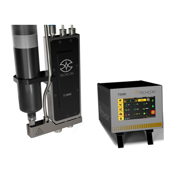
UNPACKING AND INSPECTION Carefully unpack the valve and examine the items contained in the carton. These will include: Jet Valve TS9800 (version shown below is without heater) Jet Valve Controller TS980 Nozzle Insert (order separately) Actuator Cable (3-to-2 pin connectors) Sensor Cable (6-to-5 pin connectors) Heater Cable (4-pin connectors). -
Page 7: Ts9800 System Description
TS9800 SYSTEM DESCRIPTION The TS9800 Series Jet Valve is a Piezoelectric driven, non-contact dispensing valve capable of handling fluid at different viscosities. Jet Valve offers a fast jetting action producing hundreds of accurate deposits less than one second. Every component of the valve was designed to the highest tolerances and manufactured to the strictest degree of precision insuring world class accuracy and repeatability in drop-to-drop dispensing volume. -
Page 8: Setup Instructions
SET-UP INSTRUCTIONS 4.1 Mounting & Connection The TS9800 Series Jet Valve should be used on an automated XYZ table. It is very important that the valve is mounted on the Z-axis gantry, in a secure manner, that will not allow loosening during dispense operation. -
Page 9: Setup
Figure 3: Connection 4.2 Setup WARNING: Before starting the Jet Valve System, carefully read through this user guide and pay attention to the warning and caution notices. Step 1: • Using the provided nozzle adjustment tool (1) to remove the nozzle adjustment nut/bushing assembly (2) and protective nylon washer... - Page 10 Step 3: • Install the nozzle insert (7) to the nozzle bushing. Caution: the smaller end of the nozzle inserts faces outward. • Place the bushing/nozzle insert assembly nozzle installation tool in the vertical position to prevent the nozzle insert from dropping out. Step 4: •...
- Page 11 Step 7: • Mount the syringe bracket (8) by sliding it on the side of the valve, then use the 3mm hex wrench to install the provided M4 screw (9) to secure the bracket in place. • Insert the syringe into the bracket.
-
Page 12: Nozzle Calibration
Step 10: • Turn on the controller by pressing the On/Off switch. Perform the calibration process; this process is to make sure the nozzle insert is placed at the correct position with respect to the tappet. (see next section instructions). 4.3 Nozzle Calibration The nozzle calibration process is to make sure that the nozzle insert is placed at the correct position with respect to the tappet. - Page 13 Step 3: Start the calibration procedure by touching the ‘Calibration’ icon Step 4: Use the nozzle adjustment tool to slowly and gently screw (clockwise) the nozzle unit onto the fluid manifold until it stops against the tappet. Then touch the ‘Start’ icon. Step 3: The system will warm up before starting the calibration computation.
- Page 14 Step 4: Slowly and gently un-screw the nozzle unit (counter-clockwise), using the nozzle adjustment tool if necessary, to move the yellow circle to the center of the green zone. Note: values in the yellow circle are only for reference and it will vary from valve to valve. Caution: The value shown below the green zone does not make a significant difference for the precision of the dispense process if the yellow circle is inside the green zone.
- Page 15 WARNING: Make sure the nozzle insert and nozzle bushing are properly installed in the nozzle unit before starting the calibration process. Never over-tighten the nozzle unit against the tappet since it can break the tappet or cause pre-matured wear on both tappet and nozzle insert. If the yellow circle can’t be moved to or stay inside the green zone, touch the ‘Accept’...
-
Page 16: Operation
OPERATION 5.1 Start Dispensing The valve is now ready to dispense. Dispensing fluid (via cartridge/syringe or reservoir) must be connect the supply pressure regulator. Enter the desired dispensing parameters refer to section 7.5.5 (Rising, Open Time, Falling, Delay, Needle Lift and Number of Pulses), then touch ‘Save’ icon. - Page 17 The essential parameters are: Parameter Description Rise Time This is the time interval in which the valve is open. The time increment is in 1 µs starting at 80 µs. The maximum rising time is 1999 µs. Open Time This value defines the time in which the valve is completely open.
-
Page 18: Heating
HEATING 6.1 Introduction The TS9800 Jet Valve with heating system is available for heating high viscosity fluid. The heating system also helps to maintain constant temperature. Required parts: • TS9800 Jet Valve with heater • Heater Cable 6.2 Safety Instructions •... -
Page 19: Mounting & Connection
6.4 Mounting & Connection ( w/ Heater) Step 1: • Slide the heat guard over the fluid manifold. The alignment is done by the nozzle adjustment nut and the fluid manifold with heating module. Step 2: • Use the 4mm hex wrench to install the provided M6 screw from the bottom to secure the heat guard in... -
Page 20: Setup
6.5 Setup Step 1: Touch the ‘Login’ icon to enter the login screen Step 2: Enter the default password ‘0000” in the password window. Then touch ‘Accept’ icon to save and exit . Attention: For changing the password, refer to section 9.5.1. Step 3: Touch the “Temperature”... - Page 21 Step 5: Touch the up and down arrows to set the desired temperature. Then touch the ‘Accept’ icon to save and exit . Note: Maximum temperature setting is 90°C. Step 6: Watch the fluid manifold’s temperature reading at the bottom of the screen .
-
Page 22: Valve Setup And Cleaning
7. VALVE SETUP AND CLEANING 7.1 Valve removal. Turn Off or disconnect the fluid pressure the syringe/fluid supply line from the material reservoir. Switch-Off the control unit. Disconnect all valve cables. Remove the valve from the XYZ table. The valve can be now taken apart for cleaning, refer to section 7.3 for cleaning instructions. -
Page 23: Cleaning
Place new nozzle insert on the nozzle bushing with the smaller end facing outward and screw the assembly back into the nozzle adjustment nut using provided tools. Caution: Keep the assembly in vertical position while tightening to keep the nozzle seating in the proper position. - Page 24 For pre-cleaning purposes, disconnect pressure remove the dispensing fluid, then connect an empty but clean syringe to the valve. Use the pressurised air hook up to the syringe to push out any residue fluid left in the valve out. The cleaning of the TS9800 Jet Valve can be carried out via: •...
- Page 25 Remove the nozzle insert (7) from the nozzle bushing (6). Use the provided 2mm hex key to remove the two mounting screws (5) and pull the fluid manifold (4) from the valve body (1). Caution: When remounting the fluid manifold, it’s highly recommended to torque the two mounting screws to 2.5 –...
- Page 26 • Use the nozzle installation tool with the small pin inserting into the centre hole of the seal. Slowly push the seal into the centre hole of the fluid manifold until the seal is fully engaged with a click noise. Using the Phillips screwdriver to remove the plug screw (9) with O-ring (10), items 9 &...
- Page 27 10. Place all parts in a beaker with proper cleaning solution; Isopropanol or Acetone can be used for cleaning. Caution: Please refer to your facility regulation for proper solvent usage. 11. Place the beaker with all parts in an Ultrasonic bath for about 15 –...
- Page 28 Compatibility of sealing material with selected fluids Resistant Substance VITON EPDM materials Acetone non resistant resistant non resistant PEEK, Ammonia non resistant non resistant non resistant PTFE Chloroform resistant non resistant non resistant Cyclohexane resistant non resistant resistant Cyclohexanol resistant non resistant resistant Dimethyl...
-
Page 29: Ts9800 Jet Valve
8. TS9800 JET VALVE 8.1 Valve Modules The TS9800 Series consists of three basic modules: • Actuator System module (1) • Fluid Manifold module (2) • Nozzle Unit module (3) Figure 5: TS9800 Jet Valve Figure 6: Jet Valve’s internal operation... -
Page 30: Technical Specifications
Nozzle Unit can be easily changed and cleaned to minimized down times. The nozzle insert is a consumable item and it can be easily replaced. 8.2 SPECIFICATIONS OF TS9800 SERIES JET VALVE Size 4.9” X 2.7” X 0.63” (125mm X 69mm X 16mm) -
Page 31: Materials Applied
8.3.3 Modularity All TS9800 Jet Valve System are built strictly modular. Spare parts are simple and quick to replace so time and cost for repair can be significantly reduced. 8.3.4 Easy handling The valve can be controlled in all functions from the control unit and it can be integrated into your existing setup. -
Page 32: Ts980 Jet Valve Controller
9. TS980 JET VAVLE CONTROLLER 9.1 Description The TS9800 Jet Valve Controller consists of: • External universal power supply for all voltages • Electronically controlled heating regulator • Microprocessor-based for the TS9800 Jet Valve • Touch screen display with 272 X 480 RGB resolution •... -
Page 33: Features
9.3 Features Figure 7: Front Face of the Jet Valve Controller Wi-Fi Antenna (Not Available) Figure 8: Rear face of the Jet Valve Controller... -
Page 34: Symbol Definitions
9.4 Symbol Definitions Symbol Description Symbol Description Home Screen Calibration Settings Login (Lock) Logout (Unlock) Run (Start) System Inhibit Purge (Press & Hold) E-Stop Accept Cancel Change Password Counter Reset Run Method Service Mode Wi-Fi Setting Remote Server (Not Available) USB Application Dot Mode Update... -
Page 35: Operation
9.5 Operation 9.5.1 Login 1. Touch the ‘Login’ icon to enter the login screen Enter default password ‘0000’ in the password window. Caution: To change the password, skip step 2 and proceed to step 4. Touch ‘Accept’ icon to save and exit To change the password, touch the ‘Change Password’... -
Page 36: Enable Password Protection
9.5.3 Enable Password protection (keep controller in Lock Mode) 1. Touch the ‘Login’ icon to enter the login screen 2. Enter default password ‘0000’ in the password window and touch the unlock icon . The unlock icon will switch to an lock icon indicating that the login icon will lockup with every login and logout. -
Page 37: Setup Dispensing Parameters
3. If the master password is correct the next menu will pop up Touch ‘Accept’ icon to accept and exit Once the master password is comfirmed the password will reset to 0000. 9.5.5 Setup Dispensing Parameters All essential dispensing parameters can be accessed from the home screen. - Page 38 6. Touch ‘Accept’ icon to exit 7. Touch ‘Fall Time’ icon to enter the setup screen 8. Touch the up and down arrows to set the desired fall time in µs. Caution: The minimum fall time is 80 µs and the maximum fall time is 1999 µs.
-
Page 39: Calling Up Dispense Parameters
15. Touch the ‘Accept’ icon to exit 16. Touch the ‘Pulse’ icon to enter the setup screen 17. Touch the up and down arrows to set the desired number strokes per dispensing cycle. 18. Touch the ‘Accept’ icon to save and exit 19. -
Page 40: To Run Dot Or Line Mode
Touch the ‘Settings’ icon to enter the setup screen Touch the ‘Counter Reset’ icon to reset the counter Touch the ‘Accept’ icon to confirm or touch the ‘Cancel’icon to exit without resetting counter. 9.5.8 To Run in Dot or Line Mode 1. -
Page 41: Service Mode
9.5.9 Service Mode 1. Touch the valve Close icon it will toggle to the valve Open icon to open the valve for de-airing or purging (stay open). 2. Touch the valve Open icon to close the valve and it will toggle to a valve Close icon close position is a normal operation mode. - Page 42 Touch the clould icon to prompt up the Remote sever Enter in the Remote sever IP and use the 4900 default for the Port. If the connection is successful a Green Clould should appear. Use any TCP/IP tool setup as a server to remotely retrived. @<Program Number>...
-
Page 43: Software Update
If update is a success this screen will appear 9.5.12 Software Update 1. Download the latest software version from Techcon website and copy it to a blank USB thumb drive. Caution: The software file must be placed in the root directory. 2. -
Page 44: Spare Parts And Schematics
10. SPARE PARTS AD SCHEMATICS 10.1 Tappets & Nozzle Inserts PART NO. DESCRIPTION TAPPETS 7511-0500-15 TAPPET TT15, TUNGSTEN CARBIDE, 1.5MM 7511-0500-07 TAPPET TT07, TUNGSTEN CARBIDE, 0.7MM NOZZLE INSERTS 7511-0140-05 NOZZLE INSERT, TUNGSTEN CARBIDE, 0.05MM DIA 7511-0140-07 NOZZLE INSERT, TUNGSTEN CARBIDE, 0.07MM DIA 7511-0140-10 NOZZLE INSERT, TUNGSTEN CARBIDE, 0.10MM DIA 7511-0140-12... -
Page 45: Jet Valve's Parts List
10.3 Jet Valve’s parts list ITEM PART NO. DESCRIPTION 7511-9100 ASSEMBLY, VALVE BODY 7511-9140-15 ASSEMBLY, TAPPET TT15, 1.5MM TIP 7511-0500-15 TAPPET TT15, TUNGSTEN CARBIDE, 1.5MM 3300-0632 TAPPET SPRING 7511-0490 TAPPET BUSHING 3300-0635 TAPPET SEAL 7511-0630 FLUID MANIFOLD, W/O HEATER, SS 2800-0981 MOUNTING SCREW, FLUID MANIFOLD 7511-9170... -
Page 46: Connector
10.4 DB-15 Connector functions NOTE: Digital outputs require a pull up resistor to the positive supply of the receiving device. DB 15 CONNECTOR PIN Function I/O TYPE Description Levels Trigger dispensing process from outside device 24V Valve IDLE TRIGGER_IN as external Robot or PLC 0V Valve DISPENSING Trigger to outside device as high speed camera. -
Page 47: Trouble Shooting
11. TROUBLE SHOOTING 11.1 General problems PROBLEM WHAT & WHERE SUGGESTION Piezo Over Heating, slow down dispense parameters. Adjust longer dwell time (wait for temperature to drop ERROR Readout on controller before starting again) Intermittent, RTD connection may have a problem Check connection of Sensor cable loosen screws and re-align manifold Between valve body and... -
Page 48: General Functions
11.2 General functions FUNCTIONS WHAT & WHY SUGGESTION RISE Minimum setting is 80 µs Time to lift the tappet Maximum setting is 1999 µs from fully closed to open Depend on viscosity start at about 300 µs Rise time can also affect the accumulation or satelliting Low viscosity material open time can be short 1-300 µs Med viscosity material open time can be 200-1000 µs Time to allow material... - Page 49 11.3 Sample parameters Note: parameters shown are for references only Equipment: Controller PV UNIT FROM CHINA Jet Valve Techcon Nozzle Size 150 µm ceramic Robot No. TS2301 Fluid RHEOTEMP 768G (200-300K Cps) (in 30cc Syringe) Dispensing Parameters: LINES Rise 500 µs Fall 180 µs Open Time...
-
Page 50: Warranty And Return
12 months after the date of delivery. Should the TS9800 or the TS980 malfunction within the period of warranty, Techcon Systems will carry out the repair free of charge. The failure must be notified in written form to Techcon Systems. -
Page 51: Return
This declaration is necessary even for unused valve. If the Jet Tech valve was used the liquids, which were in contact with the valve, need to be listed in the decontamination declaration to Techcon Systems. The signed certificate needs to be fixed outside on the transport packing. - Page 52 10800 Valley View Street, Cypress, California, 90630, USA. Tel: 1-714-799-9910, Fax: 1-714-230-2303 E-mail: oemorders@okinternational.com Techcon Systems European Corporate Office, Eagle Close, Chandler’s Ford Industrial Estate, Eastleigh, Hampshire, SO53 4NF, UK. Tel: +44 2380 489 100, Fax: +44 2380 489 109 E-mail: europe-orders@okinternational.com...
Need help?
Do you have a question about the TS9800 Series and is the answer not in the manual?
Questions and answers