Table of Contents
Advertisement
Quick Links
Watchdog
Super Elite
™
BUCKET ELEVATOR & BELT CONVEYOR
HAZARD MONITORING SYSTEM
®
C
US
Installation INSTRUCTIONS
OPERATION MANUAL
Part No.'s - WDC4V4C, WDC4V46C
Hardware Version R4 - Software Version 4.8.X
www.go4b.com/usa
Advertisement
Table of Contents

Related Manuals for 4B Watchdog Super Elite


Summary of Contents for 4B Watchdog Super Elite
- Page 1 Watchdog Super Elite ™ BUCKET ELEVATOR & BELT CONVEYOR HAZARD MONITORING SYSTEM ® INSTALLATION INSTRUCTIONS OPERATION MANUAL Part No.’s - WDC4V4C, WDC4V46C Hardware Version R4 - Software Version 4.8.X www.go4b.com/usa...
- Page 2 TABLE OF CONTENTS 1. CUSTOMER SAFETY RESPONSIBILITIES Page 6 - 7 2. PRODUCT OVERVIEW Page 8 3. SPECIFICATIONS Page 8 4. FEATURES Page 9 - 10 5. DIMENSIONS Page 11 6. INSTALLATION Page 11 7. SENSOR PLACEMENT DIAGRAMS Page 12 8.
- Page 3 TABLE OF CONTENTS 14.1 Edit Selected Profile Page 35 14.2 Calibrate System Page 36 14.2.A - System Recalibration Page 36 14.2.B - Incorrect Calibration Page 36 14.2.C - Start Up Timer Page 36 14.3 Full System Setup Page 37 14.4 System Page 37 14.4.A - Temperature Units Page 37...
- Page 4 TABLE OF CONTENTS 14.7 Alignment (Tail) Page 46 14.7.A - Tail Sensor Pair Page 46 14.7.B - Tail Trigger Alarm Page 36 14.7.C - Absolute Alarm Page 36 14.7.D - Relative Alarm Source Page 36 14.7.E - Relative Alarm Page 46 14.7.F - Tail: Rate of Rise Page 47 14.7.G - Tail Alarm Delay...
- Page 5 TABLE OF CONTENTS 14.10.D.2 - CLI1: Input Range Page 54 14.10.D.3 - CLI1: Min Scaled Value Page 54 14.10.D.4 - CLI1: Max Scaled Value Page 54 14.10.D.5 - CLI1: Absolute Alarm Low (On/Off) Page 54 14.10.D.6 - CLI1: Absolute Alarm Low Page 54 14.10.D.7 - CLI1: Pre-Absolute Alarm Low (On/Off) Page 54...
- Page 6 1. CUSTOMER SAFETY RESPONSIBILITIES 4B appreciates your business and is pleased you have chosen our products to meet your needs. Please read in its entirety and understand the literature accompanying the product before you place the product into service. Please read the safety precautions carefully before operating the product.
- Page 7 Correct installation of the product is important for safety and performance. If you have not asked 4B to perform the installation of the unit on your behalf, it is critical for the safety of your operation and those who may perform work on your operation that you select a qualified and competent electrical installer to undertake the installation.
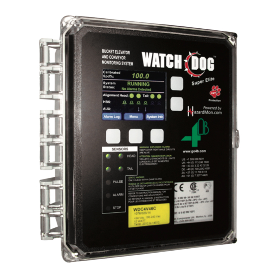
- Page 8 • Always lockout and tagout the machine prior to installation 2. PRODUCT OVERVIEW The Watchdog Super Elite (WDC4) is a user-programmable, microprocessor controlled bucket elevator and belt conveyor monitor. The control unit accepts signals from sensors for belt misalignment, belt speed &...
- Page 9 4. FEATURES BELT MISALIGNMENT DETECTION - The Watchdog Super Elite offers greater flexibility for belt misalignment monitoring. The supported methods are: METHOD DESCRIPTION APPLICATION Force activated contact signal. Standard method, most reliable for Contact When contact from the belt occurs misalignment detection.
- Page 10 HOT BEARING DETECTION - The Watchdog Super Elite can monitor up to 8 NTC type temperature sensors (standard). This can be expanded to a total of 20 NTC sensors with optional auxiliary boards. The supported alarm methods are: METHOD DESCRIPTION...
- Page 11 5. DIMENSIONS ALL DIMENSIONS IN INCHES 9-1/2 Ø 1-1/8 x 2 3-1/2 Ø 5/16 x 4 6. INSTALLATION The WDC4 should be installed in a suitable control or switch room, and mounted at eye level so that the warning lights and LED screen can be readily seen. ENCLOSURE INSTALLATION - 1.
- Page 12 7. SENSOR PLACEMENT DIAGRAMS TYPICAL SENSOR PLACEMENT FOR BUCKET ELEVATORS & ENCLOSED BELT CONVEYORS SPEED MONITORING Qty 1 - One sensor located on either side of the tail or boot shaft. BEARING TEMPERATURE Qty. 4 - One sensor for the bearings at each end of the drive and tail or head and boot shafts.
- Page 13 8. ELECTRICAL CONNECTION All wiring must be in accordance with local and national electrical codes and should be undertaken by an experienced and qualified electrician. Always use dust/liquid tight flexible metal conduit with approved fittings to protect the sensor cables. Use rigid metal conduit to protect the cables from the sensors to the control unit.
- Page 14 WARNING The unit should ONLY be powered with either a main supply (WDC4V46C model) OR a 24 VDC (WDC4V4C and WDC4V46C models) NOT BOTH (see specifications). FIELD WIRING CONNECTIONS 44 - 0 VDC 43 - Speed Sensor 42 - Pulley Sensor 41 - Plug Sensor 40 - Head Rub - Right 39 - Head Rub - Left...
- Page 15 9. WIRING DIAGRAMS 9.1 WIRING BLOCK DIAGRAM FOR BUCKET ELEVATOR & BELT CONVEYOR - Plug Switch (Optional) Hot Bearing Hot Bearing Sensor Sensor Junction Alignment Alignment HEAD / DRIVE Top Left Top Right Denotes shielded cable. Shield to WDC4 be grounded at Control Unit one end only.
- Page 16 9.2 CONTROL WIRING DIAGRAM FOR WDC4V46C (120 to 240 VAC) - Alarm and Stop Relays are Shown Energized in the Normal Running Condition 24 VDC Watchdog Watchdog Supply Alarm Relay Stop Relay 100 to 240 VAC 120 to 240 VAC No Connection Interlock Watchdog...
- Page 17 9.3 CONTROL WIRING DIAGRAM FOR WDC4V4C (24 VDC) - Alarm and Stop Relays are Shown Energized in the Normal Running Condition 24 VDC Watchdog Watchdog Supply Alarm Relay Stop Relay 24 VDC 120 to 240 VAC Interlock Supply (Run Signal) Not Connected The Unit Must be Grounded...
- Page 18 9.4 CONTROL WIRING DIAGRAM FOR MULTIPLE UNITS WIRED TO THE SAME ALARM - WATCHDOG CONTROL UNIT #1 Alarm and Stop Relays are Shown Energized in the Normal Running Condition 24 VDC Watchdog Watchdog Supply Alarm Relay Stop Relay 100 to 240 VAC 120 to 240 VAC Interlock Watchdog...
- Page 19 WATCHDOG CONTROL UNIT #2 Alarm and Stop Relays are Shown Energized in the Normal Running Condition 24 VDC Watchdog Watchdog Supply Alarm Relay Stop Relay 100 to 240 VAC 120 to 240 VAC Interlock Watchdog No Connection (Run Signal) Supply The Unit Must be Grounded Fuse...
- Page 20 Wiring diagrams for the four pre-programmed profiles are shown in sections 9.7 - 9.10. More wiring diagrams are available online, please refer to the WATCHDOG SUPER ELITE SENSOR WIRING DIAGRAMS manual that can be found at www.go4b.com/usa. This online manual will continue to be updated as new wiring diagrams are completed and added.
- Page 21 9.6 WDC3 (RETIRED MODEL) TO WDC4 SENSOR WIRING DIAGRAM MENU > SETUP (PASSWORD) > PROFILE > SELECT NEW PROFILE > LEG (WDA) 4MA, 4BS NOTE Wiring diagram 9.6 is for end users upgrading their WDC3 Watchdog to the WDC4 Watchdog Super Elite.
- Page 22 9.7 SENSOR WIRING DIAGRAM PROFILE WITH TOUCHSWITCHES - MENU > SETUP (PASSWORD) > PROFILE > SELECT NEW PROFILE > LEG (TS)/ 1SP, 4BS, 4TS Black Black 0 VDC Orange White Brown Speed Sensor Blue Pulley Sensor Green Alignment Plug Sensor Top (Head) Black Head Rub - Right (T#12)
- Page 23 9.8 SENSOR WIRING DIAGRAM PROFILE WITH RUB BLOCKS - MENU > SETUP (PASSWORD) > PROFILE > SELECT NEW PROFILE > LEG (RB)/ 1SP, 4BS, 4RB 0 VDC Speed Sensor Brown Black Brown Pulley Sensor Alignment Plug Sensor Top (Head) Head Rub - Right (T#12) Blue Black Head Rub - Left (T#11)
- Page 24 9.9 SENSOR WIRING DIAGRAM PROFILE WITH MOTION ALIGNMENT SENSORS - MENU > SETUP (PASSWORD) > PROFILE > SELECT NEW PROFILE > LEG (WDA) 4MA, 4BS 0 VDC Speed Sensor Orange Motion Green Alignment Black Pulley Sensor Black Sensor Brown Blue Plug Sensor White Alignment...
- Page 25 9.10 SENSOR WIRING DIAGRAM PROFILE WITH KNEE OR IDLER PULLEYS - MENU > SETUP (PASSWORD) > PROFILE > SELECT NEW PROFILE > LEG (TS)/ 1SP, 6BS, 6TS Black Black 0 VDC Orange White Brown Speed Sensor Blue Pulley Sensor Green Plug Sensor Black Head Rub - Right (T#12)
- Page 26 5 seconds (Image 3). The software version (Main IC) for the Watchdog will be listed during start- up, this will be required should you need to contact 4B for technical support. The WDC4 is normally supplied with its programmable parameters preset to factory default settings.
- Page 27 The last two icons on the far right of the auxiliary menu indicate motor interlock (run signal) and stop relay signals. These icons are used to assist with troubleshooting wiring problems. Normally the icons will both be the same color, if they are not contact 4B for assistance. • Motor Interlock (Run Signal) - When this icon is yellow and appears as a closed push button, it indicates that the Watchdog detects the motor interlock (run signal).
- Page 28 40) will be stored on the card. WARNING If the SD card is removed and more alarms occur, they will not be logged when the SD card is re- inserted. For uninterrupted historical data logging, 4B recommends using HazardMon.com. Date: Fri, Feb 26 2016...
- Page 29 NOTE To calibrate speed and utilize the Watchdog’s built-in alarm and shutdown capabilities, a motor interlock (run signal) is required. For typical motor interlock wiring examples, review the wiring diagrams for terminals 6 & 7. 2 of 9: Head Align Info Type: PULSED 2 of 9: Head Align Info...
- Page 30 AMB 1: 86.4 4 of 9: HBS Info AMB 2: 87.6 Sensor Value Abs. Rel. Trip HBS1 HBS2 HBS3 HBS4 HBS5 HBS6 Image 10 Previous Next Exit HBS Info Temperature Sensors 10.9 HBS INFO (4 OF 9) - The hot bearing sensor (HBS) screens show the actual temperature value (Value) of all the enabled bearing sensors and any selected absolute (Abs.) and relative (Rel.) alarm trip points.
- Page 31 7 of 9: AUX Sensor Info Plug Current State: Alarm State: Pulley Current State: Alarm State: Image 12 Previous Next Exit AUX Sensor Info 10.11 AUX SENSOR INFO (7 OF 9) - The Watchdog supports two auxiliary sensors, pulley alignment “Pulley” and plug condition “Plug”. The AUX Sensor Info screen (Image 12) shows the current and alarm states for these sensors.
- Page 32 HazardMon.com network settings can be found in the Network Settings Menu (Section 20). For more information about HazardMon.com, contact 4B or visit us on the web at www.go4b.com/usa. 11. VIEW SETTINGS View Settings Setup Reset Eng.
- Page 33 B and C. If you change the password from the factory default, make a note of your new password. NOTE If the engineering password has been changed from the factory default and you have forgotten your new password, contact 4B for assistance. Profile Test...
- Page 34 If the engineering password has been changed from the factory default and you have forgotten your new password, it can be reset. In order to perform a password reset, you will need to contact 4B technical support and supply them with the four digit code displayed on the RESET ENG. PASSWORD screen (Image 19).
- Page 35 14. PROFILE 14. PROFILE - MENU > SETUP (PASSWORD) > PROFILE The first choice under the SETUP menu is PROFILE (Image 17), which allows you to edit individual section settings without having to go through the entire FULL SYSTEM SETUP. Once PROFILE has been selected, you will see the next sub-menu (Image 20) where you can EDIT SELECTED PROFILE, RESTORE DEFAULTS or SELECT NEW PROFILE.
- Page 36 NOTE When the Watchdog is powered up it reads the stored setup parameters from its memory. These will be used during operation. New Watchdogs are set to the factory default values (Appendix B). 14.2 CALIBRATE SYSTEM - MENU > SETUP (PASSWORD) > PROFILE > EDIT SELECTED PROFILE > CALIBRATE SYSTEM The Watchdog must be calibrated to correctly monitor the speed of an elevator or conveyor belt.
- Page 37 Calibrate System Full System Setup System Speed Alignment Temperature Auxiliary Expansion Boards Image 23 Edit Selected Profile - Back Full System Setup 14.3 FULL SYSTEM SETUP - MENU > SETUP (PASSWORD) > PROFILE > EDIT SELECTED PROFILE > FULL SYSTEM SETUP Watchdog control units are preset with factory default values (Appendix B).
- Page 38 1. MAS SPEED INPUT - This option is selected when using multiple speed sensors, such as 4B’s WDA Motion Alignment Sensor (MAS). MAS sensors can be used to detect the passage of buckets when the elevator belt is in motion. As each bucket passes a sensor, a pulse is generated and the Watchdog uses these pulses to measure belt speed and alignment between the sensors.
- Page 39 3. DIFFERENTIAL SPEED - Differential speed monitoring is selected when you intend to monitor an elevator or conveyor belt that may intentionally vary in speed as part of the process or when that belt is driven by a variable speed controller. The monitoring of differential speeds usually takes place between the top of the elevator (the drive end) and the bottom (the driven end).
- Page 40 Below are examples of how the Watchdog sees the two speeds: • Example 1: Speed 1 - 426 PPM Speed 2 - 987 PPM Ratio of speed 2 to speed 1 = 2.316 (987/426) If the elevator was to increase in speed so that speed 1 was now 556 PPM then speed 2 should be speed (556 X 2.316) or 1288 PPM (these figures are rounded).
- Page 41 • 14.5.F NUMBER OF STARTS / MINUTE - This function is used to prevent damage to the motor and the motor start circuitry by limiting the number of times in a minute the system can be started. This setting can range from 1 to 10, the default is 3. When the Watchdog is started and a shutdown fault occurs, a jog delay is introduced.
- Page 42 After the alarm delay time has elapsed and the alarm has been triggered, the stop delay timer will be displayed on the main LCD. If the Watchdog reaches the UNDERSPEED STOP DELAY time, the stop relay is de-energized, the STOP LED on the Watchdog lights up red, and a warning showing the source of the stop condition is displayed in red on the main LCD screen.
- Page 43 3. Contact (Default Setting) 4. Rub Block PULSED - Choose this option if using 4B WDA Motion Alignment Sensors, or Touchswiches that are receiving pulses from a P800. The number of pulses detected by the sensors on the right and left sides are compared.
- Page 44 • 14.6.D RELATIVE ALARM SOURCE - If RUB BLOCK is selected within the HEAD SENSOR PAIR menu, a relative alarm source must be selected. Choices are OFF, AMB1, AMB2 or OPPOSITE, the default is OFF. If either AMB1 or AMB2 are selected, the relative alarm temperature is relative to the ambient temperature.
- Page 45 • 14.6.G HEAD ALARM DELAY [S] - The delay in seconds before the system alarms after a sensor trips. The delay can be set from 0 to 10 seconds, the default is 1. Configuring the delay above zero can help prevent nuisance alarms. When a sensors trips, a cumulative alarm delay counter starts to count down.
- Page 46 3. Contact (Default Setting) 4. Rub Block PULSED - Choose this option if using either 4B’s WDA Motion Alignment Sensors or Touchswiches that are receiving pulses from a P800. The number of pulses detected by the sensors from the right and left sides are compared, if the difference between the two exceeds 66% an alarm condition is generated.
- Page 47 • 14.7.F TAIL: RATE OF RISE [DEG/MIN] - If RUB BLOCK is selected within the TAIL SENSOR PAIR menu and RELATIVE ALARM SOURCE is set to AMB1, AMB2 or OPPOSITE, you can choose to turn the rate of rise ON (default) or OFF. If RELATIVE ALARM SOURCE is set to OFF, you will not be able to choose RATE OF RISE.
- Page 48 Calibrate System Full System Setup System Speed Alignment Temperature Auxiliary Expansion Boards Image 29 Edit Selected Profile - Back Temperature 14.8 TEMPERATURE - MENU > SETUP (PASSWORD) > PROFILE > EDIT SELECTED PROFILE > TEMPERATURE The Watchdog can monitor up to 8 NTC type temperature sensors (standard) or up to 20 with additional NTC expansion boards.
- Page 49 • 14.8.D HBS1: RELATIVE ALARM [DEG] - If AMB1 OR AMB2 is selected within the RELATIVE ALARM SOURCE menu, a relative temperature value must be selected. If the measured temperature of the bearing sensor exceeds the relative temperature value, an alarm is generated.
- Page 50 • 14.8.J AMB1: RATE OF RISE [DEG/MIN] - You can choose to turn the rate of rise ON or OFF (default). If turned OFF, the rate of rise is ignored and no alarm will be generated. If turned ON, this setting monitors the rate of rise of the ambient sensor temperatures. It is designed to detect when temperature rises are in excess of what might be considered normal.
- Page 51 • 14.9.A PLUG ENABLED - Choices are ON or OFF (default). A plug or choke sensor is usually used for blocked chute detection. A Binswitch Elite is most commonly used however, an Auto-Set™ flush probe can also be installed depending on the application. When a plug sensor is installed and PLUG ENABLED is ON, the Watchdog looks for a change in signal level representing the plug condition.
- Page 52 For installation instructions and board specifications, refer to the specific expansion board manual. WARNING Expansion boards are NOT suitable for HOT INSTALL. Expansion boards should NOT be installed while the WDC4 is powered. Refer to the board’s manual for installation information or contact 4B. PAGE 52...
- Page 53 Since the menus are the same for both expansion boards, expansion board 1 (EXP 1) will be used as a template for this manual. • 14.10.A EXPANSION 1 & 2 - After installing the expansion board(s) into the WDC4, note the location (1 or 2) as outlined in the board’s installation manual.
- Page 54 • 14.10.C PLC BOARD - The PLC board (WDC4-AUXO-4SSR) provides the ability to connect additional signals from the WDC4 to a PLC. The board has 4 solid state relays (50 mA max.) that can be used to indicate alarm conditions related to speed, alignment, temperature and auxiliary alarms as four separate signals.
- Page 55 – 14.10.D.13 CLI1: ALARM DELAY [S] - The delay in seconds before the system alarms after a sensor trips (absolute alarm high / low value). The delay can be set from 0 to 10 seconds, the default is 1. Configuring the delay above zero can help prevent nuisance alarms. When a sensors trips, a cumulative alarm delay counter starts to count down.
- Page 56 The example CLI1 settings below are based on 4B’s Milli-Speed switch. The Milli-Speed has a 4-20 mA output designed to detect belt slip, belt underspeed, stop motion, low speed or zero speed. Referring to the manual for the Milli-Speed, at calibrated speed the output will be set to 17 mA (100%).
- Page 57 • 14.10.E ANALOG BOARD (2AN) - The analog board (WDC4-AUXI-2AN) provides the ability to connect 2 current loop inputs (CLI1 - CLI2) for 0 to 20 mA sensors to measure current. Settings for the CLI inputs are similar to the ANALOG BOARD (6AN), refer to 14.10.D for setup details. •...
- Page 58 Over Write Existing Settings? Image 35 Profile - Restore Defaults 14.11 RESTORE DEFAULTS - MENU > SETUP (PASSWORD) > PROFILE > RESTORE DEFAULTS (PASSWORD) All settings in the Watchdog can be restored to the factory default settings as described in Appendix B. Before allowing the settings to be reset, the user is prompted to enter the engineering password again and a final confirmation screen to confirm the action is displayed (Image 35).
- Page 59 15. TEST Profile Test Factory Settings SD Card Time & Date Change Password Network Image 37 Back Setup Menu - Test 15. TEST - MENU > SETUP (PASSWORD) > TEST A number of test functions are available to simulate various fault conditions to validate the functionality of the alarm and stop relays (Image 37).
- Page 60 When this menu is selected, the screen will display a 4 digit number generated by the Watchdog (Image 39). You must give this code to a 4B technical support representative, and after they verify that the changes you intend to make will leave the Watchdog in a safe working condition will in return give you a 4 digit administrator password.
- Page 61 The EDIT SELECTED PROFILE menu within FACTORY SETTINGS is almost an exact duplicate of the menus found under PROFILE. FACTORY SETTINGS allow for a wider range of system adjustments which should only be changed by advanced users. 4B recommends using the standard settings found within the PROFILE menu. Refer to PROFILE for more details.
- Page 62 17. SD CARD Profile Test Factory Settings SD Card Time & Date Change Password Network Image 41 Back Setup Menu - SD Card 17. SD CARD - MENU > SETUP (PASSWORD) > SD CARD All of the settings in the Watchdog can be saved to and loaded from an SD card inserted into the System Card / SD Card 1 slot (Image 40) inside the control unit.
- Page 63 A, B and C. If you change the password from the factory default, make a note of your new password because if you lose it you will not be able to make changes to the Watchdog. If you do lose the password, contact 4B technical support. PAGE 63...
- Page 64 20. NETWORK - MENU > SETUP (PASSWORD) > NETWORK • HazardMon - The Watchdog Super Elite can be integrated into HazardMon.com ®, which is a secure cloud based hazard monitoring solution providing status notifications and data logging for bucket elevators and conveyors. Live system status, graphs and historical data can be viewed on any web- enabled device (smartphone, tablet PC, desktop or laptop computer).
- Page 65 21. TROUBLESHOOTING GUIDE For details on specific alarms, go to the ALARM LOG and choose MORE INFO. This will provide you with details on the alarm such as: date, time, entry type, entry source, condition and data that is alarm dependent by type.
- Page 66 LCD Icon LCD Status FAULT CAUSE / REMEDY Watchdog sending stop Wiring fault with stop relay or interlock signal out, however run (run signal). Equipment monitored Messages Can Vary signal is still applied (refer and interlock (run signal) needs to to section 10.2) turn off when stop relay opens.
- Page 67 22. APPENDIX A - WDC4 MENU TREE Watchdog Main Screen Alarm Log Menu System Info Speed Info View Settings Setup Reset Eng. Password Head Align Info (No Password) (Eng. Password) Tail Align Info HBS Info EXP1 Info System Settings EXP2 Info Speed Settings AUX Sensor Info Alignment Settings...
- Page 68 23. APPENDIX B - FACTORY DEFAULT SETTINGS Some settings are dependent on others, so not all may be displayed or available to select. SYSTEM DEFAULT OPTIONS • Temperature Units °F °F / °C • Negative Differential Alarm On / Off •...
- Page 69 Some settings are dependent on others, so not all may be displayed or available to select. TEMPERATURE DEFAULT OPTIONS • HBS1 - HBS4 (Sensors 1 - 4) On / Off • HBS5 - HBS6 (Sensors 5 - 6) On / Off •...
- Page 70 24. APPENDIX C - WDC4 CONFIGURATOR SOFTWARE The Watchdog Super Elite can be programed directly through the controller’s LCD menu screen, or by using the WDC4 Configurator Software. The software tool makes programming the Watchdog easier by providing all the system settings for each profile menu into one screen (Image 45).
- Page 71 7. After the update has successfully loaded, remove the SD card. 8. Secure the lid of the unit by re-tightening the screws. If the new software did not install, repeat the software update process. If the upload continues to fail, contact 4B. WDC4 - Super Elite www.go4b.com Initializing...
- Page 72 END USER NOTES PAGE 72...
- Page 73 END USER NOTES PAGE 73...
- Page 74 END USER NOTES PAGE 74 PAGE 74...
- Page 75 AS 4B TO THE ORIGINAL PURCHASER AGAINST DEFECTS IN WORKMANSHIP OR MATERIALS UNDER NORMAL USE FOR ONE (1) YEAR AFTER DATE OF PURCHASE FROM 4B. ANY PRODUCT DETERMINED BY 4B AT ITS SOLE DISCRETION TO BE DEFECTIVE IN MATERIAL OR WORKMANSHIP AND RETURNED TO A 4B BRANCH...
- Page 76 Tel: +61 (0) 7 3216 9365 Fax: 309-698-5615 Fax: +33 (0) 3 22 42 37 33 Tel: +27 (0) 11 708 6114 Fax: +61 (0) 7 3219 5837 Fax: +27 (0) 11 708 1654 www.go4b.com Copyright © 2018 4B Group - All Rights Reserved REV110818...
Need help?
Do you have a question about the Watchdog Super Elite and is the answer not in the manual?
Questions and answers