
Related Manuals for 4B M100


Summary of Contents for 4B M100
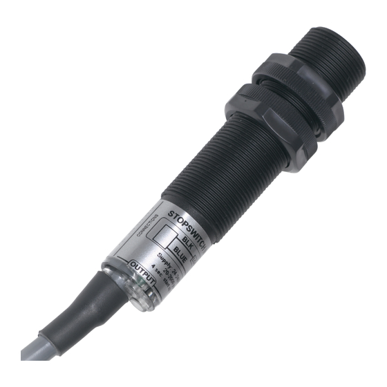
- Page 1 M100 Stopswitch STOPPED MOTION MONITOR INSTALLATION INSTRUCTIONS OPERATION MANUAL Part No.’s - M1003V10AI www.go4b.com...
-
Page 2: Table Of Contents
TABLE OF CONTENTS CUSTOMER SAFETY RESPONSIBILITIES Page 3 - 4 PRODUCT OVERVIEW Page 5 SPECIFICATIONS Page 5 APPROVALS Page 6 DIMENSIONS Page 7 INSTALLATION Page 7 - 8 STANDARD WIRING DIAGRAM Page 8 - 9 TESTING & COMMISSIONING Page 9 - 10 TROUBLESHOOTING GUIDE Page 10 PRODUCT WARRANTY... -
Page 3: Customer Safety Responsibilities
The proper installation and maintenance of all our products is the responsibility of the user unless you have asked 4B to perform these tasks. B. All installation and wiring must be in accordance with Local and National Electrical Codes and other standards applicable to your industry. - Page 4 3. SELECT A QUALIFIED AND COMPETENT INSTALLER Correct installation of the product is important for safety and performance. If you have not asked 4B to perform the installation of the unit on your behalf, it is critical for the safety of your operation and those who may perform work on your operation that you select a qualified and competent electrical installer to undertake the installation.
-
Page 5: Product Overview
An inductive sensing device located in the nose of the M100 enclosure will detect a metal target. Ideally, the target should be a ferrous metal, but non-ferrous metal will be detected at a shorter range. Maximum range for ferrous targets is 6 mm (15/64 in.) and for non-ferrous targets it is 5 mm (13/64 in.), assuming... -
Page 6: Approvals
APPROVALS Baseefa14ATEX0115X <Ex> II 2G Ex mb IIC T5 Gb ATEX <Ex> II 2D Ex mb IIIC t100 C Db Tamb - 15 C to +50 C <Ex> I M2 Ex mb I Mb IECExBAS14.0061X Ex mb IIC T5 Gb Ex mb IIIC t100 C Db IECEx I M2 Ex mb I Mb... -
Page 7: Dimensions
It is not recommended to wire the M100 Stopswitch in series with other sensors. The cable on the M100 Stopswitch can be extended to virtually any length in ordinary 2 wire cable. Two locknuts are provided to mount the M100 Stopswitch in position. Mount securely to withstand vibration. -
Page 8: Standard Wiring Diagram
The M100 has a two wire cable. It must be wired through a load (see below) with the same voltage rating as the supply being used. The supply polarity to the M100 is not important and the load can be connected to either wire. -
Page 9: Testing & Commissioning
3. Start up machine. 4. The unit is now set. If the M100 Stopswitch fails to receive a signal within every 4 second period, (i.e. target stops rotating or there is a power failure) the unit will switch to normally open. -
Page 10: Troubleshooting Guide
50mA. Slide a screwdriver blade across the face Blue LED (input) does of the sensor, the input LED should flicker. If not, contact 4B. not Illuminate If the input LED does flicker, move the front face of the sensor closer to the target and check the target size as specified under “INSTALLATION”. -
Page 11: Product Warranty
The proper installation and maintenance of all our products is the responsibility of the user unless you have asked 4B to perform these tasks. B. All installation and wiring must be in accordance with Local and National Electrical Codes and other standards applicable to your industry. - Page 12 Fax: +33 (0) 3 22 42 37 33 Tel: +27 (0) 11 708 6114 Tel: +61 (0)7 3216 9365 Fax: +27 (0) 11 708 1654 Fax: +61 (0)7 3219 5837 www.go4b.com Copyright © 2018 4B Group - All Rights Reserved REV072518...
Need help?
Do you have a question about the M100 and is the answer not in the manual?
Questions and answers